
Key Takeaways
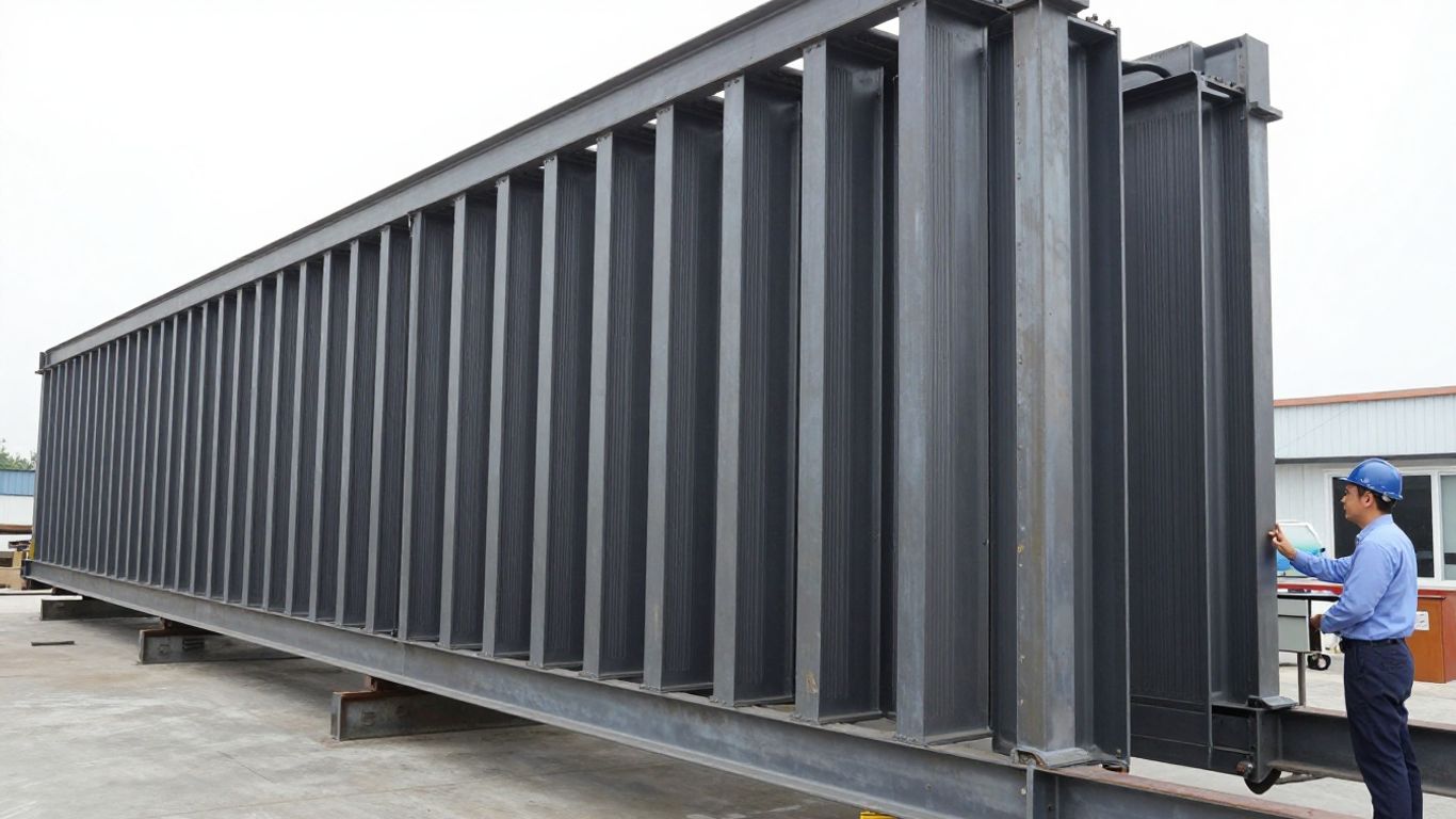
Deep steel girders are especially sensitive to plate instability because slender webs can buckle before the overall member reaches its full strength. A credible analysis therefore depends on the physical model, the FEA Mesh, nonlinear assumptions, and a disciplined convergence study.
- Web slenderness, aspect ratio, stiffeners, and load introduction all influence buckling behavior.
- Shell elements are often efficient for thin plates, provided their connections and boundary conditions are represented carefully.
- Mesh refinement should follow stress gradients, deformation patterns, supports, and concentrated loads.
- Eigenvalue analysis identifies likely modes, while nonlinear analysis provides a more realistic capacity assessment.
- FEA results should support, not replace, engineering judgment and applicable code checks.
Understand plate buckling in deep steel girders
Plate buckling in a deep girder is a stability problem rather than simply a strength problem. The web may lose stiffness under shear or compression while the flanges continue to carry load, creating a response that is strongly dependent on geometry and restraint. A useful model must distinguish the first visible instability from the load the complete girder can ultimately sustain.
Why deep webs are vulnerable to instability
A deep web carries substantial shear and normal stress across a relatively large, thin panel. As its depth-to-thickness ratio increases, the elastic critical stress can fall below the material yield stress, especially where the panel is poorly restrained. Small geometric deviations, uneven loading, and residual stress can then steer the web toward an out-of-plane deformation pattern.
The practical consequence is that increasing girder depth does not automatically produce a proportional increase in capacity. A deeper web can improve bending efficiency while also creating larger unsupported panels. The analysis should therefore examine both the intended load path and the stability of each web panel between transverse or longitudinal restraints.
Local, distortional, and global buckling modes
Local buckling is confined mainly to the web or flange plate. Distortional buckling involves movement of a plate together with its stiffener or adjacent flange, while global buckling affects the girder as a member through lateral, torsional, or flexural deformation. These modes may interact rather than appear as neatly separated events.
Eigenvalue results are useful for identifying likely shapes, but the lowest eigenvalue is not automatically the governing design condition. A mode with a slightly higher factor may couple more strongly with the applied loading or with realistic imperfections. Reviewing several mode shapes, their locations, and their compatibility with the load path is more informative than reading one number in isolation.
The effects of web slenderness and aspect ratio
Web slenderness is commonly expressed through depth and thickness, but the panel aspect ratio also matters. A short panel bounded by stiffeners behaves differently from a long panel with the same thickness, because the available buckling half-waves and edge restraint change. Boundary conditions at the flanges and transverse stiffeners can raise or lower the effective stability of the panel.
A parametric study can separate these effects. Varying web thickness, stiffener spacing, or panel length one at a time helps reveal whether the design is controlled by shear buckling, compression buckling, or a coupled response. It also provides a better basis for deciding where a finer mesh is worth the added cost.
How stiffeners, flanges, and load introduction influence buckling
Stiffeners do more than divide a web into smaller rectangles. Their axial and bending stiffness, attachment detail, and termination affect how forces move between plates. Flanges provide edge restraint, but that restraint is not necessarily rigid, particularly near a support, splice, bearing, or concentrated force.
Load introduction deserves equal attention. A bearing reaction or patch load can create a steep stress gradient and a local web deformation that is not visible in a simplified beam model. The analyst should inspect the surrounding flange, web, and stiffener behavior together rather than treating the load as an ideal point with no physical footprint.
Build an analysis-ready girder model
An analysis-ready model begins with a clear structural idealization. Before generating elements, define what the model is intended to answer, which load path must be preserved, and which details can safely be simplified. Aman Engineering Consultancy approaches structural work with attention to international standards and design endorsement requirements, so the assumptions behind a finite element model should remain traceable to the governing design basis.
Defining geometry, supports, and load paths
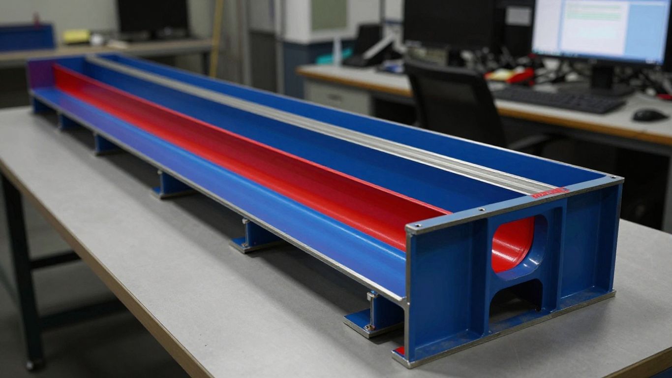
Model the web, flanges, stiffeners, diaphragms, bearings, and load patches at a level that matches the question being asked. Centerline geometry may be adequate for a global response, but plate buckling requires realistic plate dimensions, offsets, thicknesses, and intersections. Supports should restrain the intended degrees of freedom without accidentally adding a diaphragm that the physical girder does not possess.
Load paths should be checked visually and through reactions. Apply distributed loads or contact areas where the real structure transfers force over a finite region. If a concentrated load is unavoidable, evaluate whether the resulting singularity is a modeling artifact or a meaningful local demand.
Selecting shell, solid, or beam elements
Shell elements are usually an efficient choice for thin webs and flanges because they capture membrane and bending behavior without filling the entire plate thickness with solid elements. Solid elements become more useful around thick bearing details, complex weld geometry, or through-thickness stress questions. Beam elements can represent global members and stiffeners, but they cannot by themselves reproduce a web plate’s out-of-plane buckling pattern.
The choice should follow the failure mechanism, not software convenience. A mixed model can be appropriate when a detailed local region is connected to a larger girder, provided that displacement compatibility, offsets, and force transfer are checked carefully. For background on how elements and nodes discretize structural geometry, see this FEA meshing guide.
Representing web stiffeners and flange-to-web connections
Stiffeners should be modeled with their actual spacing and a suitable representation of their section stiffness. A shell stiffener may be attached through shared nodes, an offset connection, or a compatible coupling formulation, depending on the solver and the physical detail. Whichever approach is used, confirm that it does not create an unintended hinge or an artificially rigid seam.
The flange-to-web junction also needs a deliberate treatment. Shared midsurfaces can be efficient, but eccentricity and weld flexibility may matter near local buckling or patch loading. If the connection is simplified, record which local effects are excluded and avoid interpreting the result as a detailed weld assessment.
Including material properties and boundary conditions
For an elastic eigenvalue study, define the elastic modulus, Poisson’s ratio, density where relevant, and the intended stress state. Nonlinear analysis additionally requires a suitable stress-strain relationship, yield strength, hardening assumptions, and any residual stress pattern considered representative. Material data should be consistent with the selected design standard and project specification.
Boundary conditions deserve a separate review because they often govern the first mode. Restraints at bearings, symmetry planes, diaphragms, and adjacent members should reflect actual movement and rotation. Over-constraining a flange or web can suppress a physically plausible mode while under-constraining the model can produce rigid-body motion or a meaningless mechanism.
Avoiding idealizations that suppress realistic buckling behavior
Common shortcuts include making every stiffener infinitely rigid, tying all intersecting plates without offsets, fixing broad regions that should move, and replacing a load patch with a single node. These assumptions may stabilize the model numerically while removing the deformation pattern being investigated. A useful check is to compare the idealized model’s reaction distribution and mode shapes with a less constrained trial model.
A model should be simple enough to audit but detailed enough to let the expected instability develop. Physical fidelity matters most in the zones where restraint, load transfer, and plate deformation interact; adding cosmetic geometry elsewhere rarely improves the answer.
Establish a practical FEA mesh strategy
Mesh planning should begin after the structural behavior has been identified, not before. The aim is to resolve the relevant deformation wavelengths and stress gradients while keeping the model economical. The broader principles described in this FEA meshing reference apply directly here: the mesh is a numerical representation of geometry and behavior, not a substitute for understanding either one.
Choosing element types and starting mesh sizes
Use predominantly quadrilateral shell elements for regular web and flange panels where the formulation is suitable, adding triangles only where geometry requires them. Begin with a regular, moderate mesh that can reveal global deformation and likely buckling zones. The initial size should relate to web thickness, stiffener spacing, load footprint, and the expected half-wave length rather than an arbitrary universal value.
A coarse starting model is valuable because it exposes connectivity and boundary-condition errors quickly. It also gives a baseline against which local refinement can be judged. Mesh size should then be reduced in controlled stages, with the same loads, constraints, material data, and solver settings retained between runs.
Aligning the mesh with plate boundaries and stiffeners
Mesh lines should follow web edges, flange toes, stiffener centerlines, bearing limits, and other meaningful geometric boundaries whenever possible. Alignment makes panel dimensions explicit and avoids distorted elements at the places where a buckling wave is expected to form. It also simplifies the comparison of corresponding nodes and response locations across mesh versions.
Where a stiffener intersects a web, compatible divisions help transfer forces cleanly. If the mesh cannot be made conforming, use a connection method that has been verified for the intended shell formulation. A visually dense mesh with poor connectivity is less useful than a slightly coarser mesh that preserves the structural topology.
Refining regions around supports and concentrated loads
Supports and concentrated loads generate local gradients that can dominate stress results. Refine around bearing plates, load patches, web gaps, stiffener ends, cut-outs, and abrupt changes in restraint. Extend the refined zone far enough that the transition occurs outside the area used for the key response measurement.
Do not refine only the single node where a load is applied. Instead, model the physical contact or distribute the force across an appropriate area, then refine the surrounding plates. This approach reduces artificial peaks and makes the observed deformation easier to interpret.
Maintaining element quality and compatible transitions
Check aspect ratio, warping, skewness, Jacobian quality, and abrupt size changes. Very elongated elements can miss a buckling wave in one direction even when the element count looks high. Sudden transitions can also reflect waves or concentrate strain for numerical reasons rather than physical ones.
A compatible transition from fine to coarse elements should preserve the dominant deformation pattern. Review both the mesh-quality report and a deformed-shape plot, since acceptable geometric metrics do not guarantee that the mesh is adequate for the mode of interest.
Balancing model detail with computational efficiency
The most efficient model is not necessarily the one with the fewest elements. It is the one that spends degrees of freedom where they affect the decision and avoids detail that cannot change the decision. A global model can identify load distribution and boundary behavior, followed by a refined submodel for a critical web panel if the interface forces and displacements are transferred consistently.
Keep a repeatable naming convention for mesh versions and record element counts, refined regions, solver settings, and response quantities. That simple discipline makes later review much easier, especially when several design alternatives are being compared.
Refine the mesh for plate buckling accuracy
Refinement is most effective when guided by results from the previous run. Examine contours of out-of-plane displacement, principal stress, shear stress, and reaction transfer rather than refining the entire girder uniformly. The purpose is to resolve the physical pattern of instability and obtain stable engineering quantities, not merely to produce a visually dense model.
Identifying high-gradient stress and deformation zones
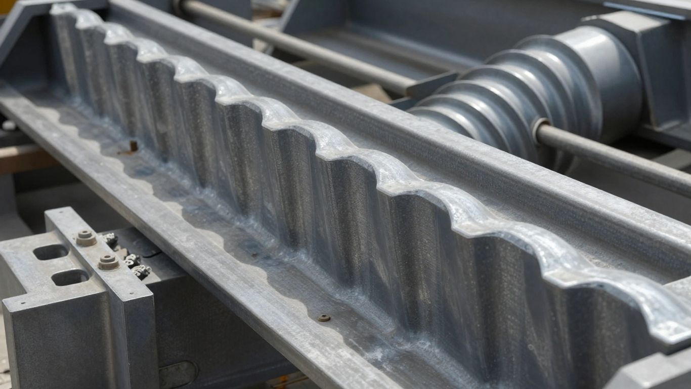
High gradients commonly occur near supports, patch loads, stiffener terminations, web openings, flange transitions, and load-introduction points. They may also appear along the crest and trough of a developing buckling wave. Use these regions to place additional divisions, then inspect whether the gradient becomes more physically coherent as the mesh is refined.
Stress singularities at sharp corners or idealized point loads should not be treated as ordinary convergence targets. Use averaged or section-based quantities where appropriate, and explain the chosen extraction method. Displacement patterns and integrated forces are often more reliable indicators of structural behavior than a single extreme element stress.
Capturing web buckling half-waves with sufficient elements
A mesh must contain enough elements across each anticipated half-wave to describe its curvature. If only one or two elements span a wave, the mode shape may be forced into an artificial pattern, and the eigenvalue can shift substantially with small changes in mesh alignment. Begin with the expected panel dimensions and mode shape, then confirm adequacy by comparing successive refinements.
The required density is formulation-dependent and should be demonstrated rather than assumed. Mode shapes should become smoother and more stable as the mesh is refined. If the critical mode changes repeatedly, investigate boundary conditions, mode interactions, and element formulation before simply adding more elements.
Modeling stiffener spacing and local connection behavior
Stiffener spacing defines the web panels that may buckle, while the stiffener’s own flexibility influences the restraint available at each panel edge. Refine along both sides of a stiffener when local bending or separation is relevant. At a termination, include enough resolution to capture the transfer from the stiffened region into the unstiffened web.
The connection representation should be consistent across mesh levels. Changing from shared nodes to a rigid constraint at the same time as refining the mesh makes the comparison ambiguous. Mesh studies are meaningful only when the physical idealization remains otherwise unchanged.
Comparing coarse, medium, and fine mesh results
A mesh convergence study should compare like with like. The following table provides a practical set of quantities and what each one can reveal during refinement.
| Response quantity | Why it matters | Typical interpretation |
|---|---|---|
| First relevant eigenvalue | Indicates elastic instability sensitivity | Strong mesh change suggests unresolved mode or boundary issue |
| Peak out-of-plane displacement | Tracks the buckling shape | Stabilization supports adequate wave resolution |
| Section reaction or resultant | Checks load transfer | Variation may indicate poor support or contact modeling |
| Averaged web stress | Supports design interpretation | More useful than an isolated singular element value |
After each run, compare the location as well as the magnitude of the response. A stable value at the wrong location is not evidence of a reliable model. The table should guide the review, while engineering judgment determines which quantity governs the design question.
Recognizing when additional refinement no longer changes the result
Refinement can be considered sufficient when the selected engineering responses change only within a predefined tolerance across the final mesh levels and the relevant mode shape remains consistent. The tolerance should be chosen before reviewing the final result, with tighter control for safety-critical decisions or highly localized behavior.
Do not confuse numerical smoothness with physical certainty. A result may converge for an over-constrained model, an unrealistic imperfection, or an incorrect load path. Mesh independence is one part of verification; model sensitivity and code comparison remain necessary.
Combine eigenvalue and nonlinear buckling analysis
Eigenvalue analysis and nonlinear analysis answer different questions. The first estimates elastic critical factors and reveals possible instability shapes; the second follows a response that can include imperfections, yielding, changing stiffness, and post-buckling behavior. Used together, they provide a more useful picture than either method alone.
Using eigenvalue analysis to identify critical modes
Run an eigenvalue analysis after confirming that the model has no unintended mechanisms and that the load pattern reflects the intended combination. Review several modes, including their locations, symmetry, and relationship to stiffeners and supports. The mode selected for nonlinear initialization should be physically plausible, not simply the mathematically lowest one.
Multiple modes may be combined when manufacturing or erection imperfections are expected to contain more than one characteristic shape. The chosen approach should be stated clearly because it can influence the predicted nonlinear path.
Introducing geometric imperfections into the model
A perfect shell can remain artificially stable until a bifurcation point, whereas a real girder contains out-of-flatness from fabrication, handling, and erection. Imperfections can be introduced using scaled eigenmodes or measured and code-based shapes. Their amplitude, sign, combination, and location should be documented.
Sensitivity runs with plausible imperfection patterns are often more informative than one highly precise but weakly justified pattern. If the predicted capacity changes sharply, the result should be reported as imperfection-sensitive rather than presented as a single exact value.
Accounting for material yielding and residual stresses
Nonlinear material behavior allows the model to distinguish elastic instability from yielding and redistribution. Define the yield surface and hardening behavior consistently with the steel specification. Residual stresses from welding or fabrication may reduce buckling resistance and should be included when they are significant to the assessment and can be represented credibly.
Residual stress assumptions should not be added merely to make the result conservative without explanation. State their source, idealization, and orientation. Their interaction with geometric imperfections can be especially influential in slender web panels.
Applying nonlinear solution controls and convergence checks
Use displacement control, arc-length methods, or other suitable controls when load control cannot pass a limit point. Monitor iteration counts, residual norms, stiffness changes, and equilibrium errors. A solver warning or abrupt loss of convergence is not automatically the physical ultimate load.
Check whether the response is sensitive to increment size, stabilization, contact settings, and convergence tolerances. A repeatable equilibrium path with a clear deformation mechanism is more persuasive than a single run that happens to reach a higher load.
Interpreting elastic critical loads versus ultimate capacity
The elastic critical load marks the onset of a mathematical instability in the idealized elastic model. Ultimate capacity may be higher or lower depending on post-buckling reserve, yielding, imperfections, residual stresses, and interaction with other modes. These values should never be reported as interchangeable.
For design, identify which limit state is being checked and how the analytical or code method defines resistance. FEA can clarify the mechanism and support a refined assessment, but it does not remove the need for suitable resistance factors and professional review.
Verify mesh independence and model reliability
Verification asks whether the numerical model has been solved and discretized adequately; validation asks whether the model represents the physical girder well enough for its intended use. Both matter in plate buckling because a plausible contour can emerge from a flawed model. A short, pre-agreed verification plan is usually more valuable than an elaborate study assembled after the result is known.
Selecting response quantities for convergence studies
Select quantities that correspond to the design decision. For a web buckling assessment, that may include the relevant eigenvalue, a panel displacement, an averaged shear stress, a reaction resultant, and the load at a defined nonlinear event. Avoid relying only on peak nodal stress, particularly at idealized corners or point loads.
The extraction locations and averaging rules should remain fixed across mesh levels. If the response point moves because the mode shifts, record that shift rather than quietly changing the measurement location.
Tracking buckling load, displacement, stress, and reaction changes
Create a consistent comparison sheet for coarse, medium, and fine models. Record element count, smallest element size, eigenvalue or nonlinear buckling load, maximum meaningful displacement, representative stress, and support reactions. Reviewing trends is more useful than focusing on the finest model in isolation.
A converging load with non-converging local stress may be acceptable for a global capacity decision but not for a connection or fatigue assessment. Conversely, a stable stress average with a shifting deformation mode may signal that the mesh is not resolving the governing instability.
Distinguishing numerical instability from physical buckling
Physical buckling usually has a coherent deformation pattern, a compatible load redistribution, and a discernible change in tangent stiffness or equilibrium path. Numerical instability may instead appear as isolated element distortion, unexplained reaction imbalance, rigid-body movement, or sensitivity to solver settings without a corresponding structural mechanism.
Plot the deformed shape at several increments and inspect energy balance where available. Compare the behavior with hand calculations, code expectations, or a simplified model. These checks help determine whether a dramatic contour is meaningful or merely a numerical symptom.
Checking sensitivity to imperfections and boundary conditions
Run controlled variations in imperfection amplitude and shape, bearing restraint, flange continuity, and stiffener attachment where those assumptions are uncertain. The objective is not to find a single favorable answer, but to establish the range of plausible behavior and identify the assumptions that control it.
If small changes produce large capacity differences, the design may require better fabrication information, physical testing, a more detailed local model, or a conservative code-based treatment. Sensitivity is itself a finding that belongs in the engineering record.
Documenting mesh refinement decisions for design review
A review package should show the model purpose, geometry idealizations, element formulation, mesh levels, quality checks, boundary conditions, loading, material assumptions, imperfection treatment, and convergence criteria. Include mode shapes and deformed plots at consistent scales, not just colorful contour images.
Aman Engineering Consultancy’s professional engineering work spans Singapore and international requirements, including standards such as SS, BS, ACI, and Eurocode. That context makes clear documentation especially important when an FEA result is used to support authority submission, independent checking, or back-to-back engineering endorsement.
Apply results to design decisions and code checks
FEA is most useful when it answers a defined design question. For a deep girder, that may involve web shear buckling, patch loading, stiffener adequacy, or the efficiency of an alternative proportion. The output should be translated into forces, resistances, limit states, and detailing decisions that can be checked independently.
Evaluating web shear buckling and patch loading resistance
Use the model to identify the web panel that governs and to understand how shear, compression, bearing, and flange restraint interact. For patch loading, examine the load footprint, local web crippling or yielding, and the spread of force into the flanges and stiffeners. The mesh should be demonstrably adequate in that local region before the result is used.
Compare the calculated behavior with the relevant analytical expression or code procedure. If the model predicts meaningful post-buckling reserve, explain how that reserve is defined and whether the design standard permits it to be used.
Assessing stiffener adequacy and spacing
Stiffener checks should include both the web panel and the stiffener itself. Review axial force, bending, local plate behavior, attachment force, and the deformation compatibility required to provide restraint. Reducing spacing can improve panel stability, but it may also increase fabrication complexity and connection demand.
Use several spacing alternatives when optimization is being considered. The preferred arrangement is the one that satisfies the governing limit states while remaining practical to fabricate, inspect, and maintain.
Linking FEA results to analytical and code-based methods
Code equations provide a transparent design framework and often define the required resistance format, partial factors, and detailing limits. FEA can supplement those methods by clarifying load distribution, mode interaction, or a geometry outside the simplest assumptions. It should not be used to obscure an unfavorable result or bypass a mandatory check.
STAAD Pro is documented as providing comprehensive structural analysis capabilities, including three-dimensional structural modeling, load application, stress evaluation, and deformation assessment. Where such a global analysis establishes member actions, a local shell model can be used to investigate the plate stability question without confusing global member results with local buckling capacity.
Using FEA to optimize girder proportions and reinforcement
Once the model is verified, compare web thickness, girder depth, stiffener spacing, flange size, and bearing details against consistent performance measures. Optimization should consider strength, stiffness, stability, fabrication, erection, inspection access, and lifecycle requirements. A thinner plate is not an improvement if it produces excessive sensitivity to imperfections or demands impractical stiffener detailing.
Aman Engineering Consultancy provides steel structure design services for applications including buildings, bridges, towers, offshore platforms, and other infrastructure. For those projects, a refined buckling study can inform proportioning while still leaving the final design subject to the applicable standard and professional engineering judgment.
Reporting assumptions, limitations, and safety-critical findings
The final report should state what the model includes and excludes, how the mesh was selected, which responses converged, and how the predicted resistance was compared with code requirements. Distinguish calculated results from engineering interpretations and identify any uncertainty that could affect safety.
Where the result depends strongly on imperfection amplitude, bearing stiffness, weld detail, or nonlinear solver behavior, say so plainly. Clear limitations do not weaken an analysis; they show the reader how far its conclusions can responsibly be applied.
Conclusion
Reliable plate-buckling analysis in a deep steel girder is built from several connected decisions: a faithful load path, appropriate elements, a purposeful FEA Mesh, controlled refinement, realistic imperfections, and independent checks against analytical or code-based methods. When those decisions are documented and tested for sensitivity, FEA becomes a defensible engineering tool for understanding instability and improving girder design rather than a source of impressive but uncertain contours.
Frequently Asked Questions
What causes plate buckling in a deep steel girder?
Plate buckling occurs when compressive or shear stress causes a slender plate to lose its stable out-of-plane configuration. Web slenderness, panel aspect ratio, edge restraint, imperfections, residual stresses, and concentrated loads all influence the onset and development of buckling.
Are shell elements suitable for web buckling analysis?
Shell elements are often suitable for thin webs and flanges because they capture in-plane and out-of-plane plate behavior efficiently. Their adequacy depends on formulation, mesh density, connection representation, offsets, and the level of local detail required.
How fine should the mesh be for plate buckling?
There is no universal mesh size. The mesh must provide enough resolution across expected buckling half-waves and in high-gradient regions, then be tested through coarse, medium, and fine comparisons of relevant engineering responses.
Why is eigenvalue buckling analysis useful?
Eigenvalue analysis estimates elastic critical factors and identifies possible buckling mode shapes. It is useful for understanding likely instability patterns and initializing nonlinear studies, but it does not by itself predict the ultimate capacity of an imperfect, yielding girder.
Should geometric imperfections be included in nonlinear analysis?
Yes, when the assessment concerns realistic buckling capacity. Imperfections can be introduced from measured geometry, code-based assumptions, or scaled eigenmodes, and their amplitude and shape should be documented and tested for sensitivity.
How can mesh independence be demonstrated?
Run at least three systematically related mesh levels while keeping the physical model and solver assumptions consistent. Compare quantities such as buckling load, displacement, representative stress, reaction resultants, and mode shape, then define whether the changes are acceptable for the design purpose.
Can FEA replace steel girder code checks?
FEA generally complements rather than replaces code checks. The analysis can clarify local behavior and load distribution, while the governing standard establishes applicable resistance models, safety factors, detailing requirements, and the format of the final design verification.