

Key Takeaways
High-strength steel can reduce structural weight and support ambitious spans, but its benefits depend on disciplined design, detailing, procurement, and analysis.
- S460 through S690 grades offer increasing yield strength, with corresponding questions about ductility, toughness, and weldability.
- Smaller members can improve usable floor area and reduce lifting or handling demands, although fabrication costs may rise.
- Singapore projects must coordinate SS EN 1993, relevant Eurocode provisions, authority requirements, and certified material supply.
- FEA models need realistic material laws, imperfections, residual stresses, boundary conditions, and nonlinear solution strategies.
- Results should be checked against code calculations, sensitivity studies, testing where appropriate, and clearly reported assumptions.
High-strength steel grades and their structural behavior
High-strength structural steel is attractive because it can provide greater resistance without simply increasing member dimensions. The distinction between S460, S500, S550, and S690 is not only a matter of a larger number on a material certificate; each grade brings design implications for stability, fabrication, fracture resistance, and connection behavior. For Singapore projects, the selection should be tied to the actual load path, exposure conditions, available products, and the governing design standard. A higher nominal yield strength is useful only when the rest of the design can develop it reliably.
What distinguishes S460, S500, S550, and S690 steel
The “S” designation identifies structural steel, while the number broadly indicates the minimum nominal yield strength in megapascals for the relevant product and thickness range. S460 is already substantially stronger than conventional structural grades, while S500 and S550 offer further increases. S690 sits at the high-strength end of this range and is commonly considered where demanding strength-to-weight requirements justify more careful fabrication and verification.
The exact properties depend on product form, thickness, delivery condition, temperature, and the applicable product standard. Designers should therefore use certified values rather than assume that the grade number alone defines the stress–strain curve. Tensile strength, elongation, impact toughness, and through-thickness properties may be just as relevant as yield strength in a failure-critical detail.
Strength, ductility, toughness, and weldability trade-offs
Strength is only one part of structural performance. A high-strength grade may permit a more compact section, but the design still needs adequate ductility for redistribution, toughness for the anticipated temperature and loading environment, and weldability compatible with the proposed fabrication procedure. Heat input, preheating, consumables, joint restraint, and cooling rate can all affect the outcome of a welded connection.
The reduced strain margin that may accompany higher strength deserves attention in regions expected to yield significantly. A connection that is adequate in nominal resistance may still be unsuitable if it cannot sustain the required rotation or if a heat-affected zone becomes the weaker link. Strength must serve the load path, rather than become a substitute for sound detailing.
Section slenderness and the risk of local buckling
Higher yield strength does not automatically make a slender plate stable. Local buckling remains governed largely by plate width-to-thickness ratios, elastic modulus, boundary conditions, stress distribution, and imperfections. Since the elastic modulus of steel is broadly similar across these grades, the elastic buckling response does not increase in proportion to yield strength.
That creates a familiar but sometimes overlooked result: a high-strength section may reach its material resistance before it can usefully develop plastic redistribution, particularly when flange or web elements are slender. Classification under the relevant Eurocode provisions, effective-width treatment where applicable, and explicit checks of local, distortional, and member buckling should remain central to the design.
How material properties affect design assumptions
An FEA model should distinguish between the properties needed for a global elastic response and those needed to study yielding, fracture, or post-buckling. Young’s modulus, Poisson’s ratio, yield stress, hardening behavior, ultimate strength, and fracture-related data have different roles. Using a single idealized yield value may be adequate for an initial elastic study, but it can misstate reserve capacity or plastic strain concentration in a nonlinear model.
The adopted curve should also match the analysis objective. A model intended to estimate first yield is different from one intended to investigate collapse, connection rotation, or cyclic behavior. Material certificates, mill data, coupon tests, and code assumptions should be documented so the result remains traceable rather than appearing more precise than its inputs justify.
Why Singapore projects are considering higher-strength steel
Singapore’s dense sites, high land values, demanding logistics, and varied building uses make structural efficiency a practical concern. High-strength steel is not appropriate for every frame, yet it can be considered where weight, clearance, span, or erection sequence materially affects the project. The decision is usually a system-level exercise rather than a member-by-member substitution. It should include architecture, fire protection, fabrication, transport, temporary works, and authority coordination from the outset.

The strongest business case often appears when a smaller section changes something beyond its own weight. It may release space around a column, reduce an interface with building services, or simplify a lift plan. Those gains must be set against the availability of suitable sections and the additional controls required for welding and inspection.
Reducing member sizes and structural self-weight
A higher-strength grade can reduce the required area or thickness of selected members, particularly where yielding or axial resistance governs. Lower self-weight may then reduce demands on foundations, columns below, temporary supports, and lifting equipment. The benefit is not automatic: if buckling, deflection, vibration, fire resistance, or connection capacity governs, changing the steel grade may produce little reduction in the overall system.
A useful comparison should therefore examine the complete design rather than only the steel tonnage. A lighter member with a more demanding connection or a costly coating and inspection regime may not be the lower-cost option. Conversely, a modest material premium can be worthwhile where access is restricted and every lifted component affects the programme.
Creating longer spans and more usable floor space
Higher-strength steel may support longer spans or more compact columns where strength and stability checks permit. In commercial, industrial, and transport-related buildings, the resulting space can be more valuable than a simple weight saving. Fewer columns may also improve circulation, servicing routes, and future adaptability.
The design still has to control deflection and vibration. A stronger steel grade does not substantially increase elastic stiffness, so span benefits may depend on deeper but more efficient members, composite action, prestressing, or a revised structural arrangement. FEA can help distinguish a genuine geometric opportunity from a theoretical strength gain that serviceability limits will eliminate.
Supporting high-rise, infrastructure, and industrial applications
High-strength steel can be considered in heavily loaded columns, transfer structures, long-span trusses, bridge components, crane-supporting systems, and other areas where force intensity or access makes compact construction attractive. In high-rise work, it may complement rather than replace reinforced-concrete cores, outriggers, belt trusses, or composite framing systems.
Singapore’s high-rise practice already relies on carefully selected structural systems for lateral stiffness and efficient load transfer. For a steel component within such a system, the grade decision should reflect construction staging and interaction with concrete, fire protection, façades, and mechanical floors. The result should be a coordinated structural solution, not an isolated material upgrade.
Balancing material savings against fabrication and erection costs
The economic comparison should include procurement, cutting, forming, welding, non-destructive examination, protective treatment, transport, lifting, temporary stability, and site tolerances. Higher-strength steel may reduce mass while requiring tighter welding controls or a narrower source of certified supply. It may also make repairs or substitutions more difficult if the exact grade is unavailable during construction.
A practical option study can be organized around four questions:
- Does the grade reduce a governing member or system constraint?
- Can local suppliers provide the required product form, thickness, and certification?
- Do fabrication procedures and inspection resources support the selected grade?
- Does the saving remain after connections, fire protection, and erection are included?
The answers help prevent a nominal material saving from being mistaken for a project saving. Early coordination is especially valuable when the steel choice affects shop drawings, connection design, or lifting studies.
Singapore design, procurement, and construction considerations
High-strength steel design in Singapore sits within a broader approval and delivery framework. Structural calculations must be consistent with the adopted standards, project specifications, authority expectations, and the professional engineer’s design responsibility. A technically sound model can still create delay if its assumptions are not reflected in procurement documents or if the supplied product cannot be demonstrated to match the design basis. The most reliable workflow keeps design, certification, fabrication, and inspection connected.
Applying SS EN 1993 and relevant Eurocode provisions
SS EN 1993 provides the principal framework for steel design, including member resistance, stability, section classification, and connection-related provisions. The applicable parts should be selected according to the structural system and the design question. Material selection also needs to be consistent with the product standards and the National Annex assumptions used by the project.
For high-strength grades, engineers should avoid importing low-strength-steel assumptions without checking their applicability. Plastic design, rotation capacity, buckling curves, fracture resistance, fatigue, fire design, and connection rules may each impose different limits. A clear design basis should identify which provisions govern and where project-specific verification is needed.
Coordinating requirements with BCA, LTA, and project specifications
Authority and client requirements can affect the design beyond the basic member checks. Building projects may require documentation for BCA submissions, while transport or infrastructure works may add LTA requirements, asset-owner standards, inspection regimes, or restrictions on construction staging. The governing hierarchy should be agreed before detailed modeling begins.
A professional engineering consultancy such as Aman Engineering Consultancy can support work requiring design and engineering endorsement aligned with international standards, including SS and Eurocode requirements. That role does not remove the need for project-specific decisions; it reinforces the need to state the adopted code, design responsibility, and approval route clearly.
Managing availability, certification, and supply-chain lead times
High-strength grades and large or unusual product forms may have fewer supply options than commonly used structural steel. Procurement should confirm plate and section availability, rolling direction, thickness-dependent properties, impact requirements, welding consumables, mill certificates, and the process for approving substitutions. A nominally similar grade is not necessarily an acceptable replacement.
The procurement schedule should allow time for technical submittals, review, testing, and any required third-party inspection. It is also sensible to identify acceptable alternatives early, while preserving the design assumptions that matter. Late substitution can affect section resistance, weld procedures, connection detailing, and the FEA model itself.
Addressing welding procedures, inspection, and quality control
Weld procedure qualification should reflect the selected grade, thickness, joint configuration, restraint, consumables, and anticipated heat input. Inspection planning should identify full-penetration welds, fatigue-sensitive details, highly restrained joints, and regions where a defect would interrupt the principal load path. Quality records need to remain linked to the installed member and its design documentation.
Construction tolerances matter too. Misalignment, out-of-plumb conditions, residual distortion, and unplanned site modifications can alter local stress concentrations. Where the design is sensitive to these effects, the acceptance criteria and repair procedure should be agreed before fabrication begins rather than improvised after delivery.
FEA considerations for high-strength steel models
FEA can clarify behavior that simplified calculations cannot capture easily, but it does not make uncertain assumptions reliable. The model must have a defined purpose: elastic force distribution, buckling prediction, plastic collapse, connection response, fatigue stress range, or another specific question. The FEA modeling process is most useful when geometry, meshing, solution controls, and post-processing are planned together. These are central FEA considerations, not software settings to be selected at the end.
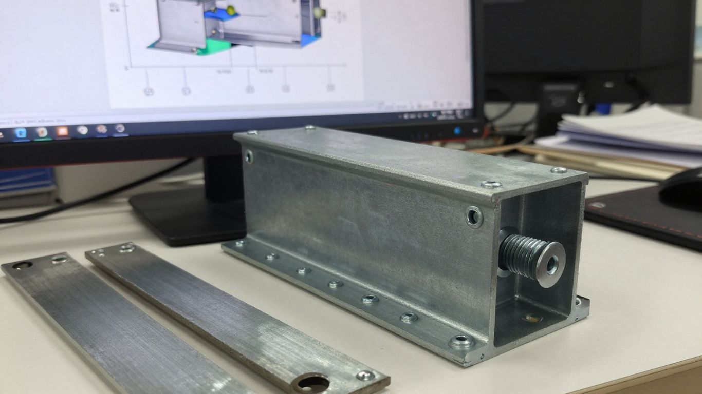
High-strength steel models are particularly sensitive to the relationship between material law, imperfection amplitude, boundary conditions, and failure criterion. A visually detailed mesh can still give a misleading answer if the load path is incomplete or the material curve is unsupported by evidence. The model should be as detailed as the decision requires, and no more.
Selecting elastic, plastic, and multilinear material models
An elastic model is suitable for many serviceability, stiffness, and initial load-distribution studies. It cannot, however, predict yielding, plastic redistribution, permanent deformation, or collapse. An elastic-perfectly plastic model can provide a useful idealization for some ultimate-limit-state investigations, but it may overstate or understate behavior where strain hardening is significant.
A multilinear or nonlinear curve is more suitable when the analysis depends on post-yield response, plastic hinge development, local strain concentration, or connection rotation. The curve should define the transition from elastic behavior to yielding and then the hardening range in a form the solver interprets correctly. True stress–strain and engineering stress–strain data should not be mixed without conversion.
Representing the yield plateau and strain hardening
Some structural steels show a yield plateau or a rounded transition rather than a perfectly sharp yield point. Whether that feature matters depends on the model’s purpose and the available test data. Omitting it may be reasonable in a global study, but it can influence local plastic strain, energy absorption, and the predicted sequence of yielding in a detailed model.
Strain hardening should be introduced with care. A curve that rises too steeply can make the model appear stronger and more ductile than the real product, while a curve that remains perfectly plastic may suppress reserve resistance. For cyclic or repeated loading, unloading and reloading rules may also be necessary; a monotonic curve alone is not a complete cyclic material model.
Defining realistic boundary conditions and load paths
Boundary conditions deserve as much attention as element selection. A fully fixed support can conceal connection flexibility, while a pinned idealization can exaggerate movement. The model should reflect bearing, contact, friction, diaphragm action, bolt pretension where relevant, weld continuity, and the stiffness of adjoining members when those features influence the result.
Loads should be introduced through the same physical path expected in the structure. Point loads applied to a single node can create artificial peaks; distributed or coupled loading may be more appropriate. Construction stages, support release, temperature effects, and self-weight activation can also matter when the final state depends on erection history.
Choosing shell, solid, or beam elements for the design objective
Beam elements are efficient for global frames and preliminary studies, provided the section properties, releases, offsets, and connection assumptions are appropriate. Shell elements are often useful for plates, webs, flanges, stiffeners, and buckling modes where through-thickness detail is not the main question. Solid elements become valuable around complex joints, thick plates, contact interfaces, and three-dimensional stress states.
The choice should follow the failure mechanism being investigated. A global beam model may identify force demand, while a refined shell or solid submodel examines a connection detail. Results from the local model then need compatible boundary conditions and a clear explanation of how they relate to the global structure. The FEA reporting guidance is a useful reminder that reproducibility depends on communicating these choices, not merely displaying a contour plot.
Stability and nonlinear analysis challenges
Stability is often the decisive issue when high-strength steel is used to reduce member dimensions. Greater yield strength can increase the theoretical resistance while leaving elastic buckling behavior broadly unchanged, narrowing the margin between instability and material yielding. Real members also contain imperfections and residual stresses that are not visible in an ideal geometry. A credible analysis therefore treats stability as an interaction between material, geometry, fabrication, and loading.
Combining global, distortional, and local buckling modes
A member may experience flexural, flexural-torsional, or lateral-torsional buckling at the global level while its plates undergo local buckling. Thin-walled sections can also distort, changing the relationship between flange and web restraint. These modes may interact, and the first eigenmode is not necessarily the governing nonlinear collapse shape.
The analysis should begin with a mode review rather than a blind reliance on the lowest eigenvalue. Section classification and code checks provide a baseline, while eigenvalue and nonlinear analyses can reveal coupled behavior or sensitivity to restraint. For complex sections, a refined model may be warranted where the interaction changes the design decision.
Introducing geometric imperfections from eigenvalue results
Perfect geometry usually produces an unrealistically optimistic response. A common approach is to extract relevant eigenmodes and scale them to credible fabrication or erection tolerances before running a geometrically nonlinear analysis. The selected mode shapes and amplitudes should be justified rather than chosen only because they produce the lowest capacity.
Multiple imperfection patterns may be needed when global and local modes compete. Sensitivity runs can show whether the conclusion is stable across plausible shapes and amplitudes. This is especially important for slender members, thin plates, and systems where small deviations change contact or load sharing.
Accounting for residual stresses and fabrication tolerances
Residual stresses from rolling, cutting, forming, and welding can trigger earlier yielding or alter buckling development. Their distribution is rarely known exactly, so models typically use idealized patterns based on fabrication knowledge, measurements, or conservative assumptions. The objective is not to create false precision but to test whether the structural conclusion survives credible variation.
Fabrication tolerances should be considered alongside residual stress rather than as unrelated checks. A member that is acceptable in isolation may be more sensitive after connection fit-up, splice installation, or temporary bracing is included. Inspection results can also inform whether the as-built condition remains within the model’s assumed range.
Using second-order and material nonlinear analysis appropriately
Second-order analysis captures additional moments caused by deformation, while material nonlinearity captures stiffness changes and yielding. They address different effects and may need to be combined for members with significant axial force and lateral displacement. Solver settings should include suitable increments, convergence tolerances, contact behavior, and a method for tracing instability where appropriate.
Nonlinear results should not be reduced to a single ultimate load without examining the response path. Sudden stiffness loss, localized yielding, contact changes, or numerical instability may each have different meanings. A useful interpretation distinguishes physical failure from a model limitation and checks whether the result is consistent with independent design calculations.
Connections, welds, and failure-critical details
The connection often controls whether the selected steel grade can be used efficiently. Increasing the resistance of a connected member does not automatically increase the resistance or ductility of its bolts, welds, plates, bolts holes, stiffeners, or supporting components. In high-strength systems, a brittle or poorly detailed connection can undermine the benefit of a lighter member. The connection model should therefore be related directly to the intended failure hierarchy.
Modeling bolt groups, slip, bearing, and prying action
A simplified rigid connection may be acceptable for a global model, but it cannot describe slip, bolt-group force redistribution, local bearing, tear-out, or prying action. Detailed models may need contact interfaces, bolt pretension, friction coefficients, nonlinear bolt behavior, and material failure criteria. The level of detail should match whether the question concerns service slip, ultimate resistance, fatigue, or ductile rotation.
Bolt-hole clearances and installation tolerances can affect the initial response. Where the connection is part of a braced or moment-resisting system, small changes in stiffness may also alter global force distribution. Hand checks remain valuable for screening the detailed model and identifying whether a contour peak corresponds to a real limit state.
Evaluating welded joints and heat-affected zones
Welded joints require attention to weld metal, parent material, geometry, residual stress, and the heat-affected zone. The local properties may not be identical to the nominal plate properties, particularly when the joint is highly restrained or the grade requires controlled heat input. A solid or refined shell model can be appropriate for investigating stress flow, effective throat behavior, and local yielding.
The analysis should be paired with the qualified welding procedure and inspection plan. A numerical stress concentration is not by itself a weld acceptance criterion, and a nominally low stress does not eliminate the need to check fracture, fatigue, or workmanship requirements. Where test data are available, they can help calibrate the local representation.
Capturing stress concentrations around openings and stiffeners
Openings, cope cuts, access holes, attachments, and stiffener ends interrupt the force flow and can create local peaks. Mesh refinement around these details should be based on a convergence study and on the chosen interpretation of stress. Singular nodal peaks should not be treated as physical failure loads without considering averaging, structural stress, strain, or a relevant local resistance model.
Detail geometry should include weld returns, radii, gaps, and plate offsets when those features govern the result. At the same time, unnecessary geometric complexity can obscure the main behavior and make the model difficult to audit. A staged approach—global model, local submodel, then detail assessment—usually gives a more useful engineering record.
Linking connection behavior to the global structural model
Connection stiffness, strength, and deformation capacity can change the response of the complete frame. If a local model shows meaningful slip or rotation, those characteristics should be represented in the global model through springs, nonlinear links, or another defensible idealization. Treating every connection as perfectly pinned or perfectly rigid can hide demand redistribution.
The interface between models should preserve force, displacement, and rotational conventions. Results need to be checked at the same load combinations and construction stages. This connection between local and global analysis is where engineering judgment is most visible: the model must simplify, but it must not simplify away the mechanism being assessed.
Validating and interpreting FEA results in practice
An FEA result becomes useful when another engineer can understand how it was produced, test its sensitivity, and relate it to a design decision. The basic finite element analysis stages of preprocessing, solution, and post-processing are simple to describe, but each contains choices that can materially change the outcome. Validation should therefore be planned before the final run, not added as a report appendix. It should address both numerical quality and physical plausibility.
Establishing mesh-convergence and sensitivity checks
Mesh convergence should focus on the quantities used to make the decision: displacement, reaction, buckling load, plastic zone, connection rotation, or a defined stress measure. Refining the entire model uniformly is often inefficient. Instead, refine regions with steep gradients, contact, holes, welds, or expected localization, then compare the response across progressively finer meshes.
Sensitivity checks should also vary uncertain inputs such as material curve, imperfection amplitude, residual stress pattern, friction, support stiffness, and load introduction. A result that changes materially under small plausible variations should be reported as sensitive. That does not make the analysis useless; it identifies where additional testing, detailing, or conservatism may be needed.
Comparing numerical predictions with hand calculations and testing
Hand calculations provide an essential scale check. Member resistance, Euler or code buckling estimates, connection capacities, equilibrium, and limiting deflections can reveal incorrect units, releases, section properties, or boundary conditions. The comparison need not match exactly, especially for a detailed model, but the difference should have an engineering explanation.
Physical testing may be appropriate for novel details, unusual fabrication, or high-consequence decisions. Test planning should define geometry, material characterization, imperfections, instrumentation, loading, and failure criteria before results are available. The FEA validation guide also reflects a broader principle: numerical simulation is most valuable when it helps refine decisions before costly testing, not when it is used to avoid all independent evidence.
Assessing fire, fatigue, corrosion, and accidental-load scenarios
The selected grade and model should be reviewed against scenarios beyond the basic room-temperature static case. Fire exposure changes material strength and stiffness with temperature, while fatigue depends on stress ranges, detail categories, cycles, and weld quality. Corrosion can reduce thickness and alter local slenderness, and accidental actions may require a different response target, including robustness or controlled deformation.
These scenarios should not be appended mechanically to an otherwise unrelated model. Fire analysis may require thermal coupling and protection assumptions; fatigue assessment may require carefully extracted stress ranges; corrosion may call for reduced geometry; and accidental-load analysis may require alternate load paths. The objective and acceptance criteria should be stated separately for each scenario.
Reporting assumptions, limitations, and design decisions clearly
A professional report should record geometry, material sources, section properties, mesh type and size, contacts, supports, loads, combinations, imperfection assumptions, residual stresses, solver controls, convergence behavior, and post-processing methods. It should also distinguish calculated results from engineering interpretation. Clear reporting allows reviewers to reproduce the important parts of the analysis and see where judgment entered the process.
For Singapore work, the report should identify the adopted SS EN 1993 provisions, relevant National Annex assumptions, authority or client requirements, and the role of the analysis within the endorsed design. Aman Engineering Consultancy provides professional engineering consultancy and design and engineering endorsement aligned with international standards; any project-specific endorsement remains dependent on the submitted design, evidence, and applicable authority requirements. The final conclusion should state not only what the model predicts, but also what it does not establish.
Conclusion
High-strength steel from S460 to S690 can offer meaningful structural efficiency in Singapore when the grade is selected as part of a complete design and delivery strategy. The opportunity is balanced by local buckling, ductility, weldability, connection behavior, supply constraints, imperfections, and nonlinear response. Sound FEA considerations begin with a clear engineering question and end with validation, transparent assumptions, and code-aligned professional judgment.
Frequently Asked Questions
Is S690 always better than S460 for a structural member?
No. S690 provides higher nominal yield strength, but buckling, deflection, connection capacity, weldability, toughness, cost, and availability may govern. The most suitable grade is the one that improves the complete structural solution.
Does higher-strength steel make a member stiffer?
Generally, no. Structural steel grades have broadly similar elastic modulus, so higher yield strength does not proportionally increase elastic stiffness. Deflection, vibration, and buckling checks remain necessary.
What is the main FEA challenge for high-strength steel?
The principal challenge is representing the interaction of material behavior, imperfections, residual stresses, boundary conditions, and instability. A stronger material model alone cannot correct an unrealistic structural model.
When should a nonlinear FEA model be used?
Nonlinear analysis is appropriate when yielding, post-buckling, contact, large deformation, connection slip, or collapse behavior affects the design decision. An elastic model may be sufficient for stiffness or initial load-distribution studies.
How should local buckling be checked?
Local buckling should be assessed using plate slenderness, section classification, code provisions, and, where necessary, shell or solid FEA. Relevant imperfections and boundary restraint should be represented when they influence the result.
Are high-strength steel welds more difficult to design?
They can require more carefully controlled procedures, consumables, heat input, preheating, inspection, and qualification. The weld and heat-affected zone must be checked as part of the complete load path.
What should an FEA report include?
It should state the objective, geometry, material data, mesh, supports, loads, contacts, imperfections, solver controls, convergence checks, validation comparisons, limitations, and the design decision supported by the analysis.