
Key Takeaways
Generative design can widen the range of structural steel concepts considered, but it does not replace engineering judgment or code-based verification.
- AI and FEA-driven topology optimization connects computational exploration with structural performance checks.
- Reliable results depend on accurate loads, supports, material data, mesh settings, and design boundaries.
- Steel-specific connection, stability, fabrication, and erection requirements must shape the optimization from the beginning.
- Several alternatives should be compared for strength, stiffness, cost, constructability, carbon, and lifecycle value.
- Production adoption requires documented assumptions, review checkpoints, coordinated models, and engineer approval.
Understanding AI and FEA-driven topology optimization
Generative design and topology optimization approach structural steel components as systems of forces, constraints, and material rather than as fixed shapes alone. The process can explore arrangements that may be difficult to find through manual trial and error, while finite element analysis provides the structural basis for judging them. The result is not automatically a final design; it is a group of engineering candidates that must still be interpreted, detailed, and verified. For a useful overview of the shift from refining an existing form to creating new alternatives, see this discussion of structural optimization concepts.
How generative design differs from conventional optimization
Conventional optimization usually begins with a known geometry and adjusts dimensions, thicknesses, member sizes, or selected parameters. Generative design starts with a defined design space and boundary conditions, then searches for multiple viable arrangements within those limits. AI may help identify patterns from previous solutions or guide the search toward promising regions, but the quality of its recommendations remains tied to the assumptions and examples used. A recent overview of AI-supported topology research illustrates how learned surrogates can assist FEA-based exploration without removing the need for physics-based checks.
The distinction matters for steelwork because a mathematically efficient form may not correspond to a standard rolled section, a practical plate assembly, or a connection that a fabricator can inspect and weld. Generative outputs are therefore best treated as early design evidence. Engineers must translate the geometry into a coherent load path and then test that interpretation using appropriate structural models, codes, and construction assumptions.
The role of finite element analysis in structural performance
FEA divides a component or assembly into elements and estimates its response to specified loads and restraints. Depending on the model, it can provide information about stress, displacement, strain, reaction forces, vibration, buckling, or nonlinear behavior. In topology optimization, those calculations are repeated as material is added, removed, or redistributed, so the solver is not merely checking a finished shape; it is helping define which shapes deserve further consideration.
The analyst still has to decide whether the model captures the real engineering problem. A misplaced restraint can make a weak concept appear sound, while an unrealistic point load can create an artificial hotspot. Contact behavior, weld flexibility, bolt slip, residual stress, geometric imperfections, and plate slenderness may also be relevant. Physics remains the control point: AI can accelerate a search, but it cannot make incomplete boundary conditions reliable.
Design objectives: weight, stiffness, strength, and cost
A useful optimization has a hierarchy of objectives rather than a single instruction to remove material. Weight reduction may be attractive, but excessive flexibility can cause serviceability problems, and a component with a difficult fabrication sequence may cost more despite using less steel. Strength, stiffness, stability, fatigue life, connection behavior, procurement, and inspection should be considered together where they affect the project decision.
The objective function should also distinguish between constraints and preferences. A maximum displacement or required resistance may be mandatory, while lower mass or fewer parts may be ranked goals. Multi-objective studies can expose sensible compromises: one option may be lightest, another may use a familiar plate thickness, and a third may offer the best balance of fabrication time and structural reserve.
When topology optimization is appropriate for steel components
Topology optimization is most useful when the component carries a defined set of forces and has meaningful freedom to change shape. Brackets, transfer components, lifting points, stiffened plates, truss nodes, equipment supports, and specialized connections can be suitable candidates. It is less helpful when the geometry is already governed by architectural space, standardized rolled sections, access requirements, fire protection, or strict detailing conventions.
The method also needs a clear scale. It can identify a broad load path, but it may not resolve every bolt, weld access requirement, erection tolerance, or local imperfection accurately. For large building systems, topology findings may inform the arrangement of members and plates rather than directly produce a fabrication model. That distinction prevents an attractive density plot from being mistaken for a construction document.
Preparing structural steel models for optimization
Preparation often determines whether an optimization study produces insight or simply produces a sophisticated-looking error. The model should describe the component’s actual role, including how forces enter, where the component is restrained, and which surfaces must remain available for connection or inspection. Before any automated search begins, the design team should agree on the governing load cases, applicable standards, material grade, and expected manufacturing route.
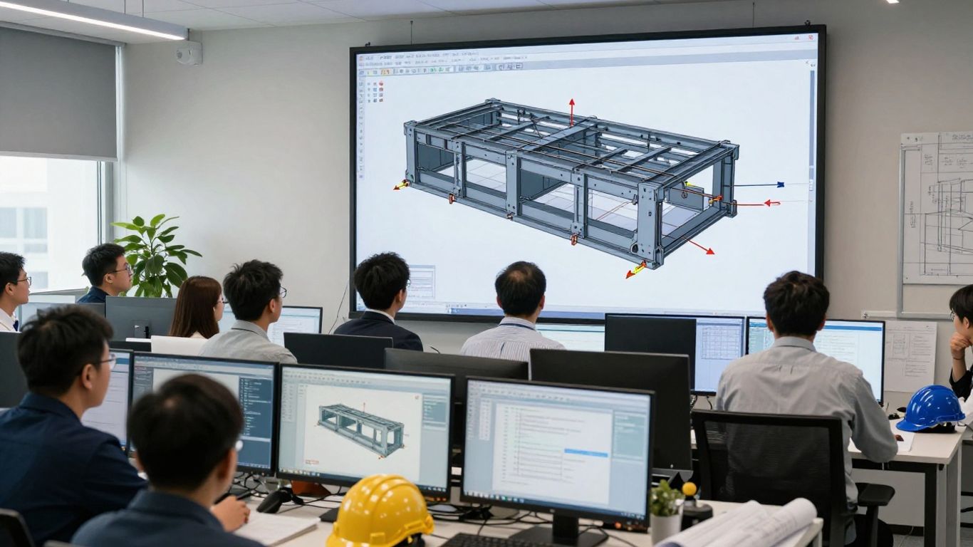
A simplified model can be appropriate for concept generation, provided its simplifications are explicit and later checked. The analytical representation should not silently discard a connection eccentricity, a weak axis, or a construction-stage load that governs the real component.
Defining loads, supports, load combinations, and design space
Loads should be applied where they enter the physical component, not merely where they are convenient in the software. Permanent, imposed, wind, equipment, thermal, erection, impact, and accidental actions may need separate treatment. Load combinations should reflect the governing design standard and the component’s actual use, including combinations that control serviceability rather than ultimate resistance.
Supports deserve equal attention. A fixed boundary may be a reasonable abstraction for a welded interface, but it can be misleading where bolts, slotted holes, bearing surfaces, or flexible adjacent members govern the response. The design space should then identify what may change and what must remain. Connection plates, inspection clearances, access zones, and interfaces with other systems commonly belong outside the optimization region.
Selecting material properties for structural steel
The material model should match the analysis stage. Elastic modulus, Poisson’s ratio, density, yield strength, tensile strength, and relevant thermal properties are basic inputs, but they are not always sufficient. Nonlinear analysis may require a stress-strain relationship, while fatigue assessment requires appropriate detail categories and stress-range assumptions. Material grades should be selected from project specifications and applicable standards rather than from a convenient default library value.
Differences between nominal and design properties should be controlled carefully. The analyst should record whether the model uses characteristic values, nominal values, or factored design values, and should avoid mixing these conventions within one optimization loop. If corrosion allowance, fire condition, temperature effects, or weld-affected properties matter, they should be stated as separate assumptions and carried into the validation model.
Applying symmetry, manufacturing, and non-design regions
Symmetry can reduce computation and encourage balanced solutions, but it should only be used when the geometry, loading, supports, and intended fabrication genuinely permit it. Manufacturing constraints can be introduced through minimum member sizes, draw directions, extrusion or milling limits, overhang controls, or preferred plate orientations. These restrictions usually make the output less visually dramatic, but more useful.
Non-design regions protect the parts that cannot move during optimization. Typical examples include connection faces, bolt holes, weld lands, bearing areas, lifting points, and interfaces with concrete or equipment. A practical set of protected zones often includes:
- Connection surfaces that transfer the primary forces.
- Bolt and weld locations required by the intended detail.
- Inspection, drainage, and maintenance clearances.
- Erection and lifting interfaces needed on site.
These regions give the solver a realistic envelope. They also make it easier for an engineer to explain why material remains in apparently low-stress areas.
Managing mesh quality, convergence, and model simplification
Topology results are sensitive to element size, element type, filtering, and convergence criteria. A coarse mesh may hide a narrow load path, while a very fine mesh can consume time without improving the decision. Mesh refinement should therefore be concentrated around load introductions, holes, fillets, abrupt thickness changes, and connection interfaces rather than applied without purpose.
A converged objective value does not automatically mean a converged design. The shape should be reviewed at more than one mesh density, and the final reconstructed geometry should be re-meshed independently. Model simplification can remove tiny features that cannot be fabricated or that have no meaningful structural effect, but simplification must not erase a critical notch, connection eccentricity, or stability mode.
Building a generative design workflow
A generative workflow is most effective when it separates exploration from approval. Early runs can be broad and relatively fast, while later stages progressively add code checks, manufacturing detail, connection behavior, and project-specific coordination. This staged approach prevents the team from spending excessive time validating concepts that were never feasible to build.
The workflow should also preserve a record of inputs and outputs. Each candidate needs a clear relationship to its objective values, constraints, load cases, material assumptions, and geometry version. Without that record, the apparent variety of alternatives can become difficult to compare or defend.
Translating engineering requirements into optimization objectives
Engineering requirements should be expressed in terms the optimization can evaluate. “Use less steel” is incomplete; a stronger definition might set a mass preference subject to displacement limits, resistance requirements, minimum thickness, stability criteria, and protected connection zones. Requirements that cannot be evaluated numerically should still be written as screening rules for the engineering team.
The design brief should identify what is fixed, what may vary, and what constitutes failure. It should also clarify whether the study concerns a component, a connection region, or a larger structural system. Clear definitions reduce the risk of optimizing a local part against loads that do not represent the behavior of the surrounding structure.
Generating and screening multiple design alternatives
One candidate rarely captures the best project solution. Different volume fractions, stiffness targets, symmetry assumptions, manufacturing directions, and load combinations can produce significantly different forms. Screening should begin with non-negotiable criteria, then proceed to performance and delivery considerations. A visually smooth shape is not a sufficient reason to retain it.
The screening record can be concise, but it should show why each option was advanced or rejected. It is useful to identify whether a candidate failed because of excessive displacement, buckling, inaccessible welds, unusual plate thicknesses, poor material availability, or an uncertain load path. That information improves the next optimization cycle rather than merely discarding the result.
Using parametric studies to evaluate design sensitivity
Parametric studies test how strongly the outcome depends on assumptions. Useful variables may include load magnitude, load position, support stiffness, plate thickness, material grade, mesh density, minimum feature size, or the relative weighting of mass and stiffness. The goal is not to create endless variants, but to find which assumptions materially change the engineering decision.
Sensitivity results can reveal whether a proposed geometry is stable across reasonable uncertainty. If a small change in support stiffness completely redirects the load path, the component may need a more conservative configuration or a better-defined interface. If several reasonable inputs lead to similar forms, confidence in the underlying concept is improved, although formal validation is still required.
Connecting AI recommendations with engineer-led decisions
AI recommendations should be presented with their inputs, limits, and relevant performance evidence. Engineers need to know whether a result came from a trained surrogate, a conventional iterative solver, a rule-based filter, or a combination of methods. They should also be able to reproduce the governing analysis or identify where independent verification is needed. A useful explanation is tied to load paths and constraints, not just to a ranking score.
A related discussion of FEA-driven design iteration describes how AI can help explore broader parameter spaces while keeping simulation central to the decision. For structural steel, that principle is especially important because project acceptance depends on traceable engineering reasoning, code compliance, and buildability—not only on computational efficiency.
Applying steel-specific design and manufacturing constraints
Steel components occupy a space between continuous mathematical forms and discrete fabrication practice. A topology result may distribute material elegantly, yet still require plates, sections, welds, bolts, coping, lifting, coating, and inspection. Bringing those realities into the optimization early usually produces less fragile concepts and shortens the path to detailing.

The manufacturing route should be discussed with the fabricator where possible. Workshop capacity, available plate sizes, cutting methods, welding qualifications, machining limits, transport dimensions, and site access can all influence which alternative is genuinely efficient.
Preserving bolted and welded connection zones
Connections should be treated as structural regions, not as empty boundaries around an optimized body. Bolt groups require edge distances, pitch, gauge, wrench access, hole tolerances, and suitable bearing areas. Welded details require access, weld length, continuity, termination, inspection, and control of distortion. These requirements may force material to remain where a purely stress-based result would remove it.
The connection model should reflect the intended force transfer. An idealized rigid tie may conceal prying, slip, local flange bending, block shear, or weld-group effects. Similarly, a smooth organic transition may create a detail that cannot be welded continuously or inspected reliably. Preserving a conventional connection envelope often makes later design checking clearer.
Accounting for buckling, slenderness, and local stability
Strength under a simple static load is only one part of steel behavior. Thin plates, slender webs, compression branches, and open sections may buckle before reaching their nominal material resistance. Global, local, distortional, and lateral-torsional modes can interact, particularly when the optimized form does not resemble a familiar section.
The optimization should therefore include minimum dimensions, stiffening provisions, imperfection assumptions, or explicit stability checks where appropriate. Eigenvalue results can help identify likely modes, but they are not a complete nonlinear stability assessment. The final engineering model may need geometric imperfections, residual stress assumptions, contact, and second-order effects.
Designing for cutting, forming, machining, and fabrication
Fabrication constraints begin with the material form and the equipment available. Flat plate parts may be cut and welded, while other components may be rolled, bent, forged, or machined. Minimum radii, tool access, heat input, distortion control, tolerances, and surface treatment can influence the final geometry. The best optimization setting is the one that reflects the selected production route.
Designers should also consider handling and erection. A lighter component may be easier to lift, but a more complex shape may require temporary bracing or a custom jig. Part count, weld length, dimensional inspection, and repair access can dominate the practical cost of a seemingly efficient design.
Converting organic optimization results into manufacturable profiles
The conversion from an organic density field to a steel profile is an engineering reinterpretation. Curves can become tapered plates, ribs, rolled members, welded box sections, or a combination of standard components. The converted form should preserve the principal load paths while introducing consistent thicknesses, accessible joints, drainage, corrosion protection, and reasonable tolerances.
At this point, the design should be checked against the project’s detailing conventions and fabrication documentation requirements. Tekla Structures is documented in the source material as a platform used for structural steel shop drawings, including assembly drawings, single-part drawings, connection details, erection drawings, material lists, and bolt lists. Those outputs belong to the detailing and fabrication phase; they should not be confused with the optimization result itself.
Validating optimized steel components with FEA
Validation begins after the candidate has been reconstructed as a credible engineering component. The final model should include the geometry that will actually be designed, including realistic joints, thicknesses, restraints, and load introduction details. It is often useful to compare the reconstructed model with the simplified optimization model so that any change in behavior is visible.
No single analysis type answers every question. Linear static analysis is efficient for initial comparisons, while nonlinear, stability, fatigue, dynamic, and accidental-load studies may be needed for acceptance. The level of analysis should follow the component’s risk, behavior, governing standard, and consequences of failure.
Running linear static analysis for initial performance checks
Linear static analysis provides a useful first check of reactions, stress distribution, displacement, and load-path continuity. It can show whether the reconstructed form broadly retains the behavior that motivated it. The analyst should review both global results and local concentrations, distinguishing genuine structural concerns from singularities created by idealized restraints or sharp geometry.
Results should be checked against code-based resistance and serviceability criteria using the correct design combinations. A candidate that performs well under one load case may still fail under a transverse action, a reversed load, a construction condition, or a combination that produces a different force path.
Using nonlinear analysis for plasticity and large deformation
Nonlinear analysis becomes relevant when material yielding, contact changes, geometric nonlinearity, instability, or large deformation affects the response. It can reveal reserve capacity, progressive redistribution, or failure mechanisms that a linear model cannot represent. However, nonlinear results are sensitive to mesh, imperfections, constitutive data, solution controls, and the treatment of connections.
The analysis should be built incrementally and interpreted by an engineer familiar with its assumptions. A smooth load-displacement curve is not proof of safety if the model suppresses a relevant buckling mode or uses unrealistic ductility. Independent checks and suitable benchmark cases help establish confidence in the result.
Evaluating fatigue, vibration, and serviceability requirements
A component that meets ultimate strength requirements may still be unsuitable if it vibrates, deflects excessively, or accumulates fatigue damage. Repeated crane loads, machinery excitation, wind effects, traffic, thermal cycling, or fluctuating connection forces can make stress range more important than peak static stress. Welded details and abrupt transitions deserve particular attention because local stress concentrations may govern fatigue life.
Serviceability checks should reflect how the component is used and perceived. Displacement limits, natural frequencies, acceleration, rotation, noise, drainage, and alignment may all matter. These criteria should be defined before alternatives are ranked so that a light but flexible candidate does not appear superior by default.
Verifying robustness under accidental and off-design loading
Robustness means examining credible conditions outside the primary design case. Depending on the application, these may include impact, dropped loads, fire-related loss of strength, unusual erection states, temporary support removal, wind reversals, or local damage. The objective is not to predict every event, but to determine whether the component has an unacceptable single-point vulnerability.
Off-design checks can also test whether the optimized load path is excessively specialized. A concept that performs only under one exact force direction may be inappropriate where load uncertainty is high. The final review should identify the assumptions that matter most and specify where additional protection, redundancy, or monitoring is required.
Evaluating design alternatives beyond weight reduction
Weight is easy to display and easy to overvalue. A complete comparison asks what the project gains and what it gives up when a candidate is selected. The answer may involve fewer pieces, faster erection, lower transport demand, better access, improved durability, or simpler procurement rather than a minimum mass alone.
Decision-making should remain transparent to the client, fabricator, checker, and approving authority. A compact comparison matrix can make the trade-offs visible without pretending that all criteria have equal importance.
Comparing mass savings with strength and stiffness performance
Each alternative should be compared using common load cases, material assumptions, boundary conditions, and acceptance criteria. Useful measures include mass, maximum displacement, utilization, buckling factor, natural frequency, fatigue usage, connection demand, and reserve capacity. Reporting only the percentage of material removed hides whether performance has deteriorated near a critical limit.
The preferred option may therefore be heavier than the theoretical minimum. A modest mass increase can buy substantially better stiffness, simpler joints, greater tolerance to uncertain loading, or a more familiar fabrication sequence. Engineering value comes from the complete performance profile.
Assessing fabrication complexity, material availability, and cost
Cost assessment should include more than the price of steel. Cutting time, nesting, forming, machining, welding, inspection, coating, rework, transport, temporary works, and erection labor may all change with geometry. Material availability also matters: a design that depends on unusual grades, thicknesses, or proprietary processes may introduce schedule and procurement risk.
A conventional plate-and-stiffener arrangement can sometimes outperform a highly specialized component when shop capacity and site conditions are considered. The comparison should include fabrication feedback early enough to change the design rather than merely document an objection after the geometry is fixed.
Reviewing embodied carbon and lifecycle implications
Reduced steel mass can lower the embodied impacts associated with material production and transport, but the assessment should include additional weld metal, machining, coatings, scrap, replacement, and maintenance. Durability and inspection access influence whether a component remains useful over its intended life. A design that is difficult to repair may carry a different lifecycle profile from a slightly heavier but accessible alternative.
Lifecycle review should use project-specific data where available. Recycled content, regional supply, reuse potential, disassembly, and future adaptation can all affect the outcome. The comparison is strongest when environmental indicators are presented beside structural and economic criteria rather than treated as a separate afterthought.
Documenting design assumptions, constraints, and approval evidence
Every chosen alternative should have a concise decision record. It should identify the design space, loads, supports, combinations, material properties, mesh strategy, optimization settings, manufacturing assumptions, rejected options, and validation analyses. Revision control is essential because a small change to a connection or load case can invalidate an earlier ranking.
Approval evidence should include the engineer’s review, calculation files, model versions, drawings, checks, and responses to comments. Where international projects are involved, the record should also identify the governing requirements, such as applicable ACI, BS, SS, or Eurocode provisions. This makes the result easier to review and support for authority submission or independent checking.
Implementing generative design in structural engineering practice
Moving from a successful study to routine practice requires more than selecting software. Teams need a process that connects conceptual analysis, detailed design, fabrication, BIM coordination, checking, and approval. Responsibilities should be clear: who defines the problem, who owns the model, who reviews the assumptions, and who authorizes release for detailing or construction.
The most dependable implementation is gradual. Begin with components whose loads and interfaces are well understood, compare the automated process with established calculations, and expand only when the team can explain both the benefits and the limitations.
Integrating optimization with CAD, BIM, and detailing platforms
An optimized concept must move through several representations without losing design intent. Geometry, material data, connection zones, member identifiers, analysis results, and revision status should remain traceable as the concept enters CAD, BIM, analysis, and detailing environments. Interoperability checks are necessary because a visually similar model may not contain the same analytical assumptions.
Tekla Structures is described in the source material as supporting advanced steel detailing, custom component development, automated drawing production, and integration with fabrication machinery. Used at the appropriate detailing stage, such capabilities can help turn an approved steel concept into coordinated fabrication information. The optimization itself still needs a controlled handoff and an independent design check.
Establishing review checkpoints and model governance
Governance should define when a model is exploratory, analytical, checked, approved, or released. Checkpoints can occur after boundary-condition definition, initial optimization, candidate screening, geometry reconstruction, code verification, coordination, and detailing. At each point, the reviewer should be able to identify the model version and the evidence supporting the decision.
Access control, naming conventions, data retention, and change tracking may seem administrative, but they protect the technical record. If an AI-assisted recommendation cannot be traced to its inputs and evaluation criteria, it should not be treated as an approved engineering decision.
Addressing explainability, data quality, and AI limitations
AI systems can reproduce patterns in their training data, including gaps, biases, or unsuitable assumptions. A model trained on mechanical components may not understand the detailing culture, code requirements, erection sequence, or connection behavior of a structural steel project. Sparse or inconsistent project data can produce confident recommendations with weak engineering foundations.
Explainability should therefore be practical. The team should ask which loads drove the form, which constraints eliminated alternatives, how sensitive the result is to boundary conditions, and where the recommendation falls outside known examples. Human review is not a final ceremonial step; it is part of defining whether the output is relevant at all.
Creating a repeatable process for production-ready components
A repeatable process begins with a standard project brief and ends with a controlled package of analysis, design, detailing, and approval evidence. Templates can define minimum inputs, required load cases, mesh checks, manufacturing questions, code reviews, and file naming. Lessons from completed studies should be fed back into those templates rather than kept as informal team knowledge.
Production readiness also means knowing when not to optimize. If the component has uncertain loads, an unstable interface, severe fire exposure, unusual fatigue demand, or no practical fabrication route, conventional engineering development may be the safer path. Generative design is most valuable when it gives engineers better choices, not when it is used simply because automation is available.
Conclusion
Generative design can help structural engineers explore steel components more broadly, but its value depends on disciplined inputs, realistic constraints, FEA validation, and practical detailing. When AI-assisted exploration is connected to code compliance, fabrication knowledge, lifecycle judgment, and documented approval, topology optimization becomes a useful part of engineering practice rather than an isolated software exercise.
Frequently Asked Questions
What is topology optimization for structural steel?
Topology optimization is a computational method that redistributes material within a defined design space to meet selected structural objectives and constraints. For steel components, the result usually requires engineering interpretation before it can become a conventional fabricated form.
How does generative design differ from topology optimization?
Topology optimization commonly modifies material distribution within an established space, while generative design can explore a broader range of new forms and alternatives. In practice, the terms may overlap, and both require clearly defined loads, supports, objectives, and manufacturing limits.
Why is FEA necessary in generative design?
FEA estimates how a proposed geometry responds to loads and restraints. It supplies the physics-based performance information needed to compare alternatives, identify failure modes, and verify the reconstructed component.
Can topology optimization produce a fabrication-ready steel part?
Usually, it produces a conceptual or intermediate geometry rather than a finished fabrication package. Engineers and detailers must add connection details, standard thicknesses, tolerances, access, inspection provisions, and construction information.
What steel constraints should be included early?
Connection zones, minimum thickness, buckling limits, slenderness, weld access, bolt access, cutting and forming limits, lifting points, corrosion protection, and transport restrictions are common early constraints. The exact set depends on the component and its fabrication route.
Is the lightest design always the best design?
No. The lightest candidate may have excessive deflection, poor fatigue performance, difficult connections, high fabrication cost, limited material availability, or weak resilience under uncertain loading. A balanced evaluation is normally more useful than mass reduction alone.
How should an optimized component be approved?
Approval should follow documented engineering review, suitable FEA, code-based resistance and serviceability checks, stability and fatigue assessment where relevant, fabrication review, coordination, and controlled release of the final design and detailing information.