
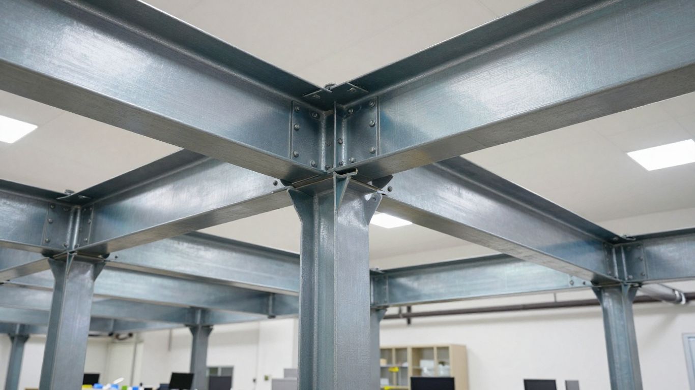
Key Takeaways
Reliable FEA modelling depends less on visual complexity than on sound engineering judgment. The most useful model is one that represents the real load path, material behavior, restraints, imperfections, and limitations clearly.
- Idealize the structure according to the behavior being investigated.
- Use verified steel grades, section properties, and nonlinear material data.
- Apply supports, restraints, loads, and combinations as they occur physically.
- Check mesh sensitivity, stability modes, and nonlinear convergence.
- Verify results against equilibrium, hand calculations, codes, and observed behavior.
Start with a reliable structural idealization
Every finite element model is an approximation, so the first decision is what the model must explain. A global model may need member forces and overall drift, while a local model may need bolt bearing, weld behavior, or plate yielding. The idealization should preserve the important load paths without adding detail that cannot be interpreted. A useful introduction to the underlying finite element method can help clarify why the choice of element is itself an engineering assumption.
Choosing between beam, shell, and solid elements
Beam elements are often efficient for slender members whose cross-sections remain suitable for one-dimensional idealization. Shells are more appropriate when plate bending, local buckling, welding, or connection geometry matters. Solid elements can resolve three-dimensional stress states, but they demand careful geometry, contact definitions, and computational resources. The wrong element type can produce a polished contour plot while omitting the behavior that controls failure.
Representing member geometry, offsets, and eccentricities
Centerlines rarely meet exactly as the physical steelwork does. Beam offsets, flange elevations, gusset-plate positions, bracket eccentricities, and bearing locations can change moments and force distribution. Define these relationships explicitly rather than relying on coincident nodes to imply a connection. Where detailing information is available, Tekla Structures models can provide geometry that captures bolts, welds, and connection details for coordination with the analytical idealization.
Modeling connections, releases, and contact behavior
A pinned, rigid, semi-rigid, or slipping connection does not merely change a node setting; it changes the structure’s stiffness and load path. Releases should correspond to actual restraint, and contact should distinguish compression transfer from separation or sliding. Check whether a joint transfers moment, shear, axial force, or only a selected combination, and avoid using rigid links to conceal missing connection mechanics.
Including secondary members and load-path components
Purlins, girts, bridging, stiffeners, diaphragms, collector members, and temporary bracing may provide restraint even when they are not primary gravity members. Omitting them can exaggerate buckling lengths or shift forces into members that would not carry them alone. Conversely, adding every visible component can create artificial stiffness. Include secondary components when they participate in the load path or stability system, and state when they have been idealized rather than modeled explicitly.
Avoid inaccurate material and section properties
Material data should describe the steel actually specified, not a convenient default from the software library. Section dimensions, thicknesses, grades, weld zones, and fabrication conditions can all affect stiffness and resistance. Errors here propagate through every load case, so a converged solution is not evidence that the inputs are correct.
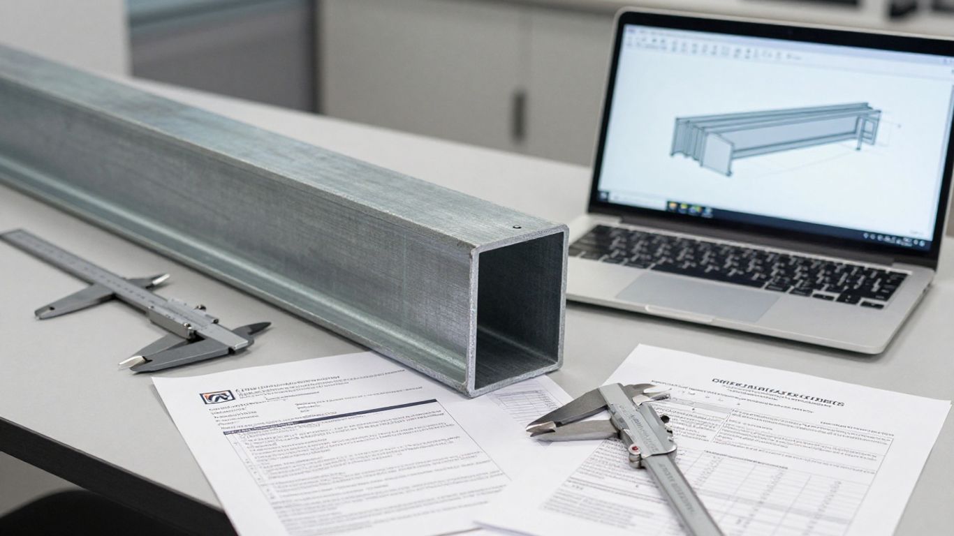
Using inappropriate steel grades or stress–strain curves
Confirm the specified grade, thickness-dependent strength, elastic modulus, Poisson’s ratio, and design temperature assumptions before analysis. A linear elastic curve may be adequate for a serviceability study, but it cannot describe plastic redistribution or collapse. Similarly, a nominal yield stress should not be substituted for a complete curve when the result depends on post-yield behavior.
Ignoring residual stresses and fabrication effects
Rolled and welded members can contain residual stresses, initial out-of-straightness, locked-in distortion, and heat-affected regions. These effects influence first yield and buckling, especially in slender plates and welded built-up sections. They need not be represented in every global model, but omitting them should be a deliberate decision tied to the purpose of the analysis and the conservatism of the interpretation.
Defining section properties for slender or built-up members
Gross section properties can overstate the effective stiffness and resistance of slender elements after local buckling begins. Built-up members also require attention to plate connectivity, stitch welds, lacing, spacers, and shear transfer between components. For a global analysis, effective properties may be suitable where prescribed by the governing design method; for local studies, the plates and their restraints often need direct representation.
Accounting for yielding, strain hardening, and material nonlinearity
Plastic analysis requires a constitutive model that matches the intended level of prediction. Define yield behavior, hardening, unloading assumptions, and failure limits consistently with the available test data or accepted design guidance. The distinction between elastic analysis and collapse analysis should be visible in the report, because a stress exceeding yield is not automatically a numerical error or a proof of failure.
A practical material review can be organized around the following checks:
- Confirm the grade and thickness range against the specification.
- Compare section dimensions with drawings and fabrication information.
- Identify whether residual stress or weld softening is relevant.
- Match the constitutive law to the required limit state.
These checks are simple, but they prevent a solver from giving false confidence to an otherwise inaccurate model.
Apply realistic boundary conditions and loading
Boundary conditions are part of the structural model, not a mathematical convenience added after geometry is complete. Real supports have stiffness, friction, tolerances, and local flexibility. Loads also enter through bearing areas, floor systems, diaphragms, hangers, and connection hardware rather than appearing uniformly at arbitrary nodes.
Avoiding overconstrained supports
Fully fixed supports can suppress translations and rotations that the real foundation or base plate permits. The resulting reactions may look orderly while member forces are substantially distorted. Use springs, contact, coupling constraints, or explicit support components where their stiffness matters, and inspect reaction distributions for signs of unintended restraint.
Representing bracing and diaphragm restraint correctly
A brace restrains only the degrees of freedom that its geometry and connection can develop. A diaphragm may distribute load in-plane without acting as a rigid body out of plane. Model these distinctions carefully, particularly in frames where lateral-torsional buckling or load sharing depends on restraint spacing. If a diaphragm is idealized as rigid, document why that assumption is reasonable for the structure and load case.
Applying loads at physically meaningful locations
Apply loads to the surfaces, nodes, or members through which they enter the structure. Point loads placed at a beam centroid can miss flange-local effects, while a uniform pressure on an analytical surface may bypass purlins or sheeting. Include load eccentricity where it creates torsion or prying, and avoid double-counting self-weight when both density and an explicit gravity load are active.
Combining design loads and load cases consistently
Separate characteristic, factored, service, accidental, and fatigue cases according to the governing standard. Do not combine already factored outputs a second time, and ensure that signs, directions, tributary areas, and dynamic factors remain consistent. A load-combination table is particularly useful when several analysts or software packages contribute to the same project.
Control mesh quality and convergence
Mesh refinement should follow the physics of the problem rather than a desire for a uniformly dense model. Element formulation, aspect ratio, through-thickness resolution, integration scheme, and transition quality can matter as much as nominal element size. A coarse global mesh may be entirely reasonable, provided local behavior is not being inferred from it.

Refining the mesh around holes, welds, and connections
Local changes in geometry and load transfer require smaller elements than prismatic regions. Refine around bolt holes, cope cuts, weld toes, bearing zones, stiffener ends, and abrupt thickness changes when those locations are part of the question being asked. The refinement should extend far enough to recover a stable structural response rather than ending at the first row of coarse elements.
Avoiding distorted elements and abrupt mesh transitions
Highly skewed, warped, or stretched elements can degrade accuracy and create misleading stress patterns. Check the quality metrics recommended for the chosen formulation, especially near curved edges and contact interfaces. Transition from fine to coarse mesh gradually, and use geometry partitioning when automatic meshing cannot preserve meaningful element shapes.
Checking mesh sensitivity and result stability
A mesh study should compare the response that supports the engineering decision, not only the maximum contour value. Track reactions, deflections, member forces, plastic zones, buckling loads, or averaged local stresses as the mesh changes. A useful comparison can be summarized as follows.
| Quantity reviewed | Coarse mesh | Refined mesh | Interpretation |
|---|---|---|---|
| Global displacement | Initial estimate | Stable value | Indicates overall stiffness sensitivity |
| Support reaction | Equilibrium check | Stable distribution | Tests load transfer and constraints |
| Local stress | Often elevated or noisy | More resolved | Requires a defined averaging method |
| Plastic zone | Limited resolution | Clearer extent | Helps assess collapse mechanism |
The purpose is not to force every value to become identical. It is to show that the reported conclusion is stable, or to explain why a local peak remains mesh-dependent and should not be treated as a directly converged design quantity.
Understanding convergence failures in nonlinear analysis
Nonlinear convergence can fail because of a genuine instability, an abrupt material transition, excessive load increments, poor contact initialization, or an ill-conditioned constraint system. Reduce the increment size, review contact and boundary conditions, and inspect the deformed shape before changing solver tolerances blindly. Numerical difficulty often contains structural information, but only when the model is checked rather than repeatedly forced to converge.
Capture steel stability and geometric imperfections
Steel members rarely fail through a perfectly straight, perfectly centered path. Initial crookedness, residual stress, connection flexibility, and load eccentricity can reduce the capacity predicted by an ideal elastic model. Stability analysis therefore needs both the correct mode shapes and a credible way to introduce imperfections.
Modeling global buckling and second-order effects
Global flexural, torsional, and lateral-torsional buckling modes should be compatible with the member’s actual restraint and loading. Second-order effects become significant when axial force acts through a displaced geometry, so a first-order result may understate moments and drift. Use geometric nonlinearity when the expected deformation changes equilibrium, and verify that the model’s effective length assumptions are not being duplicated through artificial restraints.
Including local and distortional buckling modes
Thin webs, flanges, lips, stiffened plates, and built-up components can buckle locally before the member reaches a global instability. Distortional modes may involve relative movement of elements within a cross-section and can be missed by a simple beam model. Shell idealizations, suitable imperfections, and adequate through-width mesh resolution are needed when these modes govern the assessment.
Generating realistic initial imperfections
Imperfections can come from measured fabrication data, tolerance limits, scaled eigenmodes, or prescribed geometric shapes. The chosen amplitude and mode should be stated, along with whether residual stresses are included separately. A visually dramatic imperfection is not automatically conservative; it may trigger an unrealistic mechanism or suppress the mode that would occur in the physical member.
Combining eigenvalue buckling with nonlinear analysis
Eigenvalue buckling is useful for identifying potential instability patterns and estimating elastic critical loads, but it does not by itself predict ultimate resistance. A nonlinear analysis can use suitable eigenmodes as initial imperfections while including material yielding, geometric nonlinearity, and relevant contact behavior. Compare the resulting mechanism with code checks and engineering expectations instead of treating the lowest eigenvalue as a direct safety factor.
Represent connections and stress concentrations responsibly
Connections deserve a level of detail matched to the decision under review. A global frame model may represent a joint with springs or idealized rigid regions, while a connection assessment may require plates, bolts, welds, contact, and local plasticity. Mixing these purposes in one model can make the results difficult to interpret.
Deciding when connection details require shell or solid modeling
Use shell elements when plate behavior, bolt-hole effects, weld layout, or local buckling is central to the question. Solids are justified when three-dimensional bearing, through-thickness stress, weld geometry, or contact pressure must be resolved. For a global response, a calibrated spring or component idealization may be more transparent than a highly detailed connection that has not been validated.
Avoiding artificial stress peaks at sharp corners
An infinitely sharp re-entrant corner can create a mathematical stress singularity that does not exist in the fabricated detail. Add realistic radii, weld transitions, contact areas, or a reporting distance where appropriate. Do not select a single unaveraged peak at a singular location as the basis for a member-wide conclusion; examine the surrounding stress field and the physical failure mode.
Modeling bolts, welds, bearing, and slip behavior
Bolts can be represented with connector elements, pretensioned fasteners, or detailed solids depending on the required result. Welds may be idealized by compatible connectivity or modeled explicitly when throat stress and local failure are being studied. Bearing, clearance, friction, and slip should be included when they influence stiffness, redistribution, or the sequence of yielding.
Interpreting hot-spot stresses and singularities
Hot-spot stress methods are intended to extract a structural stress at a defined location or extrapolation path, not to report the largest integration-point value. Establish the stress measure, location, averaging rule, and mesh basis before comparing results. For fatigue or fracture-sensitive assessments, the interpretation must remain tied to the detail category and the applicable design procedure.
Verify, validate, and interpret FEA modelling results
A finite element result is an engineering argument supported by calculations, not a substitute for one. Verification asks whether the equations were solved correctly for the stated model; validation asks whether the model represents the physical system well enough for its intended use. Both require review of the model, not just its colored contours.
Checking reactions, equilibrium, and load paths
Sum reactions and compare them with applied loads, including moments where relevant. Review whether forces travel through the intended members, diaphragms, collectors, and supports, and investigate unexpected reaction sharing. Small discrepancies may arise from numerical tolerances, but unexplained imbalance usually signals a modeling or extraction error.
Comparing results with hand calculations and design codes
Use simple calculations to establish orders of magnitude for axial force, bending, shear, deflection, bearing, and buckling. Compare the relevant limit states with the governing standards, including section classification, lateral-torsional buckling, column stability, local plate checks, and connection resistance. STAAD Pro provides comprehensive structural analysis capabilities, but software output still requires independent engineering review and code-based interpretation.
Reviewing deformation patterns and failure mechanisms
The deformed shape often reveals more than a peak stress plot. Check whether buckling occurs in the expected direction, whether contact opens or closes plausibly, and whether yielding spreads through a credible mechanism. Unexpected rigid-body motion, isolated element collapse, or deformation concentrated at a constraint is a reason to revisit the model before accepting the result.
Documenting assumptions, solver settings, and model limitations
A defensible report records geometry sources, element types, material curves, imperfections, supports, contacts, load combinations, mesh studies, solver controls, convergence criteria, and result-extraction methods. It should also identify what the model does not assess. For projects involving broader ground-movement interaction, PLAXIS 3D is documented for true three-dimensional modeling of complex geometries, corner effects, irregular shapes, and non-uniform loading; that scope should not be assumed to replace a structural steel model or its verification.
Clear documentation makes later revisions safer. Another engineer can see which assumptions are fixed, which are sensitive, and which conclusions should not be transferred to a different load case or detail.
Conclusion
Good structural steel FEA modelling is disciplined approximation: choose the right idealization, represent the physical restraints and material behavior, resolve the details that matter, and test whether the conclusions remain stable. When numerical results are checked against equilibrium, hand calculations, codes, and plausible failure mechanisms, FEA becomes a useful engineering tool rather than a source of attractive but unreliable plots.
Frequently Asked Questions
What is the most common error in structural steel FEA modelling?
The most common error is usually an inaccurate structural idealization, particularly incorrect restraints, releases, or load paths. A refined mesh cannot correct a model that does not behave like the real structure.
Should every steel structure be modeled with shell elements?
No. Beam elements are efficient for many global frame analyses, while shells and solids are reserved for local plate, connection, contact, or stress-concentration questions. The element choice should follow the behavior being assessed.
How fine should the mesh be near a connection?
The mesh should be fine enough to resolve the geometry and load transfer, with gradual transitions away from the detail. Sensitivity studies should track engineering quantities such as deformation, reactions, plastic zones, or defined averaged stresses.
Are eigenvalue buckling results sufficient for design?
No. Eigenvalue analysis identifies ideal elastic instability modes, but it does not generally include imperfections, yielding, contact changes, or post-buckling behavior. Nonlinear analysis and code checks are often needed for capacity assessment.
Why do nonlinear analyses fail to converge?
Failure may result from real instability, large load increments, material discontinuities, contact changes, poor mesh quality, or conflicting constraints. Review the deformed shape and model definitions before adjusting solver settings.
Can a maximum stress from an FEA contour be used directly?
Not always. Peaks at point loads, sharp corners, rigid constraints, and weld toes may be singular or mesh-dependent. Use an appropriate averaging, extrapolation, or hot-spot procedure tied to the relevant design method.
What should an FEA report contain?
It should describe the geometry, elements, materials, supports, loads, combinations, imperfections, contacts, mesh checks, solver settings, convergence, verification calculations, results, and limitations. The report should make the scope of each conclusion clear.