

Key Takeaways
A reliable BIM to FEA workflow depends less on a perfect file exchange than on clear engineering decisions before, during, and after the transfer.
- Define analysis objectives, responsibilities, model uses, and exchange rules before modeling begins.
- Separate physical BIM geometry from the simplified analytical geometry required by the solver.
- Check coordinates, connectivity, materials, releases, supports, units, and load assumptions after every transfer.
- Treat FEA results as controlled design information rather than overwriting the BIM model without review.
- Maintain revision control, approval gates, ownership, and measurable QA/QC throughout the project.
Define the BIM-to-FEA workflow before modeling begins
BIM and finite element analysis serve different purposes, even when they describe the same structure. The BIM model records coordinated physical information for design, construction, and operations, while the FEA model idealizes that structure to study behaviour under defined assumptions. A successful BIM-to-FEA process therefore begins with decisions about purpose and responsibility, not with an export button.
Establish analysis objectives, design responsibilities, and model uses
Start by stating what the analysis must answer. Typical questions concern gravity and lateral response, member sizing, vibration, stability, staged construction, connection behaviour, or a local stress concentration. Each question can require a different level of geometric detail, idealisation, mesh density, and validation effort.
Assign responsibility for the physical model, analytical model, loads, combinations, design checks, and final engineering endorsement. The person coordinating geometry is not automatically responsible for interpreting structural results. A responsibility matrix prevents an apparently complete model from concealing an unreviewed assumption.
Choose the authoring and analysis platforms for the project
Platform selection should follow the project’s information requirements, structural system, codes, team capability, and expected exchanges. Tekla Structures is documented in the source material as an authoring platform used for detailed structural models and steel shop drawings, while Revit is identified as an authoring platform for discipline-specific BIM models and IFC deliverables.
The analysis environment should be selected according to the type of structural question being investigated. A building-level frame or shell model may be appropriate for global response, while a local solid or contact model may be necessary for a connection, anchorage, bearing region, or unusual load path. The decision should be recorded rather than left to individual preference.
Set up naming conventions, coordinates, units, and classification systems
A shared coordinate system is the quiet foundation of a dependable exchange. Agree on project north, survey coordinates, levels, grids, local member axes, unit conventions, and the treatment of offsets. A model can appear visually correct while still producing incorrect forces if axes or units have shifted.
Naming should be stable across disciplines and software. Element IDs, levels, grids, materials, sections, load cases, and revisions need predictable patterns. Classification systems aligned with ISO 12006 and structuring principles aligned with ISO 81346 can support traceability across the project lifecycle, particularly where asset data will later be reused.
Document exchange requirements in the BIM execution plan
The BIM execution plan should define who authors each element, what information is required at each stage, which formats are accepted, and how often exchanges occur. It should also specify tolerance rules, analytical modelling assumptions, issue numbering, approval gates, and the procedure for rejecting an unreliable export.
Pre- and post-contract BIM execution plans, modelling standards, naming conventions, QA/QC audits, compliance reports, and risk registers are useful governance instruments. A clear plan makes the exchange a repeatable project process rather than an informal handoff between software users.
Prepare BIM models for structural analysis
A coordinated BIM model is not automatically ready for structural analysis. Physical objects often contain fabrication detail, finishes, penetrations, and relationships that are valuable for construction but unnecessary or harmful in a global analytical model. Preparation is the stage where the team decides what structural information must survive and what can be simplified.

The prepared model should remain traceable to the authoring model while being fit for its intended analysis. Model purpose governs detail: a global building model, a connection model, and a construction-stage model should not be forced into one identical representation.
Separate physical geometry from analytical geometry
Physical geometry describes where an object exists and how it is built. Analytical geometry describes centre lines, reference surfaces, nodes, idealised supports, and effective stiffness. Beams may become frame lines, slabs may become shell areas, and complex physical intersections may become a deliberate node or link condition.
Keep the relationship between the two representations explicit. Record offsets, eccentricities, member insertion points, diaphragm assumptions, and any effective-width or stiffness modifications. This allows an engineer to explain why the analytical model differs from the coordinated physical model without treating the difference as an error.
Simplify members, connections, slabs, and openings appropriately
Remove detail that does not affect the question being studied, but do not remove geometry that controls load transfer. Small bolts, weld beads, trims, and architectural layers may be excluded from a global model; major openings, transfer structures, discontinuities, and connection eccentricities usually require deliberate treatment.
Slabs can be represented as diaphragms, shell elements, or another suitable idealisation depending on the analysis objective. Openings must be reflected where they alter stiffness, mass, force flow, or diaphragm action. Connections should be represented through releases, rigid zones, springs, links, or detailed submodels rather than by assuming every intersection is fully rigid.
Validate materials, sections, releases, supports, and load-bearing elements
Before export, inspect whether every structural element has a meaningful material and section assignment. Confirm that the model distinguishes load-bearing members from reference or non-structural objects, and review member releases, offsets, support conditions, slab thicknesses, wall properties, and reinforcement information where relevant.
Loads deserve a separate review. Identify which loads are physically modelled, which are applied in the solver, and which are intentionally excluded. Confirm that self-weight is not counted twice and that imposed, wind, seismic, temperature, construction, and equipment actions are assigned to the correct analytical entities.
Apply model quality checks before exporting to an FEA solver
Quality checks should be systematic and repeatable. They can include geometry validation, duplicate detection, tolerance checks, unconnected-node searches, property completeness, object classification, and comparison against design documents. A model audit should produce an actionable report, not merely a pass or fail label.
A useful pre-export review follows a short sequence because omissions are easier to find when the order is consistent:
- Confirm coordinates, levels, grids, units, and model origin.
- Check that structural elements are classified and have valid properties.
- Identify duplicate, intersecting, disconnected, or unexpectedly offset objects.
- Compare model quantities and member counts with the design basis.
- Record exclusions, simplifications, assumptions, and the export revision.
After the review, issue a frozen exchange package with a clear revision identifier. The receiving analyst should know exactly which model was checked and which known limitations remain.
Transfer geometry and data between Tekla, Revit, and FEA software
Interoperability is not simply a matter of choosing the newest file format. Each exchange method preserves some information, transforms some information, and loses other information. The team must understand those boundaries before relying on imported geometry or properties.
Compare IFC, direct links, APIs, and solver-specific import formats
IFC can provide a useful neutral exchange route when multiple disciplines and platforms are involved, particularly where the receiving system supports the required entity types. Direct links may reduce manual steps but can create a stronger dependency on software versions, plug-ins, and mapping behaviour. APIs and scripts offer control and repeatability when the project has stable rules and capable technical ownership.
Solver-specific formats may preserve analysis properties more effectively than a general BIM exchange, but they can also make the workflow less portable. The appropriate choice depends on whether the priority is broad coordination, property fidelity, automation, or a controlled one-way transfer. Research on BIM and FEA interoperability also identifies node placement and force-transfer ambiguity as persistent concerns; this BIM and FEA integration research provides useful background for framing those risks.
Map BIM elements to SAP2000, ETABS, and ANSYS entities
Mapping should be defined as an engineering rule set. A physical column may become a frame element, a wall may become a shell or solid region, and a slab may become a shell, diaphragm, or a deliberately excluded object. The mapping must also state how analytical nodes are created at intersections, offsets, supports, and discontinuities.
SAP2000 is identified in the source material as structural analysis software that can receive BIM-derived information through an IFC-based conversion workflow. ANSYS may be selected for a detailed local finite element investigation when the geometry, contact, material behaviour, or stress distribution requires a finer representation than a building-level model. The platform name does not remove the need to verify every mapping assumption.
Preserve section properties, materials, metadata, and element relationships
Geometry is only one part of the transfer. Section dimensions, material grades, local axes, member orientation, releases, offsets, identifiers, level information, and relationships between elements should be checked independently. A visually convincing import can still contain a default material, an incorrect orientation, or a missing release.
Use mapping tables that show the source property, destination property, conversion rule, and verification method. Where a property has no direct destination, record the loss and assign an owner to recreate or approve it. This is especially important for information needed later for detailing, compliance, construction coordination, or handover.
Manage unsupported objects, duplicate elements, and translation errors
Not every BIM object has a meaningful analytical equivalent. Architectural finishes, complex embedded items, fabrication components, and unusual solids may need to be excluded, simplified, or transferred as reference geometry. Exclusions should be deliberate and documented rather than silently discarded by an importer.
Translation errors often appear as duplicate members, gaps between nodes, overlapping shells, reversed axes, broken relationships, or unexpected changes in units. Compare object counts and key dimensions before and after import, then inspect high-risk areas visually. If the translation cannot be reconciled, stop the analysis update and issue an exchange query instead of repairing the file invisibly.
Build and calibrate the analytical model in the FEA solver
Once geometry and data arrive in the solver, the model still requires engineering construction. Imported objects are inputs, not proof that the analytical system is complete. The analyst must establish connectivity, restraints, stiffness assumptions, loading, and the checks needed to determine whether the model behaves as intended.
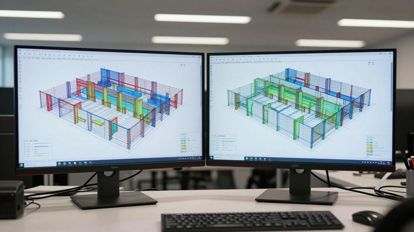
Calibration here means comparing the analytical idealisation with the design basis and expected structural behaviour. It does not mean adjusting the model until a preferred result appears. Changes should have a stated reason, an approver, and a record in the analysis revision.
Convert BIM geometry into nodes, frames, shells, solids, and links
The element type should follow the structural role and the analysis objective. Nodes define connectivity and load transfer; frames represent line-like members; shells represent surfaces where membrane and bending action matter; solids capture three-dimensional stress states; links and springs describe discrete or flexible relationships.
Pay particular attention to offsets and intersections. A beam that visually meets a column may not share the same analytical node, and two shells that touch may not transfer force if their connectivity is incomplete. Use mesh controls and compatibility checks to avoid creating a model that is geometrically dense but mechanically disconnected.
Define boundary conditions, diaphragms, contacts, and connection behavior
Boundary conditions should reflect the intended support idealisation, not merely the nearest physical object. Define translational and rotational restraints, foundation flexibility, diaphragm action, contact interfaces, and connection stiffness where they influence response. Over-restraint can hide movement and inflate forces, while under-restraint can create unrealistic mechanisms.
For interfaces and connections, document whether the behaviour is fixed, pinned, semi-rigid, frictional, compression-only, tension-only, or otherwise nonlinear. Local studies may require contact pairs, bolt representations, weld idealisations, or material nonlinearity. These choices should be consistent with the level of evidence available from the design and detailing information.
Apply load cases, combinations, construction stages, and design assumptions
Load cases should be assembled from a controlled design basis. Define self-weight, permanent actions, imposed actions, environmental actions, temperature effects, equipment, accidental actions, and construction conditions as applicable to the project. Combinations must match the governing code and the purpose of the check.
Construction stages can change stiffness, support conditions, load paths, and the sequence in which actions are introduced. If staging is relevant, model it explicitly or explain why a simplified envelope is acceptable. Record code references, factors, mass sources, damping assumptions, and any effective stiffness values so another engineer can reproduce the analysis.
Decide when detailed ANSYS modeling is preferable to building-level analysis
A building-level model is generally suited to global actions such as overall drift, reactions, member forces, modal response, and stability trends. A detailed local model becomes more appropriate when three-dimensional stress concentrations, complex contact, nonlinear material response, unusual geometry, anchorage, or connection behaviour controls the decision.
The detailed model should inherit verified geometry and boundary actions from the global model, while its scope remains limited to the question being answered. A refined mesh is not automatically a better model; it is useful only when the material law, contacts, constraints, loads, and boundary conditions are equally defensible.
Validate results and coordinate design changes
Validation should happen at several levels, from visual inspection to structural response. The purpose is not to prove that a result is correct in an absolute sense, but to identify whether the model, assumptions, and outputs are credible for the stated use. Unexpected behaviour is a prompt for investigation, not a reason to hide an inconvenient result.
Perform visual, geometric, and connectivity checks after import
Compare the imported analytical model with the source BIM view, grids, levels, elevations, member locations, slab boundaries, openings, and major transfer elements. Then inspect connectivity using solver tools and targeted views around supports, discontinuities, and changes in framing.
The visual review should be supported by numerical checks. Count members and nodes, compare bounding dimensions, inspect duplicate or orphan elements, and verify local axes. Small discrepancies may be acceptable if documented; unexplained discrepancies should block the next design decision.
Compare reactions, masses, stiffness, and natural periods with expectations
Global response checks provide early warning of modelling errors. Compare total mass, gravity reactions, centre of mass, approximate stiffness, support reactions, and natural periods with hand calculations, prior design stages, or reasonable engineering expectations. Large differences can indicate missing loads, duplicated self-weight, incorrect units, or unintended restraints.
These checks are particularly valuable after a new export or mapping-table revision. They should be recorded with the model revision and assumptions used for the comparison. A short numerical audit often reveals problems that a polished three-dimensional view will not show.
Review critical forces, deflections, stresses, and stability behavior
Review results against the analysis objectives rather than scanning every contour equally. Identify critical members, floors, walls, connections, supports, and local regions, then check forces, deflections, stresses, vibration, buckling, second-order effects, and stability behaviour as relevant.
Interpretation must include the cause of a result. A high force may be realistic, or it may arise from a rigid constraint, duplicate element, poor mesh transition, or incorrect load path. Engineering judgement, independent checks, and code-based design review remain necessary even when the software reports a clean run.
Track discrepancies between the BIM model and the analytical model
Maintain a discrepancy register linking each issue to a source object, analytical object, revision, responsible person, status, and resolution. Typical entries include changed member sizes, moved grids, altered supports, revised openings, changed materials, and analysis-only idealisations.
Use issue logs and coordination meetings to close discrepancies deliberately. The record should distinguish between a source-model change and an approved analytical assumption. That distinction prevents a temporary analysis simplification from being mistaken for construction geometry.
Synchronize FEA results with the BIM model
Returning analysis information to BIM can improve coordination, but not every solver output belongs in the authoring model. The exchange should be selective, purposeful, and controlled. BIM remains useful when it carries information that other disciplines can understand and act upon, rather than becoming a container for every contour plot.
Determine which analysis results should return to Tekla or Revit
Results suitable for return may include approved member sizes, design statuses, governing forces, reinforcement requirements, connection inputs, support reactions, or parameters needed for coordination. Highly detailed stress fields and solver-specific diagnostics are often better retained in the analysis record and linked through a report or reference identifier.
The receiving team should agree on the information requirement before publication. For example, a fabricator may need approved member and connection information, while a coordination team may need revised geometry, clearances, and status fields. Returning only decision-ready information keeps the BIM model usable.
Update member sizes, reinforcement, connections, and design parameters
Updates should follow the design approval process. A revised section, reinforcement arrangement, or connection detail must be checked for constructability, interfaces, quantities, and downstream effects before it becomes the current coordinated information.
Where structural models include connection details, reinforcement, embedded items, and penetrations, changes should be reflected consistently across drawings and schedules. The person applying the update should preserve the source of the decision and identify which analysis revision supports it.
Use controlled model exchanges instead of uncontrolled overwrites
Never treat synchronization as a blind replacement of one file with another. Publish a new revision, compare changed objects, review property mappings, and obtain approval before updating the shared model. A one-way exchange may be safer than a two-way exchange when the responsibilities and conflict rules are not mature.
Controlled exchanges also preserve the ability to reproduce earlier results. Archive the exported file, mapping table, solver model, input assumptions, result package, and approval record together. If a later question arises, the team can reconstruct what was known at the time of the decision.
Coordinate revisions with clash detection and constructability reviews
A structural change can affect architecture, MEP routing, fire protection, fabrication, temporary works, and access. Federated model reviews should therefore follow significant analytical updates, with hard and soft clashes prioritised by severity and assigned for resolution.
Coordination meetings should examine the changed area, the reason for the change, and its effect on construction. Issue tracking in a structured format, supported by action logs and constructability reviews, helps ensure that an analytically sound revision does not create a practical site problem.
Govern, automate, and maintain the integrated workflow
The technical exchange is only one part of BIM to FEA integration. Long projects involve many revisions, contributors, software versions, and approval points. Governance provides the continuity needed to keep a model trustworthy when the original modeller or analyst is no longer available.
Use revision control, approval gates, and a single source of truth
Define the authoritative location for the physical model, analytical model, issued drawings, analysis inputs, and approved results. A single source of truth does not mean one file contains everything; it means the relationship between files, revisions, and decisions is unambiguous.
Approval gates can be placed before export, after import, before analysis issue, after design changes, and before coordinated publication. Each gate should have defined checks and an accountable approver. Avoid parallel spreadsheets and informal copies that force the team to reconcile competing statuses.
Automate repetitive exchanges with APIs, scripts, and mapping tables
Automation is most valuable for predictable work: extracting identifiers, checking properties, comparing quantities, generating issue lists, and applying approved mappings. APIs and scripts should support engineering review rather than bypass it. A fast transfer is still unreliable if the rules cannot be inspected or tested.
Begin with a small, repeatable exchange and add complexity only after the basic checks are stable. Version scripts and mapping tables with the project data, test them against representative geometry, and provide a clear exception report when an object cannot be processed.
Assign ownership for model changes, analysis updates, and QA/QC
A responsibility matrix should name people or defined roles for authoring, export, import, analysis, checking, coordination, and approval. Ownership must include the decision to reject a transfer when the quality evidence is inadequate.
QA/QC should cover both model content and engineering interpretation. A model auditor can identify missing properties and broken connectivity, while an independent checker reviews assumptions, methods, stability, dynamic behaviour, and critical design outputs. Keeping those roles visible reduces the chance that a software warning becomes someone else’s problem.
Measure workflow performance through errors, rework, and coordination KPIs
Useful measures include rejected exchanges, translation errors, duplicate or disconnected elements, unresolved issues, turnaround time, rework hours, and the age of open coordination actions. These indicators reveal where the workflow is actually failing instead of relying on general impressions.
Review the measures at project milestones and after major software or mapping changes. The goal is not to reward fewer reported errors; it is to find errors earlier, reduce repeated manual work, and improve the reliability of decisions made from shared digital information.
Conclusion
A dependable BIM-to-FEA workflow joins disciplined engineering judgement with disciplined information management. Clear objectives, suitable idealisation, verified exchanges, transparent assumptions, and controlled revisions allow BIM models and analytical models to support one another without pretending they are identical. For projects governed by international standards and detailed coordination requirements, that traceability is as valuable as the calculated result itself.
Frequently Asked Questions
What is BIM to FEA integration?
It is the controlled process of transferring relevant building information and geometry from a BIM environment into a finite element analysis model, validating the translation, performing analysis, and returning approved design information where useful.
Is a BIM model ready for analysis immediately after it is created?
Usually not. The model must be reviewed for analytical geometry, structural classification, materials, sections, connectivity, releases, supports, loads, units, and the level of detail required by the intended analysis.
Should physical and analytical models be identical?
No. They describe the same structure for different purposes. The analytical model often simplifies geometry and represents physical behaviour through idealised nodes, frames, shells, solids, links, restraints, and stiffness assumptions.
Which exchange format is best for BIM and FEA?
There is no universally best format. IFC, direct links, APIs, scripts, and solver-specific formats each offer different balances of portability, property preservation, automation, and version control. The project should select and document the method that fits its requirements.
How can imported analytical models be checked?
Use visual comparisons, coordinate and dimension checks, object counts, duplicate and orphan searches, connectivity reviews, property audits, mass and reaction comparisons, and checks of natural periods or other expected global responses.
Should all FEA results be written back into the BIM model?
No. Return only approved information that supports design coordination, detailing, construction, or handover. Detailed solver diagnostics and dense result fields can remain in the analysis package with a clear reference from the BIM information.
Who is responsible for validating a BIM-to-FEA exchange?
Responsibilities should be assigned in the project’s execution and quality plans. The authoring team, analyst, model coordinator, independent checker, and approving engineer may each have different duties, but no exchange should proceed without a named accountable reviewer.