
Introduction
Electrochemical chloride extraction (ECE) halting corrosion without breaking concrete is not a theoretical concept; it is a rehabilitation technique that has been applied to over 4 million ft² of concrete structures worldwide since its commercial introduction in the late 1980s, and has been widely adopted in practice with numerous projects completed. By applying an electric field across the concrete cover, ECE draws chloride ions away from the reinforcing steel and back toward a temporary external anode, restoring the passive protective film on the steel surface without any need to demolish sound material.
This article explains how ECE works, what controls its effectiveness, when it outperforms conventional repair, and what it takes to execute a project on an aging reinforced concrete structure in Singapore or the wider ASEAN region. The focus is on in-service structures (bridges, marine wharves, carparks, building façades) rather than new material formulations or generic repair mortars. The primary audience is asset owners, facility managers, structural engineers, and public agencies responsible for maintaining reinforced concrete structures exposed to chloride contamination from coastal salt spray, marine splash zones, or ponding water.
ECE works by connecting the steel reinforcement as a cathode, fixing a temporary anode mesh on the concrete surface with a saturated electrolyte, and running a DC electrical current for 2 to 8 weeks. Chloride ions migrate out of the concrete under the electric field, while the treatment generates hydroxyl ions at the steel surface during the electrolysis process, raising the local pH and re-passivating the reinforcement. Once the treatment concludes, ECE does not require ongoing electrical power; the treatment is carried out temporarily, and the steel remains passive in its restored alkaline environment.
What readers will learn:
-
How chloride-induced corrosion starts and why conventional patch repairs often fail within 3 to 7 years.
-
The electrochemical principles behind the ECE process and what physically changes inside the concrete during treatment.
-
A step-by-step overview of a typical ECE project on a real structure in Southeast Asia.
-
When ECE is suitable versus when to choose patch repair, cathodic protection, or partial reconstruction.
-
How AMAN Engineering Consultancy Pte Ltd can assess and implement ECE as part of a wider durability strategy.
Understanding Chloride-Induced Corrosion in Reinforced Concrete
Chloride ingress is the dominant cause of steel corrosion in reinforced concrete structures across Singapore and ASEAN. The region’s marine environment, year-round humidity of 70–90%, and temperatures between 25–35 °C accelerate the transport of chloride ions through the concrete cover to the reinforcement surface. Once the chloride concentration at the steel exceeds a threshold (typically 0.2% to 0.4% by weight of cement), the passive oxide film protecting the rebar breaks down, and active corrosion begins.
How Chloride Ions Reach the Reinforcement
Three transport mechanisms move chlorides through concrete. Diffusion occurs when a concentration gradient exists between the exposed surface and the interior; chloride ions move from high to low concentration through the pore network. Capillary suction pulls chloride-laden water into dry or partially saturated concrete during wetting cycles, common in structures exposed to tidal zones or monsoon-driven rain. Permeation forces chloride solution through concrete under hydrostatic pressure, relevant for submerged or water-retaining structures.
In Singapore, the exposure scenarios that matter most include coastal residential towers and hotels within 1–3 km of the shoreline, quay walls and jetties in direct marine splash zones, and podium carparks where wind-driven rain and ponding water concentrate salts on soffits and deck surfaces. Older pre-1990s structures often have cover depths below 20 mm and higher water-to-cement ratios, both of which accelerate chloride ingress. Newer code-compliant buildings typically specify 40–50 mm of cover depending on exposure class, but even these are not immune over a 50-year design life in aggressive environments.
Before considering electrochemical chloride extraction, engineers quantify the chloride profile using powder sampling at multiple depths, rapid chloride permeability testing (ASTM C1202), and half-cell potential mapping. These measurements establish whether chloride contamination at the reinforcement depth has reached or exceeded the corrosion threshold.
From Passive Film to Active Corrosion
Steel embedded in sound, uncarbonated concrete sits in a highly alkaline environment (pH ≈ 12.5–13). At this pH, a thin iron-oxide passive film forms on the reinforcement surface and prevents dissolution of the underlying metal. Chloride ions, when present in sufficient concentration at the steel surface, locally destroy this passive film by competitive adsorption and pit initiation.
The chloride threshold, expressed as a mass fraction of chloride to cement, typically falls in the range of 0.2% to 0.4%. The exact value depends on concrete alkalinity, moisture content, oxygen availability, and cover depth. In durability assessments, engineers compare measured chloride profiles against this threshold to judge whether a structure is at risk.
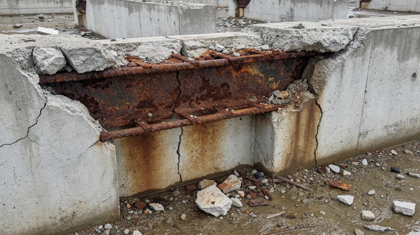
Once the passive film breaks down, corrosion proceeds through coupled electrochemical reactions. At anodic zones on the steel, iron dissolves (Fe → Fe²⁺ + 2e⁻). At cathodic zones, oxygen reduction (O₂ + 2H₂O + 4e⁻ → 4OH⁻) maintains electroneutrality. The resulting corrosion products (rust) occupy roughly 2–6 times the volume of the parent steel. This expansion generates internal stresses that cause longitudinal cracking along bars, delamination of the cover, and eventually spalling of concrete chunks. Because corrosion is an electrochemical process driven by ion transport and electron flow, it can also be mitigated or reversed with an electrochemical treatment.
Limitations of Conventional Repair Approaches
Conventional patch repair follows a predictable sequence: break out delaminated concrete with pneumatic hammers, clean or replace corroded rebar, apply repair mortar, and coat the surface. The repaired patch itself may perform well. The problem lies at the boundary between new and old material.
Chlorides remaining in the adjacent, untouched concrete create what corrosion engineers call the “incipient anode” effect. The freshly patched zone, now low in chlorides and high in alkalinity, becomes cathodic relative to the still-contaminated surrounding concrete. Corrosion accelerates at the patch perimeter, and new cracking typically appears within 3 to 7 years. The cycle repeats, each time requiring more concrete removal, more disruption, and more cost.
In live buildings (hospitals, malls, occupied residential blocks), patch repair also brings noise, dust, vibration, and multi-week closures of affected areas. ECE offers an alternative that directly tackles the root cause: chloride ions distributed throughout the cover zone, not just the visible damage at the surface.
What Is Electrochemical Chloride Extraction (ECE)?
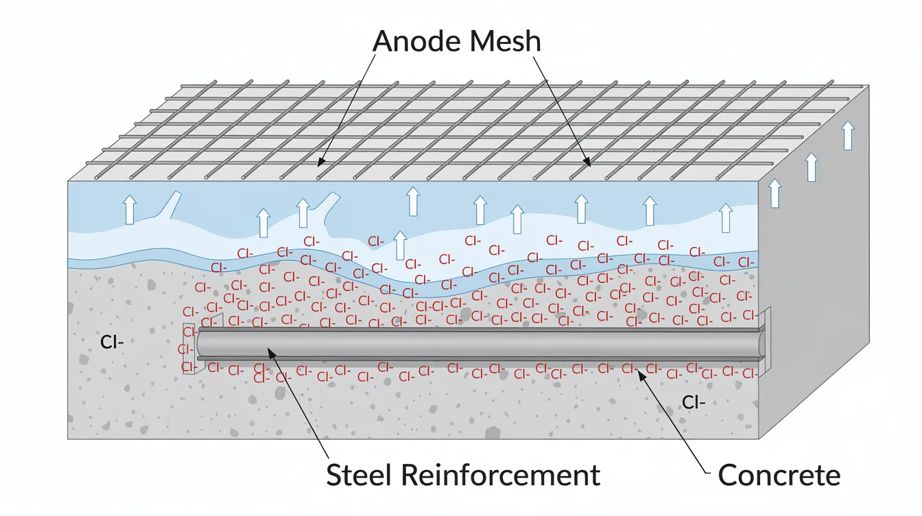
Electrochemical chloride extraction is a temporary electrochemical treatment that uses direct current (DC) to drive chloride ions out of contaminated reinforced concrete and toward an external anode mesh fixed on the concrete surface. At the same time, the process raises pH at the reinforcement by generating hydroxyl ions, restoring passivity of the steel. The technique is also referred to as electrochemical chloride removal, desalination of concrete, or simply electrochemical treatment in various standards and research literature.
ECE was first studied in the mid-1970s. The Norcure process was patented in Norway in 1985, and commercial availability of the Norcure process began in 1988. From 1988 to 1993, the Strategic Highway Research Program (SHRP) sponsored research on ECE across four field validation sites in the United States, including bridge decks, pilings, columns, and abutments. Electrochemical chloride extraction is a non-destructive rehabilitation technique for reinforced concrete; the concrete cover remains intact throughout.
Basic Electrochemical Principle Behind ECE
The electrical circuit in an ECE system consists of three elements. The steel reinforcement is connected to the negative terminal of a DC power supply and serves as the cathode. A temporary anode mesh (typically MMO-coated titanium) is placed on the concrete surface and connected to the positive terminal. An electrolyte, usually a sodium borate or alkaline buffer solution, saturates the space between the anode and the concrete.
When current flows, the applied electric field drives negatively charged chloride ions through the concrete pore structure away from the steel and toward the external anode. Simultaneously, hydroxyl ions (OH⁻) accumulate at the rebar surface through cathodic oxygen reduction, increasing local alkalinity and helping re-form the passive film on the steel. ECE restores the passivity of steel reinforcement by increasing local alkalinity at the reinforcement surface.
The process is temporary. Treatment time typically spans 2 to 8 weeks, after which the power supply and anode are removed. This distinguishes ECE from long-term cathodic protection systems, which require continuous power for the life of the structure.
Key Components of an ECE System
A complete ECE installation on site includes:
-
Power supply/rectifier: capable of maintaining constant current at controlled voltage, typically kept under 30–50 V to prevent paste damage and gas evolution.
-
Temporary anode mesh: MMO-coated titanium ribbons or mesh sheets fixed directly to the concrete surface with non-metallic fasteners.
-
Electrolyte distribution system: geotextile blankets or shallow ponding trays that keep the anode-concrete interface continuously moist with alkaline solution.
-
Electrical connections to reinforcement: drilled pockets exposing rebar for cable bonding, with continuity testing across all connected mats to ensure uniform current distribution.
-
Instrumentation: embedded reference electrodes, current/voltage data loggers, temperature sensors, and corrosion monitoring probes for real-time process control.
How ECE Compares to Other Electrochemical Methods
Electrochemical chloride extraction applies a relatively high current (impressed current densities for ECE range from 0.5 to 5 A/m²) over a short duration (weeks) to remove chlorides and restore passive conditions. Realkalisation is a similar temporary technique, but it targets carbonated concrete where the pH has dropped rather than cases of high chloride contamination. Impressed current cathodic protection (ICCP) operates at lower current densities over the entire remaining service life of the structure, keeping the steel polarised below the corrosion potential indefinitely; it requires permanent anodes, wiring, and a power supply that must be maintained and monitored for 20+ years.
The core distinction: ECE aims to return the concrete-steel system to a self-sustaining passive state so that no permanent electrical system is needed. ICCP accepts that the environment remains aggressive and compensates with continuous polarisation. The choice between them depends on the severity of contamination, the feasibility of removing the chloride source, and the owner’s appetite for long-term maintenance obligations.
How Electrochemical Chloride Extraction Works in Practice
Translating electrochemical principles into a field application requires careful control of current density, voltage, electrolyte pH, and treatment duration. Exceeding safe operating limits can soften cement paste, reduce bond strength, or produce gas at the electrodes. Staying within established ranges, supported by decades of research, keeps these side effects within acceptable bounds and delivers chloride removal efficiency ranging from 20% to 50% after treatment, with values obtained in studies reaching up to 52% of chlorides removed, while electrolyte and cement variables can influence removal efficiency.
Site Investigation and Feasibility Assessment
A detailed condition survey precedes any ECE design. Visual inspection and hammer-tap surveys map areas of delamination and spalling. Half-cell potential mapping and concrete resistivity measurements identify zones where active corrosion is underway. Cover meters and rebar scanners confirm reinforcement layout and cover depth. Chloride profiling by powder sampling at 10–15 mm depth increments quantifies contamination at and beyond the steel.
ECE is generally considered when chloride content at the reinforcement exceeds the corrosion threshold but the concrete cover is otherwise sound (no widespread deep cracking or mass loss of rebar cross-section). The structural capacity must remain adequate, and the areas must be accessible for temporary surface equipment. At AMAN Engineering Consultancy, periodic structural inspections (PSI) and façade inspections routinely identify structures where ECE may be a viable option.
Step-by-Step ECE Treatment Process
The following steps reflect typical practice on a mid-rise coastal building façade or a bridge deck in the ASEAN region.
-
Surface preparation: Clean the concrete surface, remove loose material, and seal cracks wider than 0.3 mm that would allow electrolyte leakage through the cover.
-
Electrical connections: Drill localised pockets to expose reinforcement, bond cables to the steel, and test electrical continuity across rebar mats using resistance measurements. Poor continuity results in untreated zones.
-
Anode and electrolyte installation: Fix the anode mesh to the concrete surface, overlay with absorbent geotextile, and saturate with alkaline electrolyte (e.g. borate buffer at pH 9–10). For horizontal surfaces, form shallow ponding trays.
-
Commissioning: Ramp the electrical current gradually to the target current density (typically 1–2 A/m² of steel area for most structural elements), monitoring voltage to keep it below 40 V and checking electrolyte pH.
-
Treatment phase: Carry out the treatment for the designed duration while maintaining stable operating conditions, typically 4 to 8 weeks. Field crews inspect daily for electrolyte level, current stability, and temperature. Weekly spot checks of corrosion potential and resistivity track chloride extraction progress.
-
Verification: After treatment, collect new powder samples at reinforcement depth to measure residual chloride concentration. Allow a waiting period of 4 to 8 weeks before final corrosion rate assessment using linear polarisation resistance, with corrosion current density used as a verification metric to avoid transient polarisation effects.
-
Decommissioning: Remove anodes, cables, and ponding systems. Restore surface finishes and apply protective coatings or hydrophobic impregnation if specified.
Controlling Key Parameters to Avoid Damage
Current density above 0.5 A/ft² can reduce bond strength in concrete, based on laboratory testing where specimens subjected to excessive charge showed measurable loss of pull-out resistance. ECE treatment can leave the strength, flexural rigidity, and inertia moment of concrete beams lowered when current density or duration exceeds safe limits, and studies have reported these effects mainly under over-treatment conditions. In extreme cases, 70% loss of cross-section area can occur during ECE if voltage or current controls fail. These risks are managed by:
-
Keeping impressed current densities within the 0.5 to 5 A/m² range, with most field applications operating at 1–2 A/m².
-
Limiting applied voltage to below 30–50 V across the anode to prevent excessive heat generation, gas evolution, or chlorine oxidation.
-
Using borate-buffered alkaline electrolyte solutions to prevent acidification at the concrete surface, which would attack the cement paste.
Research conducted between the 1990s and 2020s, including the FHWA long-term ECE study, confirmed that when these parameters are maintained within published ranges, compressive strength losses remain minimal and bond strength is preserved at acceptable levels.
Monitoring and Verification During and After ECE
During the treatment phase, operators log current, voltage, and electrolyte temperature continuously. Weekly half-cell potential measurements and concrete resistivity readings at predefined grid points track the shift from active corrosion toward passive conditions. Embedded reference electrodes in critical zones provide real-time data without disturbing the anode system.
Post-treatment verification includes chloride profiling at the same locations sampled before treatment. Chloride extraction removes 20% to 50% of chlorides from concrete, with the actual reduction at reinforcement depth depending on cover thickness, concrete permeability, and total charge delivered. The FHWA reported long-term monitoring results for treated specimens over more than a decade and noted that specimens receiving a total charge above approximately 2,000 A-h/m² showed no corrosion initiation for more than 10 years. Specimens treated with lower total charge (around 645 A-h/m²) exhibited early corrosion signs within the same monitoring period for the specimen.
When to Use ECE vs Other Repair or Protection Methods
ECE is one option in a toolbox that also includes patch repair, surface coatings, and cathodic protection. The goal is service life optimisation, not a one-size-fits-all prescription.
Decision Factors for Selecting ECE
The primary factors that determine whether ECE is appropriate for a given structure:
-
Chloride contamination level and extent: ECE performs best when contamination is moderate to high but the concrete cover is still mostly intact. If cover has already spalled over large areas, patch repair must precede or accompany ECE.
-
Structural criticality: For elements where demolition would be complex or hazardous (bridge girders, transfer beams, column heads), ECE preserves the existing concrete and avoids temporary propping.
-
Operational constraints: In live airports, hospitals, data centres, or occupied residential blocks, ECE produces no noise, no dust, and no vibration during the treatment phase, unlike pneumatic hacking for patch repairs.
-
Required remaining service life: ECE can extend the service life of reinforced concrete structures by delaying corrosion. If the owner needs 15–25 additional years from a coastal condominium, ECE combined with post-treatment coatings is a realistic option. For a structure scheduled for redevelopment in 5 years, the investment may not be justified.
AMAN can integrate ECE decisions with broader value engineering studies, BIM-based retrofit planning, and authority submission requirements.
Comparison of ECE and Alternative Strategies
|
Criterion |
ECE |
Patch Repair + Coating |
ICCP |
Partial Demolition & Reconstruction |
|---|---|---|---|---|
|
What it targets |
Removes chloride ions from cover zone |
Replaces damaged concrete locally |
Keeps steel cathodically polarised |
Replaces contaminated sections entirely |
|
Typical site duration |
4–12 weeks per zone |
2–6 weeks per zone |
4–8 weeks install; permanent operation |
Months to years depending on scale |
|
Impact on occupants |
Low (no noise, no dust during treatment) |
High (hacking, dust, vibration) |
Low during operation; moderate during install |
High (closures, temporary structures) |
|
Expected service life extension |
10–20+ years (with adequate total charge) |
3–7 years before incipient anode issues |
20+ years with continuous maintenance |
Full design life restored |
|
Capital cost band |
Medium |
Low to medium |
Medium to high |
High |
|
Ongoing maintenance |
Coatings, drainage; no electrical system |
Re-inspection, repeat patching likely |
Continuous power, monitoring, anode replacement |
Standard structural maintenance |
A hybrid approach often delivers the best outcome. Limited patch repair addresses areas where concrete has already spalled, ECE treats the surrounding contaminated but intact concrete, and a post-treatment coating mitigates future chloride ingress. This combination addresses both visible damage and the hidden chloride front that conventional repair leaves in place.
Regulatory, Design, and Documentation Considerations in Singapore and ASEAN
No dedicated local code for ECE exists in Singapore as of the date of publication. Treatments must still comply with structural safety requirements set by BCA, fire safety and access provisions where scaffolding and temporary works are installed (SCDF or equivalent agencies), and environmental regulations governing electrolyte handling and electrical safety on site.
AMAN Engineering Consultancy supports ECE projects through preparation of method statements, risk assessments, and BCA authority submissions. Treatment zone layouts, cable routing, anode positioning, and monitoring point locations can be documented in BIM/Tekla models for coordination with other trades and for long-term asset records. Before-and-after chloride profiles and corrosion rate data become part of the building’s condition documentation for insurers, asset valuations, and future PSI cycles.
Common Challenges with ECE and How to Address Them
ECE is technically demanding. Success depends on accurate site investigation, disciplined parameter control, experienced supervision, and realistic expectations about outcomes.
Uneven or Insufficient Chloride Removal
Areas with complex reinforcement layouts, thick cover sections, or variable moisture content receive less uniform treatment. Chloride migration slows in dense, low-permeability concrete; a 2017 study published in Construction and Building Materials found that specimens with 3.0 cm cover removed chloride more slowly than those with 1.0 cm cover, and corrosion potential improvement was less immediate at greater depths.
Solutions include zoning the treatment area and applying different current densities to match local conditions, extending duration in zones where mid-treatment chloride samples show slow progress, and combining ECE with targeted patch repair at localised hot spots where contamination is too deep or cover too thick for practical extraction.
Risk of Concrete or Bond Damage
High current densities or poor electrolyte control can soften cement paste, cause microcracking, or weaken the steel-concrete bond. The same 2017 study observed from treated specimen testing that porosity increased more than 30% and water absorption increased by approximately 12–13%. These changes were within manageable limits when current density remained within the recommended range, but they underscore the need for pilot testing because the reported mechanical changes were measured at the test-object level rather than assumed uniformly across every structure.
For critical projects, trial panels in representative areas should be treated first. Post-trial destructive tests (core extraction, pull-off bond tests) confirm that bond strength and compressive strength remain acceptable before committing to full-scale treatment. Current ramping at the start of each treatment zone avoids voltage spikes that can cause localised overheating.
Practical Issues: Leaks, Access, and Occupant Disruption
Electrolyte leakage onto adjacent surfaces, difficulty installing anodes on complex geometries (curved columns, beam soffits, recessed panels), and occupant concerns about exposed electrical equipment are common field challenges.
Sealed ponding systems with robust edge detailing contain electrolyte on horizontal surfaces. For vertical and overhead elements, absorbent wraps secured with non-conductive straps maintain continuous moisture contact. Modular, scaffold-compatible anode panels allow efficient installation on columns, beams, and soffits without custom fabrication. Clear communication to building occupants, covering the temporary nature of installations, absence of noise and dust, and electrical safety provisions, reduces objections and access conflicts.
Post-Treatment Durability Expectations
ECE is not a permanent cure. Removing chlorides helps prevent concrete damage like cracking and spalling, but unless the source of chloride ingress is addressed, re-contamination will eventually bring the concentration back above the threshold. SHRP field trials where overlay failures or resumed leaks allowed reingress showed corrosion returning in treated zones.
Realistic targets should be set during the design stage: a specific percentage reduction in chloride concentration, a target corrosion potential range, and a projected service life extension based on the total charge delivered. Follow-up protective measures (hydrophobic impregnation, high-performance coatings, improved drainage detailing) are specified as part of the ECE project scope. The treated structure should be integrated into an asset management plan with periodic inspections every 3–5 years.
Conclusion and Next Steps
Electrochemical chloride extraction directly addresses the root cause of chloride-induced corrosion by removing chloride ions from the concrete cover and re-passivating the reinforcing steel. The process has been field-validated since the late 1980s, with SHRP-sponsored research from 1988 to 1993 and subsequent long-term monitoring confirming that structures treated with adequate total charge (≥2,000 A-h/m²) can remain corrosion-free for over a decade. ECE can reduce chloride levels by 20 to 50 percent at reinforcement depth, and the technique preserves sound concrete that would otherwise be demolished in conventional repair.
Its success depends on three factors: correct diagnosis (chloride profiling, cover surveys, corrosion mapping), controlled application (current density, voltage, electrolyte chemistry, and duration within established limits), and appropriate follow-up protection to prevent reingress.
Actionable next steps:
-
Asset owners and facility managers: Commission a condition survey including chloride profiling and corrosion assessment for structures showing rust staining, hairline cracking along rebar lines, or located within marine splash or coastal exposure zones.
-
Engineers and architects: Include ECE in early options studies and life-cycle cost analyses for coastal or marine projects, comparing it against ICCP, patch repair, and partial reconstruction.
-
Contractors: Partner with experienced consultants to design and supervise pilot-zone ECE trials, with post-treatment verification, before committing to full-scale treatment.
AMAN Engineering Consultancy Pte Ltd works with asset owners and engineers across Singapore and the ASEAN region on structural inspections, durability assessments, and BIM-based retrofit design. If you are managing aging reinforced concrete structures where chloride contamination has been identified or suspected, contact AMAN to discuss whether ECE, combined with targeted repair and protective coatings, can extend the service life of your assets.
Additional Resources and References
This section provides technical references for readers who want to examine the research behind the parameters and performance data cited in this article.
-
The FHWA report on long-term effects of electrochemical chloride extraction documents SHRP field validation trials on bridge decks, pilings, columns, and abutments from 1987 to the early 2000s, including the correlation between total applied charge and corrosion-free service life.
-
A 2017 study in Construction and Building Materials titled “Electrochemical chloride extraction: Efficiency and impact on concrete containing 1% NaCl” reports measured effects of cover depth and w/c ratio on chloride removal efficiency, porosity changes, and water absorption.
-
International guidelines on electrochemical treatments for reinforced concrete, including ECE and realkalisation, are published by RILEM, the Concrete Society (UK Technical Report 73), and NACE International.
-
AMAN Engineering Consultancy’s service pages on building defect investigation and structural integrity in corrosive environments provide context on how ECE fits within broader durability and asset management strategies.
