
Key Takeaways
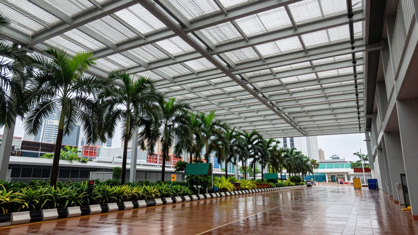
Long-span roofs and canopies in Singapore demand more than a strength check. Their design must respond to wind, intense rainfall, humidity, fire safety, drainage, construction sequencing, and long-term access.
- Establish the roof’s function, geometry, exposure, working life, and regulatory basis before analysis.
- Apply SS EN 1991-1-4 using appropriate wind velocity, terrain, pressure, edge-zone, uplift, and torsion assumptions.
- Treat rainwater, ponding, humidity, lightning, maintenance access, and temporary weather conditions as structural design matters.
- Select a roof system that balances span efficiency, deflection control, support movement, fabrication, and inspection access.
- Verify connections, temporary stability, corrosion protection, fire requirements, tolerances, and post-storm maintenance procedures.
1. Establish the design basis for Singapore projects
A long-span roof or canopy usually has a simple visual brief but a demanding engineering model. Its geometry may be open, lightly clad, exposed on several sides, or connected to a building that moves differently from the canopy. The design basis should therefore be agreed before member sizes are selected. In Singapore, the tropical environment and dense urban setting make early coordination particularly valuable.
Define the roof function, span, height, and exposure category
Begin by recording what the roof must do, rather than describing it only by its appearance. A transit shelter, stadium roof, solar carport, entrance canopy, and industrial roof will have different occupancy, drainage, access, cladding, and service requirements. Establish the clear span, support spacing, overall height, roof pitch, plan dimensions, edge conditions, and whether the structure is enclosed or open-sided.
Exposure is equally significant. A roof over a sheltered courtyard does not experience the same flow pattern as a freestanding canopy beside the coast or above a tall building. Note nearby towers, parapets, trees, cranes, signs, and future development assumptions. These observations influence wind coefficients, local turbulence, maintenance arrangements, and the risk of debris impact.
Identify applicable Singapore regulations and structural standards
The design team should create a compliance register that distinguishes statutory requirements from structural design standards and project specifications. BCA, URA, SCDF, PUB, and other authorities may affect the architectural and technical solution, while the structural engineer must identify the applicable Singapore Standards, Eurocodes, National Annex provisions, material standards, and temporary works requirements.
For wind design, the governing reference in this article is SS EN 1991-1-4. The source material also identifies SS EN 1991-1-6:2005 for actions during execution and BS 5975:2019 for temporary works procedures. A useful Singapore National Annex implementation can help clarify how the Singapore wind provisions are incorporated into a design workflow, but it does not replace review of the current project requirements and authoritative standards.
Set design working life, consequence class, and reliability targets
Working life should reflect the intended use, replacement strategy, and exposure of the roof. A temporary construction canopy, a permanent public entrance, and a solar carport may require different inspection, durability, and reliability decisions. The consequence of failure also depends on what lies below: a lightly occupied service yard is not equivalent to a crowded public concourse.
Agree reliability targets, combination rules, deflection limits, vibration criteria, and assumptions about future alterations in the design brief. These decisions should be traceable in the calculations. Clear assumptions reduce redesign when architectural, authority, or contractor comments arrive later.
Coordinate architectural, fire safety, MEP, and maintenance requirements
A truss becomes difficult to build when services, lighting, sprinklers, gutters, access equipment, and fire protection are left until the end. Reserve service zones and inspection routes during concept design. Coordinate drainage outlets with structural members, and avoid placing access hatches or heavy equipment where they create unexpected local forces.
BIM can support clash detection, quantity take-offs, and construction sequencing, while technical specifications should state material, workmanship, testing, inspection, warranty, and maintenance requirements. The model is useful only when its geometry and ownership are controlled; it should not be treated as a substitute for engineering judgement.
A design-basis schedule is a practical way to keep the disciplines aligned:
| Design input | Why it matters | Typical project decision |
|---|---|---|
| Roof use and occupancy | Establishes imposed and access actions | Public, service, parking, or industrial use |
| Geometry and exposure | Influences wind flow and load paths | Freestanding, attached, sheltered, or coastal |
| Durability environment | Determines protection and inspection | Coated steel, galvanized steel, or aluminum |
| Fire and services strategy | Controls interfaces and clearances | Fire resistance, lighting, drainage, and MEP zones |
The schedule should be signed off before detailed analysis begins. It provides a common reference when a later change to span, cladding, support, or use affects the structure.
2. Determine wind actions using SS EN 1991-1-4
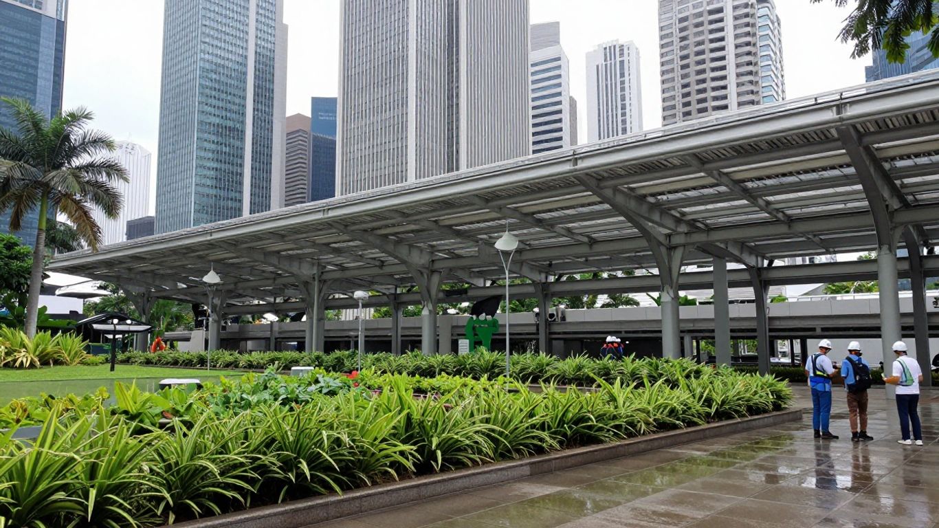
Wind is often the governing action for a long-span canopy because the structure is light, flexible, and exposed to suction from several directions. SS EN 1991-1-4 provides the framework for determining characteristic wind actions on the whole structure, components, and attached elements. The engineer must still make location-specific decisions about terrain, geometry, internal pressure, local zones, and the Singapore National Annex.
Establish the basic wind velocity and directional factors
Start with the fundamental basic wind velocity and apply the relevant directional, season, and other factors required by the adopted provisions. Basic velocity pressure varies with the square of wind velocity, so an apparently modest change in the input can materially affect design actions. Record the source, reference period, air density, and National Annex assumptions in the calculation package.
A worked Eurocode wind calculation is useful for understanding the sequence from basic velocity to velocity pressure and peak pressure. It is an illustrative technical reference, however; a Singapore project requires the applicable Singapore data and assumptions rather than figures copied from another country.
Account for terrain, building height, and surrounding obstructions
Terrain roughness changes the mean wind profile and turbulence with height. Classify the actual surroundings rather than relying on a generic urban label. Open waterfronts, low-rise districts, dense high-rise areas, and partially developed sites can produce different flow conditions, especially around roof edges and corners.
Consider the height of the roof above ground, the height of the supporting building, displacement caused by nearby structures, and possible shielding or channeling. Obstructions should not be assumed to reduce load without a defensible basis. In some arrangements they increase turbulence or create concentrated suction at the canopy edge.
Evaluate external and internal pressure coefficients
External pressure coefficients depend on roof shape, slope, wind direction, loaded area, and location within the roof plan. A canopy with a raised edge, curved profile, or discontinuous covering may not fit a simple enclosed-building model. Internal pressure is also relevant where the roof forms part of a building envelope or where openings allow pressure to develop beneath the roof.
Separate global frame actions from local cladding and fixing actions. The pressure applied to a purlin or panel fixing may be substantially different from an averaged pressure used for the main truss. Keep signs and load directions explicit so that suction and downward pressure are not accidentally combined or omitted.
Check global wind effects, local cladding pressures, and edge zones
The global model should capture overall uplift, lateral shear, overturning, torsion, diaphragm action, and load distribution between supports. Local checks should cover sheeting, purlins, rails, edge members, bolts, clips, and their supporting plates. Edge and corner zones commonly require particular attention because flow separates around discontinuities.
Use a load map that shows where each coefficient applies and how the pressure reaches the primary structure. Online Eurocode calculation tools may assist with preliminary checking, but final design remains dependent on the selected code edition, National Annex, geometry, and engineering review.
Consider uplift, torsion, and wind-sensitive canopy configurations
Uplift can reverse the expected force in hold-down bolts, bearings, brackets, columns, and foundations. A wide canopy may also experience torsion when pressure is uneven across its plan, while a cantilevered or asymmetrical roof can develop significant twisting at its support line. These effects should be checked with realistic load arrangements, not only a uniform pressure case.
For unusually flexible, irregular, or wind-sensitive forms, consider refined computational modelling, physical testing, or specialist wind assessment. The current standard framework includes provisions for ordinary land-based structures, while unusual cases may require a more tailored technical justification. The result should clearly state the limits of the adopted model and any sensitivity checks performed.
3. Account for tropical rain and environmental actions
Singapore’s rainfall is not merely a waterproofing concern. Water can add significant temporary weight, trigger ponding instability, obstruct access, and accelerate deterioration at poorly detailed interfaces. A long-span roof should be designed as a coordinated structural and drainage system, with overflow paths that remain credible when primary outlets are blocked.
Design roof slopes, gutters, outlets, and overflow paths
Set sufficient falls toward gutters and outlets while allowing for fabrication tolerances and structural deflection. Gutters need support against full water loads, and outlets should be positioned so that a local sag does not create a low point that is invisible during inspection. Overflow routes should discharge safely without directing water onto electrical equipment, public paths, or sensitive building interfaces.
Coordinate downpipes, scuppers, gutters, and access points with the truss layout. A drainage line that passes through a bracing node may be difficult to inspect and may encourage unplanned cutting on site. The structural drawings should identify loads from full gutters and any concentrated support reactions.
Check ponding and water accumulation on low-slope roofs
Low-slope roofs are vulnerable to a feedback cycle: water increases load, deflection increases, and the resulting depression collects more water. Check the roof’s stiffness, drainage capacity, support spacing, and construction tolerances together. Do not rely on nominal slope alone if the predicted serviceability movement can cancel it.
The assessment should include blocked-outlet or localized accumulation scenarios where appropriate. Temporary conditions, incomplete roof coverings, and construction debris can be more severe than the final drainage arrangement. Where ponding is credible, provide positive drainage, overflow relief, or sufficient stiffness and strength against the resulting action.
Combine permanent, imposed, wind, and rain actions appropriately
Load combinations should distinguish permanent roof weight, cladding, services, maintenance actions, rainwater, wind pressure, and uplift. The governing combination for a main truss may differ from that for a gutter, purlin, connection, or support bracket. Carefully define whether rainwater is included as an imposed action, an accidental blockage scenario, or another project-specific case under the adopted design basis.
A compact action register helps prevent omissions:
- Permanent weight of trusses, purlins, roofing, gutters, and fixed services.
- Maintenance personnel, access equipment, replacement panels, and temporary stored materials.
- Wind pressure, suction, lateral force, torsion, and uplift on exposed surfaces.
- Rainwater accumulation, blocked outlets, full gutters, and overflow discharge effects.
After establishing the combinations, compare their effects at member, connection, support, and foundation level. A single “worst case” envelope can hide which action governs and may lead to poor detailing if the load path is not understood.
Consider lightning, humidity, temperature, and maintenance access loads
Lightning protection should be coordinated with the roof’s electrical and earthing design. Down conductors need low-impedance paths with sensible routing, minimal sharp bends, and suitable separation from occupants and sensitive equipment. Structural steel may form part of a coordinated system only when continuity, joints, coatings, and earthing assumptions have been deliberately verified.
Humidity affects coating durability, fasteners, concealed surfaces, and drainage interfaces. Temperature movement can be significant across a long roof, particularly where dark cladding or solar panels are installed. Include maintenance loads at locations where workers will actually stand, and provide safe routes that do not depend on fragile roof sheets.
Assess whether seasonal storms or temporary conditions require additional checks
Singapore does not experience the same typhoon regime as some neighboring regions, but severe thunderstorms, gust fronts, intense rainfall, and construction-stage exposure still deserve attention. Temporary roofs, partially clad frames, lifted modules, and incomplete bracing can have a different aerodynamic response from the completed structure.
Review the expected exposure period, weather limitations, emergency securing arrangements, and contractor method statement. If a temporary condition is more critical than the permanent configuration, it should be identified as a design situation rather than left to site judgement.
4. Select and configure the long-span truss or canopy system
System selection sets the pattern for every later decision: fabrication, transportation, erection, drainage, movement, and maintenance. Steel trusses may offer familiar fabrication and efficient depth, while space frames distribute loads in two directions. Portals, arches, and cable-supported systems can suit particular architectural forms but introduce different stability and detailing demands.
Compare steel trusses, space frames, portal systems, and cable-supported options
Compare alternatives against the real project constraints rather than span alone. A planar truss can be efficient where supports are aligned and services can pass below it. A space frame may distribute irregular loads and provide multiple load paths, but its nodes and access requirements can be more involved. Portal systems may simplify repetitive bays, while cable-supported roofs require careful pretensioning, anchorage, and erection control.
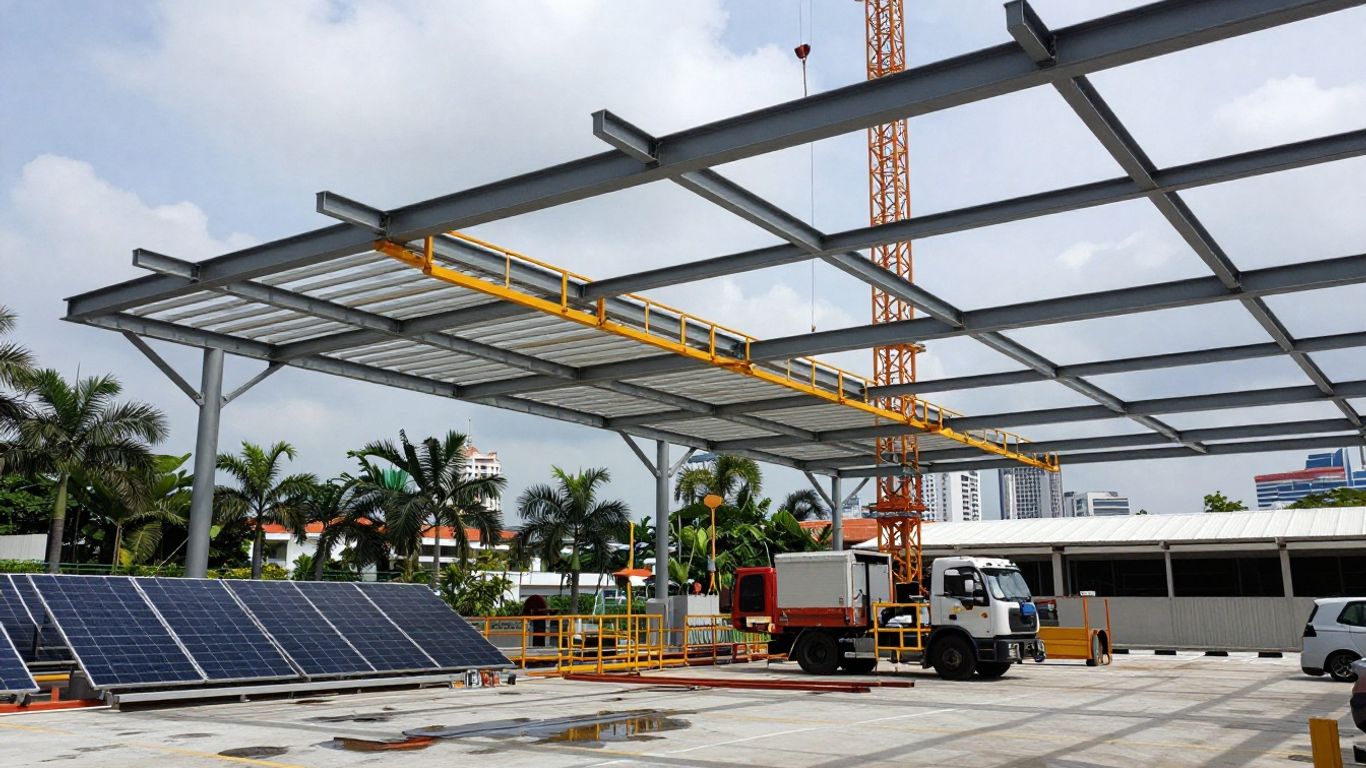
For elevated solar installations, the service context may favor a raised canopy or specially designed framework that accommodates panels and shaded parking. The documented elevated solar structures service should only be considered where its actual project scope and engineering deliverables have been confirmed; the structural concept still needs project-specific analysis and approval.
Set span-to-depth ratios and preliminary member arrangements
Choose a preliminary depth that limits axial forces, deflection, fabrication complexity, and architectural impact. Very shallow trusses may look clean but generate high chord forces and sensitive deflection behavior. Excessive depth can obstruct lighting, services, sightlines, or fire separation zones.
Arrange top and bottom chords, diagonals, verticals, purlins, and lateral restraints so that load paths remain legible. Node spacing should reflect available rolled sections, connection access, cladding modules, transport limits, and the position of concentrated loads. Early member arrangement is also the right time to consider how the frame will be lifted.
Control deflection, vibration, and visual movement requirements
Strength is only one part of a successful canopy. Excessive deflection can reverse drainage falls, damage cladding, misalign gutters, or create a visibly wavering roof. Vibration may arise from walking, equipment, wind, rain impact, or flexible suspended elements, particularly where the public is close to the structure.
Set serviceability criteria with the architect, façade or roofing supplier, MEP team, and operator. Review both calculated movement and differential movement between adjacent components. If the roof is visually prominent, a stricter movement target may be appropriate even when the code strength checks are satisfied.
Resolve support conditions, expansion joints, and interfaces with existing structures
Decide early which supports are pinned, guided, sliding, or moment-resisting, and ensure the analysis matches the physical detail. Long roofs may need movement joints or bearings to accommodate temperature change, shrinkage, settlement, and building drift. A connection to an existing structure should be based on verified information about its reinforcement, capacity, condition, and movement history.
Avoid forcing a new canopy to follow an existing building’s movement unless that compatibility has been demonstrated. Survey information, opening-up works, and a strength evaluation may be necessary before fixing brackets or base plates to an existing element.
Plan access for inspection, cleaning, lighting, and building services
Access should be designed into the structural grid. Provide walkways, anchor points, removable panels, lighting supports, and safe routes to gutters and outlets. Allow for replacement of panels, fixtures, bolts, seals, and drainage components without requiring uncontrolled loading on the roof.
The arrangement should also preserve access to critical connections and concealed steelwork. A visually minimal canopy can become expensive to maintain when every inspection requires specialist access equipment or temporary removal of cladding.
5. Design members, connections, and support zones
Once the system and actions are established, the design must follow the complete load path from roof covering to foundation. Long-span trusses often contain slender compression members, reversal-prone diagonals, and highly loaded nodes. Support zones deserve particular scrutiny because reactions may include uplift, horizontal force, torsion, and movement restraint.
Check compression members for buckling and second-order effects
Compression chords, struts, and diagonals should be checked for flexural, torsional, and local buckling using effective lengths consistent with the actual restraint system. A member that appears braced in elevation may be poorly restrained out of plane if purlins, sway bracing, or connections are flexible. Model imperfections and eccentricities where they materially influence capacity.
Second-order effects can amplify moments in slender members and frames. Review the stability coefficient, sway behavior, joint stiffness, and construction tolerances. For aluminum alternatives, lower elastic modulus and heat-affected zones near welded connections may require specialized analysis and careful interpretation of Eurocode 9 provisions.
Design tension members, chords, diagonals, and restraint systems
Tension elements require checks for gross-section yielding, net-section fracture, block tearing, connection resistance, and fatigue where cyclic actions are relevant. Wind reversal means that a diagonal designed primarily in tension may enter compression under another direction. Restraint systems should therefore be checked for both force direction and installation sequence.
Chord splices, tie rods, bracing members, and anti-sway systems should have enough stiffness to control geometry as well as enough strength to resist the design action. Make the intended force path clear on drawings so that temporary and permanent restraints are not confused.
Detail bolted and welded connections for strength and constructability
Connection design should account for bolt group eccentricity, bearing, slip, weld access, local plate bending, prying, block tearing, and corrosion protection. Shop welds may be preferable for accuracy, while site bolting can reduce weather-sensitive work and simplify inspection. The choice depends on transport, crane reach, tolerances, fire protection, and the contractor’s capabilities.
Avoid congested nodes where every diagonal terminates on a small plate with no room for tools or inspection. Provide sensible erection gaps, bolt access, drainage paths, and touch-up zones. Connection forces should be taken from the relevant combinations rather than a convenient but non-governing envelope.
Verify column, bracket, base plate, and foundation load transfer
Support reactions should be transferred through a defined sequence of plates, stiffeners, bolts, welds, brackets, columns, and foundations. Check local web crippling, flange bending, concrete breakout, anchor tension, shear, overturning, bearing, sliding, and foundation eccentricity. Uplift can govern even when vertical gravity reactions are modest.
Where the canopy is supported on an existing building, verify the supporting member and its surrounding structure. A bracket may be adequate in isolation but unacceptable when it introduces torsion or concentrated force into a thin slab edge, façade beam, or lightly reinforced wall.
Address differential movement between the canopy and supporting building
Movement compatibility should include thermal expansion, settlement, imposed deformation, wind drift, and construction tolerances. Sliding bearings, slotted holes, flexible seals, and movement joints can accommodate relative displacement, but each device must be detailed so that it does not accidentally restrain the movement it is meant to permit.
State movement directions, limits, inspection needs, and replacement provisions. Interfaces that are left vague often transfer unintended force into cladding or waterproofing, creating problems that appear architectural but originate in structural restraint.
6. Protect the structure against corrosion, fire, and water ingress
Singapore’s warm, humid environment makes durability a design decision from the first sketch. Water traps, unsealed hollow sections, damaged coatings, and inaccessible fasteners can shorten service life even when the primary steel is adequately sized. Protection should be coordinated with fabrication, transport, erection, fire engineering, drainage, and inspection.
Select steel grades, coatings, galvanizing, and corrosion allowances
Choose steel grade and protection system according to exposure, access, expected working life, fabrication method, and maintenance plan. Coatings need compatible surface preparation, specified dry-film thickness, repair procedures, and clear responsibility for site touch-up. Galvanizing may suit smaller components or repetitive elements, but member dimensions, venting, drainage, distortion, transport, and connection details must be checked.
Corrosion allowances should not be used to excuse poor detailing. Hollow sections require sealed or deliberately drained ends, and dissimilar metals need appropriate separation. Where aluminum is selected for a lightweight canopy, its lower stiffness and welded heat-affected zones must be considered alongside its corrosion resistance.
Detail drainage, sealed joints, and interfaces to prevent trapped moisture
Every plate, stiffener, gusset, splice, and hollow section should be reviewed for water retention. Provide falls, drain holes, vent holes, sealed overlaps, and accessible inspection points where needed. Sealants should be selected for movement and exposure, with substrate preparation and replacement intervals included in the specification.
Interfaces between roof sheets, gutters, façade elements, brackets, and existing construction are common leakage points. Keep drainage paths independent of critical structural cavities where possible. If water reaches a connection, it should be able to leave rather than remain concealed around bolts or welds.
Specify inspection and maintenance provisions for Singapore’s humidity
A maintenance plan should identify what is inspected, how often, by whom, and under what access arrangement. It should cover coating breakdown, rust staining, blocked outlets, failed sealants, loose fasteners, bearing movement, cracking, deformation, and damage from maintenance equipment. Photographic records and marked-up inspection drawings can make trends easier to detect.
Specify wash-down or cleaning requirements where deposits may collect, especially near roadways, carparks, coastlines, or mechanical discharge points. Maintenance access should be safe and repeatable, not dependent on improvised ladders or fragile roof panels.
Coordinate fire resistance, compartmentation, and non-combustible material requirements
Fire strategy affects member protection, compartment lines, penetrations, roof build-up, insulation, and service supports. Confirm whether the canopy is within a building fire compartment, forms part of an escape route, or requires a particular fire resistance period. Coordinate the structural solution with SCDF requirements and the project fire engineer.
Do not assume that an exposed canopy is outside all fire considerations. Solar panels, membranes, insulation, suspended ceilings, lighting, and service penetrations may introduce additional requirements. The final specification should identify protection thickness, fixing methods, inspection, and repair responsibilities.
Protect cut edges, welds, fasteners, and concealed steelwork
Protection often fails first at site-cut edges, welds, bolt heads, damaged lifting points, and connection interfaces. Define acceptable preparation and repair systems before erection begins. Welded areas may need cleaning, testing, stripe coating, and an agreed sequence that avoids sealing contamination into the system.
Concealed steelwork deserves the same attention as exposed members. If inspection will be impossible after cladding, document the installation checks and provide a durable detail rather than relying on future access that may never occur.
7. Verify constructability, temporary stability, and long-term performance
A completed analysis does not guarantee a safe erection. Long-span members are vulnerable while being lifted, supported at temporary points, connected in partial frames, or exposed without their final bracing and cladding. Construction engineering should be integrated with permanent design so that the structure remains stable at every meaningful stage.
Plan lifting, transportation, erection sequence, and temporary bracing
Break the roof into transportable modules and identify lifting points, pick-up forces, temporary plates, and allowable distortion. Review crane capacity, radius, site access, wind limits, storage supports, and the sequence for closing bracing and installing purlins. A module that is stable in its final position may be unstable during a single pick.
Temporary bracing should have a defined purpose, capacity, connection detail, installation sequence, and removal trigger. The contractor’s method statement must align with the engineer’s assumptions, particularly where stability depends on partially completed diaphragms or roof sheeting.
Check construction-stage wind actions under SS EN 1991-1-6
Construction-stage wind actions should be assessed under SS EN 1991-1-6:2005 using the exposure duration, partial geometry, temporary supports, and anticipated weather limitations. Open frames, lifted trusses, incomplete cladding, and temporary roofs can have different pressure distributions from the finished structure.
The temporary works design should state hold points, maximum permitted wind conditions, emergency securing measures, and who has authority to stop work. For broader temporary works support, temporary works design guidance can be relevant, provided the linked scope is verified against the actual project and local requirements.
Define survey, connection inspection, and tolerance-control procedures
Survey the supports before erection and check levels, offsets, anchor positions, bearing locations, and interface geometry. Establish tolerances for member straightness, node position, splice alignment, bolt holes, bearing seats, and drainage falls. Tolerances should be realistic for fabrication and erection, while still protecting structural performance.
Inspection should cover bolt grade and tightening, weld quality, coating preparation, concealed drainage, bearing installation, and completion of temporary bracing. Nonconformances need a controlled engineering disposition rather than informal site adjustment.
Use staged analysis, physical testing, or computational models where appropriate
Staged analysis is valuable when stiffness, restraint, load distribution, or support conditions change during erection. Computational models should reflect actual releases, temporary restraints, connection stiffness, imperfections, and the timing of cladding or ballast installation. Results should be checked against simple equilibrium and hand calculations so that modelling errors do not become design assumptions.
Physical testing or specialist numerical work may be appropriate for unusual nodes, flexible roofs, complex wind-sensitive forms, or proprietary components. The purpose should be clearly defined: validating strength, movement, vibration, pressure distribution, or constructability.
Prepare inspection, maintenance, and post-storm assessment requirements
The handover package should include drawings, material certificates, coating records, inspection reports, as-built surveys, drainage information, fire protection records, and movement limits. Operators need clear instructions for routine cleaning, access, fastener checks, gutter clearing, and coating repairs.
After an intense storm, inspect for uplift damage, displaced panels, loose fixings, distorted members, blocked outlets, water ingress, and movement at bearings or joints. If damage is found, isolate affected areas and obtain an engineering assessment before returning the canopy to normal use. Long-term performance is preserved through planned observation, not through the original calculation alone.
Conclusion
A Singapore long-span roof or canopy succeeds when its structural concept, wind assessment, tropical drainage, durability strategy, fire coordination, and construction sequence are developed as one system. SS EN 1991-1-4 is central to wind design, but reliable performance also depends on explicit assumptions, realistic interfaces, careful detailing, and disciplined inspection after handover.
Frequently Asked Questions
What makes long-span canopies challenging in Singapore?
They are often lightweight and flexible while being exposed to strong local suction, intense rainfall, humidity, maintenance actions, and complex interfaces with buildings, services, and public areas.
Is SS EN 1991-1-4 sufficient for the entire canopy design?
No. It addresses wind actions, but the project also requires design for gravity, rainwater, temperature, fire, durability, construction stages, materials, connections, foundations, and applicable local regulations.
How should uplift be considered for a canopy?
Uplift should be traced through cladding, purlins, trusses, bearings, bolts, brackets, columns, and foundations. Reversal, torsion, uneven pressure, and local edge effects should be included where relevant.
Why is ponding a structural concern?
Accumulated water adds load and can increase deflection. The resulting depression may collect more water, creating a feedback cycle that affects strength, drainage, cladding, and serviceability.
When might wind tunnel testing or advanced modelling be needed?
It may be appropriate for unusually flexible, irregular, large, exposed, or wind-sensitive roofs where simplified code coefficients do not adequately describe the aerodynamic behavior.
What should be checked during erection?
The team should verify lifting points, temporary bracing, support geometry, weather limits, partial-frame stability, connection installation, tolerances, and the sequence for completing permanent restraints.
How can the service life of a tropical steel canopy be improved?
Use suitable protection systems, eliminate water traps, seal or drain hollow sections, protect cut edges and welds, provide inspection access, maintain drainage, and record recurring defects through planned inspections.