

Key Takeaways
Connection rigidity is a modeling choice that can materially change stiffness, force distribution, and predicted failure behavior. A defensible FEA model connects that choice to the real joint, the design standard, and the evidence available for validation.
- Pinned, rigid, and semi-rigid idealizations describe different moment–rotation behaviors.
- Rotational stiffness affects frame drift, member moments, reactions, and load sharing.
- Simple shear joints may be idealized as pinned, while moment connections often need rigid or semi-rigid treatment.
- Nonlinear models should account for slip, contact, yielding, bearing, prying, and local failure where relevant.
- Sensitivity studies and clear documentation are essential when joint stiffness influences design decisions.
Understand connection rigidity and its effect on structural behavior
A steel connection is not merely a point where two members meet. Its deformation can alter the way a frame carries gravity, wind, seismic, and construction loads. In FEA, the selected joint idealization therefore needs to reflect both the physical detailing and the level of certainty required by the design.
What pinned, rigid, and semi-rigid connections represent
A pinned connection transfers forces but is assumed to provide negligible moment resistance, allowing relative rotation between connected members. A rigid connection maintains nearly the same rotation on either side of the joint and transfers significant moment. A semi-rigid connection lies between these limits, with a finite rotational stiffness that changes as the connection loads, slips, yields, or develops contact.
The labels are idealizations, not descriptions of every physical detail. A bolted joint may have meaningful initial rotational stiffness, and a welded joint may still experience flexibility through plates, bolts, weld zones, or the adjoining members.
How rotational stiffness changes force distribution
Rotational stiffness influences whether bending is concentrated in the beam, shared with the joint, or redistributed through the frame. A stiffer joint can reduce local beam rotation but increase connection moment and column or panel-zone demand. A flexible joint may reduce the moment delivered to the connection while increasing drift and secondary effects elsewhere.
This interaction is especially relevant in continuous frames. The same applied load can produce different support reactions and member envelopes when the joint stiffness changes, even if the member geometry and material properties remain unchanged. Joint stiffness affects the whole load path, not only the immediate connection detail.
The relationship between moment–rotation behavior and joint classification
The most useful description of a connection is often its moment–rotation curve. The initial slope gives an elastic rotational stiffness, while the curve’s shape reveals slip, yielding, stiffness degradation, pinching, hardening, and eventual loss of resistance. Classification should be based on the connection’s position within the structural system and the relevant stiffness and strength criteria, rather than on the connection name alone.
For a linear preliminary model, one secant or tangent stiffness may be sufficient. For a performance assessment, however, the complete curve or a suitable multilinear approximation may be needed. The chosen curve should be consistent with the loading direction, load history, temperature, fabrication condition, and expected failure mode.
When connection assumptions control design results
The assumption becomes critical when joint flexibility is comparable with member flexibility, when frame drift is a governing limit state, or when connection forces are close to their resistance. It also matters in irregular structures, long-span frames, heavily loaded transfer levels, and systems where second-order effects amplify displacement.
A useful first check is to run bounding models: one with idealized pinned joints and another with rigid joints. If the resulting forces, drifts, or reactions differ materially, the design should not rely on an undocumented intermediate assumption. That difference is evidence that a semi-rigid model or a more detailed joint study is warranted.
Choose the appropriate connection idealization
Connection idealization should begin with the structural role of the joint, not with the element type available in the software. Drawings, connection calculations, erection requirements, and the governing code all provide clues about the intended force transfer. The model should be no more detailed than necessary, but it must capture the behavior that controls the engineering decision.
A clear distinction between global and local models helps. The global model may use springs or releases to capture frame behavior, while a local connection model can resolve bolts, plates, welds, and contact surfaces. This multi-level approach is often more efficient than modeling every connection in full detail.
Modeling simple shear connections as pinned
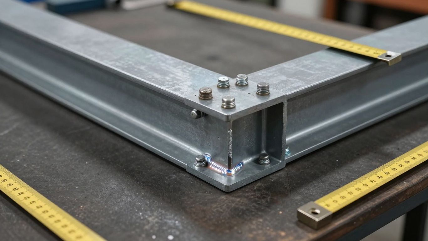
Simple shear connections are commonly idealized as moment-released where their intended function is to transfer vertical or horizontal shear with limited rotational restraint. The release should be applied at the correct member end and coordinate system, while axial restraint is retained or released according to the actual connection and surrounding framing.
The pinned assumption should still be checked against detailing. Plate thickness, bolt group arrangement, eccentricity, continuity plates, and beam end restraint can provide more rotational resistance than a purely conceptual diagram suggests. For sensitive frames, a small rotational stiffness may be more realistic than an absolute zero.
Representing moment-resisting connections as rigid
Moment-resisting joints may be modeled as rigid when the connection and nearby members are intended to maintain compatible rotations and their flexibility is small relative to the frame response. This is a practical global idealization, but it does not prove that the physical connection has infinite stiffness or unlimited strength.
Rigid behavior must be accompanied by appropriate checks for bolt tension, weld resistance, plate bending, panel-zone shear, local buckling, and ductility. A rigid link that bypasses these mechanisms can produce a structurally neat model with an unrealistic force path.
Identifying cases that require semi-rigid behavior
Semi-rigid behavior deserves attention when a joint has a discernible elastic rotation, when slip affects serviceability, or when connection deformation contributes substantially to storey drift. End-plate connections, flexible flange plates, partial-strength joints, and certain braced-frame details commonly require this consideration.
The need is also signaled by conflicting results from pinned and rigid models. Where the classification changes member sizing, vibration response, stability, or connection demand, use a stiffness derived from calculations, testing, or a calibrated local model rather than choosing the convenient limit.
Considering axial, shear, and rotational degrees of freedom
Rotation about the intended bending axis is only one possible degree of freedom. A connection may restrain axial separation, permit shear slip, resist torsion, or open under load. Each of these behaviors should be considered in the local coordinate system used by the FEA model.
Before assigning releases or connectors, identify the six relative degrees of freedom and decide whether each is fixed, released, elastic, frictional, or contact-dependent. This simple inventory prevents a model from accidentally releasing axial load or restraining a translation that the physical joint cannot carry.
Define connection properties for FEA models
Once the idealization is selected, the analyst must assign properties that are traceable to geometry, materials, detailing, and test evidence. A spring constant without a stated derivation is difficult to review and easy to misuse. The property should also state whether it is initial, tangent, secant, positive-direction, negative-direction, or unloading stiffness.
Connection properties may be linear for a serviceability study or nonlinear for strength and progressive-response work. The appropriate choice depends on the question being asked. A global model intended to estimate drift may need a reliable initial stiffness, while a failure assessment requires resistance and post-yield behavior as well.
Estimating rotational stiffness from connection geometry
Rotational stiffness can be estimated by relating connection moment to the deformation of its components. Plate bending, bolt elongation, weld deformation, shear distortion, and local member flexibility each contribute compliance. A simple component arrangement can provide a useful first estimate, provided the deformation mechanisms are not counted twice.
Geometry has a strong influence. Longer lever arms can increase moment resistance, while thin plates, flexible end plates, large bolt clearances, and eccentric load paths can reduce initial stiffness. The estimate should be evaluated over the load range relevant to the global analysis rather than treated as a universal constant.
Using component-based methods for bolts, welds, plates, and end plates
A component-based approach separates the connection into springs or resistance components and combines them through the actual force path. Bolts may contribute tension, shear, and slip resistance; welds transfer force through their effective throat and layout; plates deform in bending, yielding, or bearing; and end plates couple bolt forces with prying action.
The method is most reliable when the assumed components match the physical detail. For example, a connection with flexible column flanges should not be reduced to a bolt spring alone. Local checks should also consider eccentricity, shear lag, edge distances, weld access, and the interaction between components.
Applying nonlinear material and contact behavior
Nonlinear material laws allow plates, bolts, weld regions, and adjoining members to yield when their stress and strain histories require it. Contact formulations can distinguish compression bearing from separation, while friction models can capture resistance before or after slip when suitable data are available.
The analyst should define yield criteria, hardening, damage or fracture limits, and unloading behavior deliberately. Excessive material idealization can mask local failure, whereas an overly elaborate law can create convergence problems without improving the decision being made.
Representing slip, gap opening, bearing, and prying effects
Slip changes the early response of many bolted connections and may create a noticeable transition in the moment–rotation curve. Gap opening changes the active contact area and can move force into bolts, welds, or compression zones. Bearing and prying introduce local deformation and often increase demand in components that a rigid link would bypass.
These effects can be represented with contact pairs, nonlinear springs, connector elements, or detailed solid and shell assemblies. Select the simplest representation that reproduces the relevant mechanism, then confirm it with equilibrium checks and local deformation plots.
Implement pinned, rigid, and semi-rigid joints in FEA software
Implementation is where a sound engineering idealization can be lost through an incorrect constraint, orientation, or element connection. Every release and connector should be checked against the physical joint and the model’s nodal topology. The analytical representation also needs to remain compatible with the intended code checks and design envelopes.
A global frame model commonly uses beam members with releases, springs, or multipoint constraints. A local model may use shells or solids around the joint and beams for the incoming members. The transition between these scales requires care so that offsets, rigid zones, and local stiffness are not accidentally duplicated.
Using releases and boundary conditions for pinned behavior
Member-end releases are a direct way to remove selected force or moment components from a beam element. They should be assigned at the connection face or analytical end that corresponds to the real detail, not automatically at every intersection. End offsets may be needed when the physical joint center and member reference line do not coincide.
After applying a release, inspect reactions and internal forces. A nominally pinned joint should not develop a significant released moment because of an unintended constraint, duplicate node, or incompatible element connection. The released degree of freedom should also be checked in the correct local axis.
Applying multipoint constraints and rigid links
Multipoint constraints tie the motion of several nodes to a master node or reference surface. Rigid links are useful for short zones where deformation is negligible, such as a connection between a beam centerline and a column flange reference point. They can also transfer offsets cleanly in a reduced-order global model.
Their scope should stop where real flexibility begins. If a rigid region spans a flexible plate or panel zone, it suppresses the deformation that the analysis is meant to predict. Review constraint equations, not just the rendered geometry, and check whether the link introduces duplicate restraints.
Assigning rotational springs and connector elements
A rotational spring provides a compact semi-rigid representation when the moment–rotation relation is known or can be estimated. Connector elements can extend this idea to axial, shear, torsional, frictional, and gap behavior. Define positive and negative directions consistently, especially where the joint is asymmetric.
For nonlinear connectors, use a curve with clearly identified initial stiffness, transition points, resistance, and unloading rules. Verify the response with a simple single-joint test model before placing the connector in the complete frame. This isolates property errors from global instability.
Selecting beam, shell, and solid elements around the joint
Beam elements are efficient for global force distribution but cannot resolve bolt holes, plate yielding, weld geometry, or contact pressure directly. Shell elements provide a practical middle ground for plates and webs, while solid elements are suited to detailed three-dimensional stress states and complex contact regions.
Element choice should follow the failure mode and required output. A shell model needs suitable thickness, connectivity, offsets, and mesh refinement around bolt lines and weld terminations. A solid model needs compatible interfaces, realistic contact, and enough refinement to avoid interpreting numerical peaks as physical fracture.
Calibrate and validate connection rigidity
Calibration gives the model a defensible relationship with observed or independently calculated behavior. Validation is broader: it asks whether the model predicts the response relevant to the engineering purpose. Neither process is satisfied by obtaining a smooth contour plot.
Use a hierarchy of evidence. Start with equilibrium and hand calculations, compare stiffness and resistance with recognized design procedures, and then use experimental data or a detailed local model where uncertainty remains significant. The final comparison should discuss both agreement and the reasons for any difference.

Interpreting experimental moment–rotation data
Experimental curves often include seating, bolt slip, local yielding, unloading, and irreversible deformation. The initial few points may not define the structural stiffness, and repeated cycles may produce a different response from monotonic loading. Identify the portion of the curve that corresponds to the design load range and intended loading protocol.
Record how the test defines rotation, where displacement instruments are located, and whether member deformation has been removed. Comparing a connection-only curve with a frame-level FEA rotation without matching those definitions can create an apparent error that is really a measurement mismatch.
Using design standards and component-method calculations
Design standards provide classification rules, component resistances, detailing limits, and accepted calculation procedures. The applicable standard depends on the project jurisdiction and material system; projects reviewed in Singapore may require alignment with Singapore Standards and adopted Eurocode provisions, while international work may involve BS, ACI, or other specified requirements.
Component calculations are valuable even when a detailed FEA model is available. They provide independent estimates of stiffness, strength, and governing mechanisms. For steel connection verification, the review should cover force transfer, stiffness, ductility, eccentricity, prying action, shear lag, edge distances, and weld access where relevant.
Conducting mesh sensitivity and numerical convergence checks
A mesh refinement study should focus on outputs that inform the decision: joint rotation, connection moment, bolt force, plate yield extent, contact pressure, or drift. Refining the entire structure uniformly is rarely necessary. Instead, refine the connection region and compare results until the selected outputs stabilize within an engineering tolerance.
Convergence also depends on load stepping, contact stabilization, material regularization, and constraint formulation. A converged solution is not automatically accurate, but a result that changes materially with mesh or step size should not be treated as final.
Comparing FEA predictions with hand calculations and test results
Comparison should be made at several levels: global equilibrium, elastic stiffness, peak resistance, deformation pattern, and failure sequence. Hand calculations may capture the governing component while FEA reveals load redistribution around it. Test results may include imperfections and fabrication tolerances absent from the idealized model.
When results disagree, inspect assumptions before changing mesh density. A different bolt preload, friction coefficient, boundary condition, material curve, or definition of rotation may explain more than numerical resolution. Finite Element Analysis basics can help establish the broader distinction between a numerical method and the physical assumptions supplied to it.
Evaluate nonlinear response and design performance
Nonlinear analysis is useful when the connection’s behavior affects strength, ductility, stability, or load redistribution. It should be selected because a linear model cannot answer the design question, not simply because the software offers nonlinear options. The analysis plan should state the expected response and the evidence needed to judge it.
For steel structures, local phenomena can govern before the global frame reaches its nominal capacity. Connection flexibility may interact with P-delta effects, local buckling, residual stress, imperfections, and cyclic degradation. These interactions need a model that is sufficiently detailed but still numerically controllable.
Running geometric and material nonlinear analyses
Geometric nonlinearity accounts for changes in equilibrium caused by displacement, including second-order effects and large rotations where applicable. Material nonlinearity captures yielding, hardening, and unloading. Together they can show how a frame moves from elastic response into redistribution and possible instability.
Introduce nonlinearities progressively during model development. First confirm the elastic model, then activate geometric effects, followed by material, contact, and connector nonlinearities as needed. This sequence makes it easier to identify which feature causes a change in response or a failure to converge.
Assessing stiffness degradation, yielding, and connection failure modes
A realistic nonlinear response may show an initial stiff region, a transition caused by slip or yielding, and a softer post-yield path. Track tangent stiffness, rotation, dissipated energy, and force redistribution rather than relying only on the final load factor. Degradation can be gradual or abrupt, depending on the component and loading history.
The assessment should distinguish connection failure from failure in adjacent members. If the joint softens because a beam hinge forms outside the connection, that is a different design outcome from bolt fracture or end-plate tearing. The model’s output requests should be planned around these distinctions.
Checking local buckling, bolt failure, weld fracture, and plate yielding
Local buckling requires appropriate plate slenderness, imperfections, boundary conditions, and material behavior. Bolt failure may involve tension, shear, combined interaction, slip, bearing, or prying. Weld fracture and plate yielding require attention to effective geometry, stress concentration, ductility, and the limitations of the selected material model.
Peak stresses at sharp corners are not automatically fracture predictions. Use averaged or structural stress measures where appropriate, supplementing them with component resistance checks and observed deformation patterns. A local solid model may clarify a hotspot, but it does not remove the need for engineering interpretation.
Reviewing convergence problems and unrealistic load paths
Nonconvergence can indicate a genuine instability, but it can also result from incompatible constraints, excessive contact stiffness, poor element quality, abrupt material curves, or an unconstrained rigid-body mode. Review the last stable increment, contact status, reaction balance, and deformation field before altering solver controls.
Unrealistic load paths are equally serious when the solution converges. Look for forces bypassing plates through rigid links, tension transmitted across an open gap, or moments appearing in a released member. A visually plausible deformed shape is not enough; equilibrium and connectivity must support the interpretation.
Avoid common connection-modeling errors
Most connection-modeling errors are not caused by advanced mathematics. They arise when a physical detail, analytical idealization, and design check describe different systems. A short model review at the start can prevent substantial rework later.
The review should cover geometry, axes, offsets, releases, constraints, material data, contact, mesh, loading, and output requests. It should also identify which assumptions are conservative, which are approximate, and which require calibration.
Over-constraining joints with rigid links
Rigid links can unintentionally restrain translations and rotations that should remain flexible. Multiple links meeting at the same reference node may create redundant equations or create an artificial rigid zone larger than the real connection. The resulting frame can appear stiffer while shifting demand into adjacent members.
Use the smallest rigid region that transfers the intended motion. A constraint audit, including the list of tied degrees of freedom and the location of master nodes, is often more revealing than a rendered model view.
Treating all bolted connections as perfectly pinned
Bolted connections vary widely in slip resistance, bolt layout, plate flexibility, pretension, clearance, and bearing condition. A pinned idealization may be acceptable for a simple shear connection in a global model, but it should not be applied automatically to a joint whose rotation influences drift or moment redistribution.
At minimum, compare the pinned assumption with a plausible finite stiffness. If the result changes the governing design check, refine the connection representation or justify the simplification with calculations.
Ignoring member and panel-zone flexibility
A connection may be stiff while the beam flange, column flange, web, or panel zone deforms significantly. Omitting these regions can overstate joint stiffness and understate local demand. Conversely, modeling every plate as flexible without compatible member offsets can double-count compliance.
The boundary between connection and member should be explicit. Include panel-zone shear, continuity plates, doubler plates, flange bending, and web flexibility when they participate in the actual force path or influence the governing limit state.
Using nominal stiffness without documenting assumptions
Nominal stiffness is not a self-explanatory property. State its source, units, coordinate direction, load range, temperature if relevant, and whether it is an initial, tangent, or secant value. Record the assumed resistance and the point at which the property changes.
Documentation should also explain why the idealization is suitable for the model’s purpose. A transparent approximation can be reviewed and improved; an undocumented number can quietly become a design fact.
Establish a practical FEA modeling workflow
A practical workflow moves from structural intent to model detail, then from model results back to engineering judgment. It avoids spending local-model effort on a connection that has no influence on the design decision. It also creates a clear record for checking, authority submissions, and future revisions.
The workflow should be aligned with the project’s governing standards and the expected deliverables. For projects requiring professional engineering endorsement, the analytical model, assumptions, calculations, and design conclusions should be sufficiently traceable for independent review.
Define the connection’s role in the global structure
Begin by asking what the connection is expected to do: transfer shear, develop moment, brace a frame, accommodate movement, provide continuity, or resist accidental and cyclic actions. Identify whether stiffness, strength, ductility, fatigue, or serviceability governs the decision.
Map the joint into the global load path before selecting an element formulation. This step clarifies which degrees of freedom matter and prevents a local connection property from being assigned without understanding its structural consequence.
Select the required level of modeling detail
Choose among released beams, springs, connector elements, shell assemblies, and solid contact models according to the required output. A global drift study may need a calibrated rotational spring, while a bolt-group failure assessment may require detailed plates, bolts, and contact.
For projects where detailing must communicate every bolt, weld, and connection arrangement, Tekla Structures is documented as supporting precise steel models and connection details for fabrication information. That detailing role is distinct from the analytical assumptions used in the FEA model, so geometry and analytical connectivity should still be checked separately.
Perform sensitivity studies for alternative rigidity assumptions
Run alternative assumptions when stiffness is uncertain or potentially influential. At a minimum, compare pinned, rigid, and a justified semi-rigid case, then examine changes in member forces, drift, reactions, connection rotation, and governing design ratios.
For broader structural response studies, STAAD Pro is documented as providing structural analysis capabilities for evaluating stresses, moments, deformations, and related response. Whatever software is used, the sensitivity study should be reproducible and should identify whether the design conclusion changes between cases.
Document inputs, limitations, and engineering judgment
The final record should include connection drawings, geometry, materials, bolt and weld data, stiffness derivation, nonlinear curves, contact assumptions, mesh strategy, solver settings, and validation comparisons. State what the model does not capture, such as fracture mechanics, fabrication imperfections, residual stress, or cyclic degradation if those effects were excluded.
A good report separates computed results from engineering interpretation. It explains why a joint was classified as pinned, rigid, or semi-rigid, how that choice affects the structure, and what checks remain necessary outside the FEA model.
Conclusion
Modeling steel connection rigidity well means matching the idealization to the physical load path, the governing limit state, and the evidence available for calibration. Pinned and rigid assumptions remain useful boundaries, but semi-rigid behavior often provides the more credible bridge between them. Careful implementation, sensitivity testing, and transparent documentation turn FEA results into engineering decisions that can be reviewed with confidence.
Frequently Asked Questions
What is the difference between a pinned and a rigid connection in FEA?
A pinned connection releases or minimizes moment transfer and permits relative rotation, while a rigid connection enforces near-compatible rotations and transfers substantial moment. Both are idealizations of physical behavior.
When should a steel connection be modeled as semi-rigid?
Use a semi-rigid model when connection deformation or slip materially affects frame stiffness, drift, force distribution, or the governing design check. The stiffness should come from calculations, testing, or a calibrated local model.
Does a bolted connection always behave as pinned?
No. Bolt layout, pretension, plate flexibility, friction, bearing, eccentricity, and adjoining-member restraint can provide significant rotational stiffness. A pinned assumption should be justified by the structural role and required accuracy.
What information is needed to estimate rotational stiffness?
Useful inputs include connection geometry, plate thicknesses, bolt arrangement and properties, weld dimensions, material behavior, member stiffness, contact conditions, pretension, and the load range over which stiffness is required.
Should releases be applied at both ends of a beam?
Only when the physical connection and the intended analytical behavior require it. Applying releases automatically at both ends can remove axial, shear, or torsional restraint that the real framing provides.
How can a connection FEA model be validated?
Check equilibrium, compare with hand calculations and design-standard methods, perform mesh and convergence studies, and compare moment–rotation response with reliable test data or a validated reference model.
Why does connection rigidity affect global frame design?
Joint stiffness changes rotations, drift, moment redistribution, second-order effects, reactions, and member demand. If the connection is a meaningful part of the total deformation, its idealization can control the design result.