Introduction
A Professional Engineer (PE) in Singapore manages PUB submission for on-site detention tanks end to end by leading every technical and procedural stage, from the first catchment analysis through to the final drainage clearance at statutory completion. This article traces that workflow in sequence, showing how each decision feeds the next and where coordination failures create delays.
The scope here covers commercial developments in Singapore with a gross site area of 0.2 hectares or more, the threshold at which PUB, Singapore’s national water agency, requires on-site stormwater detention under its Code of Practice on Surface Water Drainage. Structural design calculations for the tank shell itself fall outside this article; the focus is on process, coordination, and the submission documents PUB expects at each stage.
This guide is written for developers, architects, facility managers, and contractors who need a clear picture of the PE’s responsibilities, the documents required before lodgement, and the timelines PUB commits to. Whether your project is at concept design or mid-construction, understanding the PE’s end-to-end role prevents the missteps that reset your submission position.
In short: the PE confirms whether detention is triggered, defines catchments, sizes the tank and outlet controls, prepares Development Control (DC) and Drainage Plan (DP) packages, lodges them via CORENET, responds to PUB queries, supervises construction compliance, and compiles the completion package for temporary occupation permit and certificate of statutory completion clearance.
By the end of this article, you will:
-
Understand each submission stage (DC, DP, building plan coordination, TOP/CSC) for detention tanks and what triggers each one.
-
See how a PE coordinates hydraulics, structural design, and M&E to meet PUB’s four-hour emptying requirement and discharge limits.
-
Know exactly which documents, detailed drawings, and hydraulic calculations must be ready before lodgement.
-
Identify common pitfalls that cause PUB resubmissions and how a PE prevents them.
-
Learn how AMAN Engineering Consultancy Pte Ltd supports end-to-end PUB and inter-agency coordination for OSD tanks.
Understanding PUB’s On-Site Detention Requirements
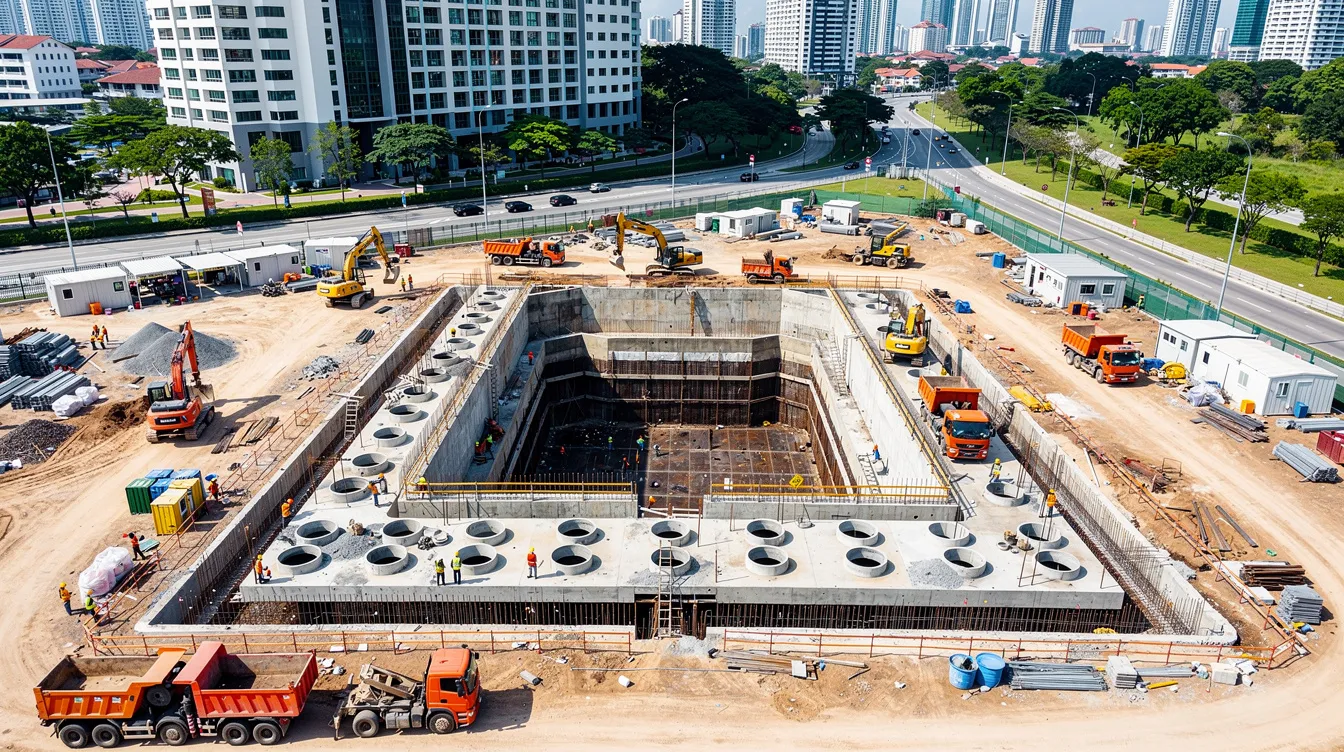
On-site detention (OSD) is a system, most often an underground tank, that temporarily holds peak runoff from a developed site and releases it at a controlled rate into the public drainage network. The purpose is straightforward: a new commercial building with extensive hardscape generates more runoff than the undeveloped or previously developed land it replaced. Without detention, that additional volume arrives at the public drain simultaneously, increasing flood risk downstream.
PUB’s flood-resilience strategy uses a Source-Pathway-Receptor framework. OSD sits at the “Source” level, managing runoff where it falls before it enters the public drainage system. “Pathway” measures (upgraded canals, widened drains) and “Receptor” measures (raised platform levels, flood barriers) handle what gets through. Since 2011, PUB has invested roughly S$2.5 billion in drainage improvements across these three layers. OSD tanks are the developer’s contribution to that system.
What Triggers On-Site Detention for Commercial Developments
A project of 0.2 hectares or larger must implement on-site stormwater detention if post-development peak runoff exceeds the maximum allowable discharge rate set under Clause 7.1.5 of PUB’s Code of Practice on Surface Water Drainage (Seventh Edition, December 2018, Addendum April 2021). Every site over 0.2 hectares needs a detention strategy evaluated by the PE.
Redevelopments that increase impervious area, even on sites below 0.2 hectares, can also trigger OSD when the change in runoff coefficient pushes peak discharge above the allowable rate. The PE confirms this early by comparing the site plan and gross floor area schedules against survey data and existing drainage records. This check typically happens during concept design, before the architectural layout locks, because relocating a detention tank after layout freeze has cascading effects on basement ramps, foundations, and external works.
Catchment analysis must be performed to determine runoff characteristics and drainage connections. The PE uses PUB’s published rainfall intensity curves and the Rational Method (Q = C × I × A / 360) to compute both developed peak runoff and allowable discharge. The maximum allowable discharge rate must be calculated to manage peak runoff; it is usually set equal to the pre-development peak runoff for the same site area.
Core Functional Requirements for Detention Tanks Under PUB
The Technical Guide for On-site Stormwater Detention Tank Systems outlines mandatory design criteria. Four requirements shape every PE’s approach:
-
Discharge cap. The tank must limit peak discharge to the pre-development or PUB-specified allowable rate, calculated per the Rational Method.
-
Four-hour recovery. PUB requires detention tanks to empty within four hours after the design storm ends. A detention tank must restore its full volume within four hours; both gravity and pumped systems must demonstrate this through a time-to-empty curve.
-
Overflow provisions. A safety overflow structure, sized for a runoff coefficient of 0.55, must provide a clear path to the public drain when the tank is full or controls malfunction. Submission drawings must show the overflow path explicitly.
-
Separation of shared volumes. If the tank also serves rainwater harvesting for non-potable uses or firefighting storage, the detention portion must empty independently within four hours. Separate accounting and labelling in drawings are mandatory.
The PE translates these into design tasks: hydraulic sizing, outlet control selection (orifice, weir, or pump), and performance checks. Both preliminary and detailed plans must include calculations and layout plans for tanks. The resulting documentation forms the core of the drainage submission package PUB reviews at the DP stage.
Roles and Responsibilities of the Professional Engineer
Endorsement responsibility splits by system type under PUB guidelines. A gravity system requires civil PE endorsement; a pumped system needs mechanical PE endorsement. On most commercial projects, both disciplines are involved:
-
Civil/structural PE: catchment delineation, hydraulic calculations and detention sizing, tank layout, outlet and overflow design, drainage plan preparation, and coordination with structural works (slab loading, waterproofing, groundwater uplift resistance).
-
Mechanical PE: pump selection with duty plus one standby redundancy, automated controls with manual override, standby power (generator), discharge pipe sizing, and control schematics for the PUB submission.
The qualified person’s statutory responsibilities include QP endorsement on all drainage plans, design calculations, deviation requests, and Certificates of Inspection at completion. The architect controls platform levels and building footprint; the contractor builds to drawings. The PE ensures technical adequacy and statutory compliance throughout. When site constraints force departures from PUB’s code, the PE prepares and defends the deviation application.
With these roles and triggers established, the next section traces the PE’s step-by-step design workflow from site assessment to buildable drawings.
From Early Concept to Buildable OSD Tank Design
Once OSD is confirmed as a requirement, the PE must lock in a concept that fits the site, the architectural layout, and PUB’s standards before formal submissions begin. Early coordination prevents submission delays and rework. These steps usually unfold between feasibility and detailed design, often before tender.
Stage 1: Site Assessment and Catchment Definition
The PE begins with data collection:
-
Topographical survey. Existing site levels, drainage outfall inverts, and the location of any drainage reserve or easement affecting tank placement.
-
Public drain records. PUB record plans showing invert levels, pipe sizes, and connection points for the nearest public drain. The difference between tank outlet invert and public drain invert determines whether gravity discharge is feasible.
-
Pre-development land use. Baseline runoff coefficients (ranging from approximately 0.45 for permeable landscape to near 1.0 for fully paved commercial surfaces) are needed to compute pre-development peak runoff.
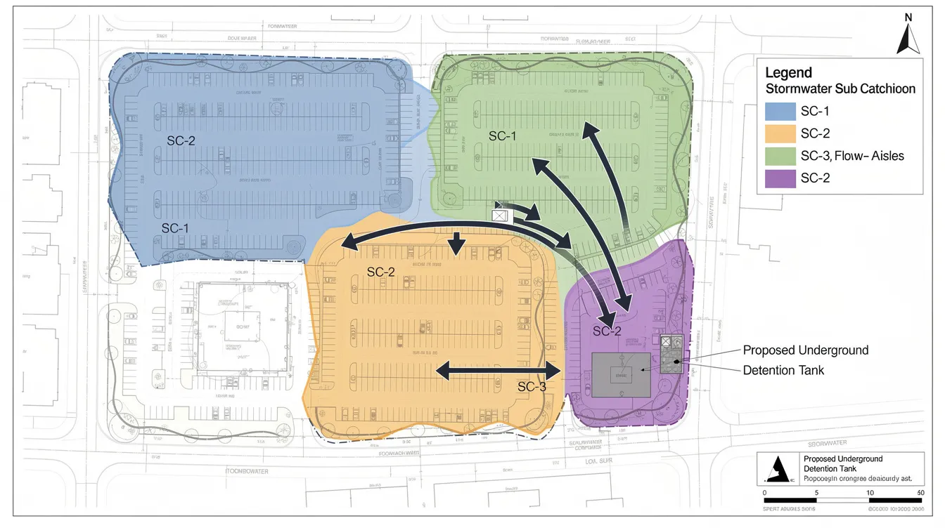
The PE then divides the development into sub-catchments: roofs, podium decks, landscape zones, driveways, and basement ramps. Each sub-catchment has distinct catchment characteristics, including area, surface type, and flow path to the detention tank. Cross-checking against architectural and landscape plans ensures every hardscape area feeding the tank is captured. Missing a loading bay or driveway extension at this stage forces recalculation later.
Stage 2: Choosing Tank Configuration and Discharge Strategy
Two core decisions define the tank concept:
Online vs. offline layout. An online tank sits directly in the main drainage path; an offline tank receives diverted flow via a side weir or diversion chamber. The PE evaluates based on site topography, catchment boundaries, and available footprint.
Gravity vs. pumped discharge. If the tank floor sits above the public drain invert with sufficient gradient, gravity discharge through a controlled orifice is the simplest and lowest-maintenance option. When basement depth, flat downstream drains, or constrained urban plots make gravity discharge impossible, the PE specifies a pumped system. Pumped detention systems require N duty + 1 standby pumps, automated operation with manual override, standby power via generator, and a swan-neck connection discharging to internal ground-level drainage rather than directly into a roadside public drain.
The PE consults the architect and structural engineer to select a location: under a driveway, below a plaza, or adjacent to basement levels. Geotechnical reports determine groundwater levels and whether uplift resistance requires additional structural measures. On one constrained site where the building entrance plaza was the only viable location, the project team had to redesign the structural transfer slab above the tank to accommodate both pedestrian loads and maintenance access. These coordination workshops are where the PE, architect, and structural engineer align on tank dimensions, cover depth, and access points.
Once configuration is agreed, the PE moves to detailed hydraulic sizing.
Stage 3: Hydraulic Sizing and Performance Checks
Hydraulic calculations and detention sizing are critical for determining stormwater management. The PE uses the Rational Method for small urban catchments (under approximately 40 hectares) or hydrologic/hydraulic modelling software for complex multi-catchment sites, applying PUB’s latest rainfall Intensity-Duration-Frequency curves.
The PE calculates three outputs:
-
Required detention volume for the design storm, sized so post-development peak Q does not exceed Q_allowable.
-
Outlet control dimensions: orifice diameter, weir length, or pump flow rate needed to throttle discharge to the allowable rate.
-
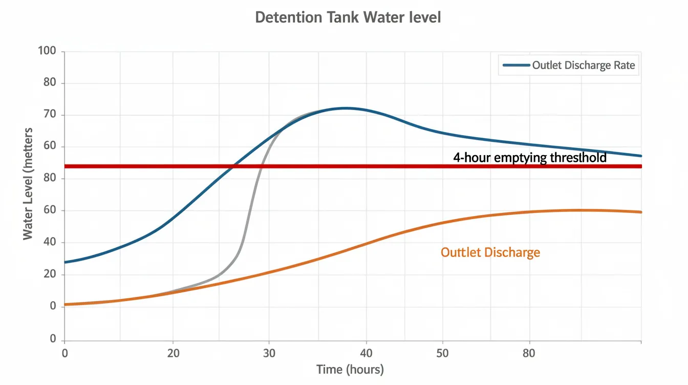
Time-to-empty curve demonstrating four-hour recovery from full storage. For pumped systems, this includes pump duty curves overlaid on tank drain-down profiles.
Conservative assumptions about orifice clogging (partial blockage factors), pump failure scenarios, and rainfall intensity during intense rainfall events are documented explicitly. PUB reviewers check these assumptions, so the PE includes a written justification for each one. Full hydraulic calculations accompany the submission, not just summary results.
With hydraulics confirmed, the PE coordinates structure, M&E, and access to produce buildable drawings ready for PUB submission.
Detailed Design, Coordination, and Documentation
This section shows how the PE converts concept and hydraulic sizing into fully coordinated drawings, M&E specifications, and documentation suitable for PUB, BCA, and other agencies. Interdisciplinary input is crucial for effective drainage system design; no single consultant produces all the information PUB needs to see.
Structural Layout, Access, and Maintainability
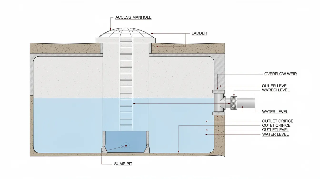
The civil/structural PE designs the tank geometry: slab thicknesses, internal baffles (if multi-chamber), access manholes, and sump pits. Coordination with the architectural layout above the tank determines column positions, pile locations, and load paths through the tank lid.
All access openings into the tank must be at ground level per PUB’s code of practice. Safe ladders, ventilation points, and internal walkways are specified so that MCST maintenance teams can inspect and clean the tank without confined-space entry complications. Watertightness detailing and uplift resistance (against groundwater buoyancy) are coordinated with the geotechnical engineer; on sites with high water tables, the structural PE may specify rock anchors or a heavier base slab.
Drawings must clearly show inspection openings, sump pits, drainage gradients within the tank floor, and safety features. These details appear in plan, section, and elevation views. Minimum platform levels can be around 4 meters above Singapore Height Datum on certain sites, which directly affects tank cover depth and access arrangements.
M&E Integration: Pumps, Controls, and Power (Where Applicable)
When a pumped discharge is needed, the mechanical PE’s scope expands considerably. Pump selection must match the controlled discharge rate while providing redundancy: one duty pump plus one standby, each capable of emptying the tank within four hours independently.
Control logic prioritises detention emptying after storms. Level sensors trigger pump start and stop sequences; a manual override panel allows operations staff to intervene. Standby power via a dedicated generator ensures the system operates during mains supply failure. The pump discharge connects to internal drainage at ground level via a swan-neck connection meeting minimum crest levels under Clause 2.2, not directly to the public drainage network.
The interface between civil and mechanical drawings requires particular attention: discharge pipe sizes, invert levels at pump sump and outlet, and backflow prevention devices must match across drawing sets. Clear control schematics and I/O lists are attached to the PUB submission for pumped systems. A gravity system requires civil PE endorsement; a pumped system needs mechanical PE endorsement, and both PEs sign off on the interface details.
Coordinating With ABC Waters Features and Rainwater Harvesting
The PE works with the landscape architect and M&E engineer to integrate features that reduce the volume reaching the detention tank. Bioretention planters, rain gardens, and vegetated swales designed to ABC Waters design guidelines absorb and filter initial runoff, lowering the peak volume the tank must handle. This can reduce tank dimensions and construction cost.
Rainwater harvesting systems for non-potable uses (irrigation, cooling tower makeup) may share the same physical tank or connect via a diversion valve. The PE ensures detention and harvesting volumes are accounted separately in calculations and clearly labelled in drawings, as PUB requires. The detention portion empties within four hours regardless of harvested water retained for reuse. AMAN Engineering models these options iteratively at preliminary design to right-size tank volume, avoiding overdesign that inflates construction cost.
With the design technically coordinated, the PE assembles the PUB submission package stage by stage.
Step-by-Step PUB Submission Workflow for Detention Tanks
A structured statutory submission process is essential for stormwater detention planning. Professional Engineers manage PUB submission workflows from initial assessments to final approvals. The process involves multiple stages including Development Control and Detailed Plan submissions, and a single development may require multiple agency approvals running in parallel.
Drainage Concept (DC) Stage: Establishing the OSD Strategy
Development control clearance is the first formal touchpoint with PUB. The agency reviews the high-level drainage concept, outfall points, and confirms feasibility of the OSD layout. DC clearance is required before DP clearance in submissions.
The PE typically prepares:
-
Site layout with proposed drainage design and tentative tank location marked.
-
High-level catchment plan showing sub-areas, assumed runoff coefficients, and preliminary allowable discharge calculation.
-
Key levels: site platform, public drain invert, proposed outlet invert, and the building entrance level relative to the drain.
-
A summary indicating whether the project scope triggers OSD under Clause 7.1.5.
AMAN Engineering normally aligns the DC timeline with URA planning approval and BCA concept submissions. Running these in parallel rather than sequentially prevents downstream clashes where, for example, URA conditions change platform levels after PUB has already cleared a gravity discharge concept that depended on those levels.
PUB typically responds to drainage submissions within 14 working days for a complete DC package.
Drainage Plan (DP) Stage: Detailed Hydraulic and Tank Design
The drainage plan is where PUB scrutinises detention tank sizing, flow controls, and emptying time. The PE leads the DP submission with:
-
Hydraulic calculation report. Design storm parameters, method (Rational Method or hydrologic model), catchment area breakdown, full hydraulic calculations including volume sizing, outlet control sizing, and the four-hour emptying check. Both preliminary and detailed plans must include calculations and layout plans for tanks.
-
Plan and section drawings. Tank geometry, inlets, outlets, overflow structure, and connection point to the public drain. Submission drawings must show the overflow path explicitly.
-
Pump and control schematics. For pumped detention systems: pump curves, control logic diagrams, I/O lists, standby power arrangement, and manufacturer datasheets.
-
Cover letter. A concise summary of the design approach, any deviation requests, and a checklist of enclosed documents.
The PE lodges the package via CORENET using PUB’s e-forms (PUB-DCCLR for DC, PUB-DPCLR for DP). Correct classification matters: confusing DC and DP submissions causes delays. If the project qualifies as a simplified submission (small A&A works meeting SS criteria), the PE uses that route, which receives acknowledgement within approximately one working day. Incorrect CORENET form selection resets submission position.
Amendment submissions require clouded drawings highlighting every change. PUB typically responds within 14 working days for a complete DP package.
Building Plan (BP) and Inter-Agency Coordination
While the building plan is not a PUB submission per se, misalignment between BP-approved structural works and the PUB-approved drainage plan is a frequent source of review queries during construction. The PE coordinates drainage and detention details with:
-
BCA for structural safety of underground tanks and adjacent foundations.
-
LTA if drains, external works, or the tank footprint encroach on road reserves or affect driveways.
-
NParks if drainage works sit under park connectors, tree conservation zones, or landscape features.
Coordination across agencies speeds up drainage submission approvals. Design teams must align architectural and drainage plans for compliance. AMAN Engineering uses BIM coordination to overlay the detention tank model with pile caps, utility corridors, and landscape features, catching clashes before they become site problems.
TOP and CSC: Completion-Stage Clearances
At temporary occupation permit (TOP) and certificate of statutory completion (CSC), PUB checks that built works match the approved drainage plan. The PE must conduct inspections during construction to verify compliance with approved designs, and at completion compiles:
-
As-built drawings with surveyed levels reflecting actual site conditions, including any approved deviations from the DP.
-
Functional test records. Pump tests demonstrating four-hour emptying performance, overflow operation, standby pump switchover, and generator start-up sequence (for pumped systems).
-
Signed Certificate of Inspection (COI) by the qualified person confirming works match the approved design.
-
Operations and Maintenance manual. The final handover requires an Operations & Maintenance manual for ongoing compliance. This includes standard operating procedures, inspection checklists, pump maintenance schedules, and emergency contact details for the design team.
The PE submits completion forms (PUB-DRATOP for TOP, PUB-DD-CSIDRA for CSC) alongside clearances from other agencies. PUB’s service commitment is 14 working days for technical clearance on complete packages. Regular maintenance of OSD tanks is mandated to ensure operational integrity, and property owners take over maintenance responsibility after CSC.
After covering the ideal workflow, the next section addresses recurring challenges and how the PE resolves them.
Common Challenges in PUB Detention Tank Submissions and How a PE Solves Them
Even with careful planning, OSD submissions encounter recurring technical and administrative issues. Each one below is paired with the PE’s practical mitigation strategy.
Conflicting Levels and Impossible Gradients
The problem surfaces when architectural planning fixes platform levels and basement ceiling heights before the PE has confirmed drain invert levels. On one type of constrained project, the building entrance sits at a level that leaves the tank outlet above the public drain invert, making gravity discharge geometrically impossible. Minimum platform levels may reach 4 meters above Singapore Height Datum on flood-prone sites, compressing the available gradient between tank floor and drain connection.
The PE resolves this through early coordination workshops with the architect and structural engineer, held before site levels are locked. If gravity discharge remains unworkable, the PE switches to a pumped system and prepares a technical justification for PUB showing that redundancy, standby power, and overflow provisions meet code requirements. Late design changes can block approved drainage routes; the earlier the PE establishes discharge strategy, the fewer costly redesigns follow.
Incomplete or Inconsistent Submission Packages
Missing PE endorsements on drawings leads to submission rejections. Mismatched drainage plans and hydraulic calculations trigger questions that add another review cycle to the timeline. Unclouded amendments on resubmissions cause PUB reviewers to request a full re-comparison, adding further weeks.
The PE’s countermeasures: an internal checklist cross-referencing tank volume, outlet size, invert levels, pump specs, and calculation outputs against every drawing sheet before lodgement. AMAN Engineering uses standardised templates for hydraulic reports and cover letters that enforce a single “storyline” across plans, sections, and calculations. Incomplete connection proposals stall drainage submissions; the checklist catches missing outfall details, road-crossing approvals, and M&E interface drawings before the package reaches CORENET. A structured compliance workflow reduces the chance of omissions.
Site Constraints and Deviation from Code Requirements
On constrained urban plots, strict compliance with PUB’s code is sometimes physically impossible. Examples include heritage basements where excavation depth is restricted, existing underground utilities crossing the proposed tank footprint, or shallow public drains where the receiving invert is higher than expected from record plans.
The PE prepares a deviation application containing: the specific clause that cannot be met, the physical reason (with survey evidence), the proposed alternative design (e.g., redistributed catchments, deeper pump sump, relocated overflow), a risk assessment comparing the alternative against code-compliant performance, and mitigation measures. Engaging PUB in a pre-submission meeting to obtain informal feedback before formal lodgement reduces rejection risk. AMAN Engineering’s experience with past deviation approvals, across commercial, institutional, and mixed-use projects, informs these proposals with precedent-based reasoning that PUB reviewers recognise.
Technical compliance is crucial throughout the submission and construction stages for detention systems. Proactive PE involvement and structured processes are the best defence against these challenges.
Conclusion and Next Steps
A professional engineer manages PUB submission for on-site detention tanks end to end by confirming OSD triggers early, defining catchments with verified survey data, designing and coordinating hydraulics alongside structural and M&E disciplines, preparing clear DC/DP/TOP packages, and managing PUB queries through to CSC clearance. Detailed structural and hydraulic designs must be documented at every approval stage.
Practical next steps:
-
Verify your trigger status. Check whether your site area and development type require OSD under current PUB requirements based on the 0.2-hectare threshold and post-development runoff.
-
Engage a PE early. Bring in a civil/structural PE before architectural layout and platform levels are frozen to plan tank location and discharge strategy.
-
Assemble existing data. Gather topographical surveys, PUB drainage records, and GFA schedules to support catchment analysis from day one.
-
Align your submission schedule. Map PUB DC/DP milestones against URA, BCA, LTA, and NParks timelines so that inter-agency coordination runs in parallel, not in series.
-
Review stalled projects. If your current drainage submission has been queried or rejected, a diagnostic review by an experienced PE can identify the root cause and the shortest path to PUB approval.
Related topics that interact with OSD design, including authority submission for sewerage, fire safety, and BCA structural submissions, are covered in separate guides.
How AMAN Engineering Consultancy Supports End-to-End OSD PUB Submissions
AMAN Engineering Consultancy Pte Ltd provides integrated civil, structural, and M&E endorsement along with full PUB authority submission management for commercial projects with detention tanks in Singapore. The firm’s PEs handle every stage described in this article, from the first catchment study to the final O&M manual handover at CSC.
Specific capabilities include:
-
Catchment studies, hydraulic modelling, and detention tank right-sizing using PUB’s latest codes and the Technical Guide appendices.
-
BIM-based coordination of underground tanks with foundations, utilities, and landscape features to eliminate clashes before construction works begin.
-
Preparation and lodgement of PUB DC/DP submissions via CORENET, including deviation applications where site constraints demand them.
-
On-site inspections, functional testing, and O&M manual preparation for TOP/CSC drainage clearance.
-
Liaison with statutory boards (BCA, LTA, NParks, URA) for projects where drainage works intersect with other agencies’ jurisdictions.
If your project is at concept stage or your current submission needs a course correction, contact AMAN Engineering for a preliminary OSD and drainage submission review.
Frequently Asked Questions on PUB Submission for Detention Tanks
These are questions clients frequently ask AMAN’s engineers about PUB detention tank submissions.
Do I always need a Professional Engineer for a PUB detention tank submission?
Yes. Any drainage submission involving on-site detention tanks requires a qualified person (typically a civil/structural PE, plus a mechanical PE for pumped systems) to design and endorse the submission under the Sewerage and Drainage Act. Non-PEs can assist with drafting and administrative tasks, but statutory responsibility for the drainage design rests with the QP. This applies to all project types, whether a terrace house redevelopment or a large commercial development; if a detention tank is involved, PE endorsement is mandatory.
How long does PUB usually take to clear a detention tank submission?
PUB typically responds to drainage submissions within 14 working days for a complete DC, DP, or TOP/CSC package. This timeline assumes no major queries. Clear, coordinated submissions with consistent drawings, full hydraulic calculations, and proper PE endorsements minimise queries during the PUB review and reduce overall approval time. Complex projects or deviation requests may extend the review cycle.
Can we combine our detention tank with rainwater harvesting or firefighting storage?
Combined use is permitted but follows strict rules. The detention volume must be clearly separated from harvesting or firefighting volumes in both design and operation. The detention portion must still empty within four hours independent of water retained for reuse. The PE prepares clear schematics showing volume allocation, valve or weir separation, and control logic so that PUB can verify compliance. Rainwater harvested for non-potable uses (irrigation, cooling tower makeup) does not count toward the detention recovery volume.
What happens if site conditions change after PUB has approved the detention design?
Changes to basement depth, tank location, outfall level, or catchment boundaries after PUB approval typically require an amendment submission. The PE reassesses hydraulics with the revised parameters, updates detailed drawings, clouds all amendments, and provides written justification for PUB’s review. Construction must not proceed on the changed elements until PUB clears the amendment. Late design changes can block approved drainage routes, so the PE flags any proposed modifications against the approved drainage plan before the project team commits to them.
At what stage of my project should I involve AMAN Engineering for OSD design and PUB submission?
Engage AMAN at concept design or early schematic design, ideally before platform levels, basement extents, and major utility corridors are fixed. At that stage, the design team still has flexibility to optimise tank location, discharge strategy, and tank dimensions without triggering costly redesign. For food establishments, industrial facilities, or mixed-use commercial developments on constrained sites, early PE involvement is the difference between a smooth lodgement-based submission process and months of rework.