
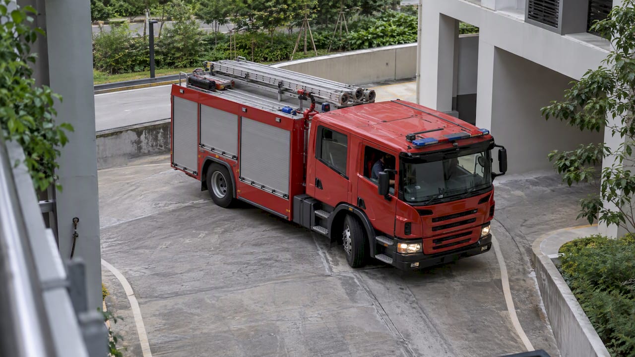
Under SCDF Fire Code 2023 Clause 4.2, fire engine accessway requirements turn on a short set of checks: clear width by building use and habitable height, gradient (accessway 1:15, access road 1:8.3), dead ends beyond 46m, a 2m to 10m façade distance, overhead clearance and breeching inlet placement. Confirm the applicable table first, then have your Qualified Person annotate each value on the plan.
TL;DR:
- For many purpose groups, accessway length must cover one quarter of the building perimeter, with a 15 m minimum; specific Table 4.2.2a values override that rule.
- A dead end longer than 46 m requires the turning facility in Diagram 4.2.2e; show clear dimensions and a turning template on the plan.
- Accessways over suspended slabs need calculations against Tables 4.2D and 4.2E, because fire appliance axle and jack loads can exceed ordinary traffic design assumptions.
- Openings must measure at least 850 mm by 1 m, with sills no higher than 1.1 m and heads at least 1.8 m above the floor.
- Overhead crossings must provide 4.5 m clearance, be no wider than 10 m, and leave the final 20 m of accessway unobstructed.
Table of Contents
- What are the SCDF fire engine accessway requirements at a glance?
- How do you size accessway length and provide turning facilities?
- What gradients and surface treatments does SCDF allow?
- Where should the accessway sit relative to the façade, hydrants and breeching inlets?
- What size must fire access openings be, and how are they spaced?
- When can overhead structures cross an accessway?
- Which common audit failures should a QP check before submitting?
- How does a Qualified Person apply Clause 4.2 in practice?
- Why designing to the SCDF numbers early saves time and cost
- How we help with SCDF accessway compliance
- FAQ
- Sources
What are the SCDF fire engine accessway requirements at a glance?
The thresholds designers consult most often sit in Clause 4.2, which defines how a site must be laid out for appliance access. The widths, loading bands and length minima depend on the purpose group (PG) and habitable height, so the first step is always to identify which of Tables 4.2A, 4.2B and 4.2C applies. Habitable height is measured from the lowest access level to the highest habitable floor, a definition set out in the Code of Practice for Fire Precautions in Buildings 2023.
Loading is the second discriminator. Clause 4.2 sets structural capacity bands of more than 24 tonnes, more than 30 tonnes and more than 50 tonnes, depending on PG and habitable height. Axle and jack loads for the heavier appliances are covered in Tables 4.2D and 4.2E. The clear widths in the tables vary by building use and habitable height, while a fire engine access road must be at least 4m wide.
| Parameter | Requirement |
|---|---|
| Fire engine access road, minimum width | 4m |
| Accessway clear width | Per Tables 4.2A, 4.2B and 4.2C |
| Accessway gradient, maximum | 1:15 |
| Access road gradient, maximum | 1:8.3 |
| Dead-end length before turning facility | 46m |
| Accessway to fire access opening | 2m to 10m |
| Wet hydrant proximity to any part of accessway | Within 50m |
| Breeching inlet distance from accessway | Within 18m |
| Overhead clearance, minimum | 4.5m |
| Loading capacity bands | More than 24 tonnes, more than 30 tonnes, more than 50 tonnes |
Breeching inlets are governed by Clause 4.3, which requires them to be visible from the accessway so that a single hose length suffices.
How do you size accessway length and provide turning facilities?
Required accessway length is derived from the building perimeter or the extent of the compartment served. For many purpose groups the rule is a fraction of the perimeter, expressed as a quarter of its length, subject to a minimum of 15m. Where Table 4.2.2a gives specific values for a use group, those values govern instead. State the perimeter computation on the plan, including the measurement lines, so that the reviewer can verify the arithmetic without a query.
Perimeter definitions occasionally cause disputes, particularly for podium blocks and irregular footprints. Our practice is to show the perimeter as a dimensioned polyline and cross-reference it to the applicable table row. Developers with several blocks sharing a podium may find our fire access roads design guide a useful companion on radii and loads.
Dead ends carry a firm limit. A dead-end accessway or access road longer than 46m must incorporate a cul-de-sac turning facility, dimensioned according to Diagram 4.2.2e. Show the required turning facility where the dead-end limit is exceeded. The Diagram 4.2.2e geometry is also reproduced in the Clause 4.2 page for related SCDF codes, and practitioners use these diagrams to determine turning facilities.
Practical points for turning design:
- Overlay an appropriate turning template on the plan for the appliances the tables assume.
- Show the full cul-de-sac footprint of Diagram 4.2.2e, including its clear dimensions, rather than a schematic arrow.
- Check that bollards, planters and kerb returns do not intrude on the swept path.
- Confirm that any gate or barrier at the entry preserves the clear width required by the applicable table.
- Where the accessway is a through route, state that no dead end exists so that the 46m rule is visibly addressed.
Appliance deployment needs should be considered when coordinating width, gradient and turning geometry. That is why width, gradient and turning geometry are specified together and not as isolated numbers.
What gradients and surface treatments does SCDF allow?
Gradient limits are specific to the type of route. Per Clause 4.2, a fire engine accessway must be laid on a level platform or an incline not exceeding 1:15, while a fire engine access road is permitted an incline not exceeding 1:8.3. The distinction matters because an accessway is where heavier appliances deploy, and an appliance parked on a steeper slope cannot safely extend ladders or outriggers.
Surfacing is the second recurring audit theme. The SCDF Common Audit Issues document notes that turfing is allowed only on straight accessway stretches with a gradient not exceeding 1:15. Turfed sections on a curved run, or on a steeper incline, are flagged for correction.
What to check on gradient and surfacing:
- Confirm the critical run, meaning the steepest continuous stretch, rather than only the average slope.
- Label the gradient value on each segment of the route where levels change.
- Keep turfed areas to straight stretches and state the 1:15 limit beside them.
- Keep obstructions out of the accessway footprint.
- Where the accessway crosses a suspended slab or basement roof, include the loading calculation against the Table 4.2D and 4.2E values.
Structural loading deserves early attention. Fire appliance jack and axle loadings differ from those of ordinary commercial vehicles, so a slab designed only for general traffic may need strengthening. Substituting an access road specification for an accessway is a compliance failure that can force remedial structural work late in the programme.
Pro Tip: Ask your structural engineer to confirm the characteristic loading band for the accessway before the architectural layout is frozen, since a late change in slab capacity is far costlier than a change in kerb alignment.
Where should the accessway sit relative to the façade, hydrants and breeching inlets?
Positioning rules exist to minimize the hose length crews need and to let them find inlets quickly. Three measurements dominate, and each should appear as a dimensioned line on the plan.
- Façade distance: the nearer edge of the accessway, measured horizontally, must lie between 2m and 10m from the centre of the fire access opening. Draw the measurement line from the accessway edge to the opening centre, not to the façade face.
- Hydrant proximity: every part of the accessway or access road should be within 50m of a wet fire hydrant. Where no public hydrant is available within that distance, provide private hydrants and show their positions and the 50m radius.
- Breeching inlets: for buildings with rising mains and automatic sprinklers, Clause 4.3 requires inlets to be sited within 18m of the accessway or access road and visible from it, so that only one hose length is needed.
Breeching inlet visibility is a frequent source of failure. An inlet that is technically within 18m but hidden behind a landscaped screen, a signage structure or a parked-vehicle bay will draw a comment. Show the sight line on the plan and keep the approach unobstructed.
Perimeter-based length calculations also depend on how floor areas and boundaries are measured. If you are reconciling those figures against planning submissions, this explanation of gross floor area calculation in Singapore shows how the underlying metrics are derived.
Coordinate the accessway alignment with drainage, utilities and tree planting from the outset. Manholes, planter beds and lamp posts placed inside the clear width reduce the usable dimension below the table value, which is a more common cause of rework than a wrong table selection.
What size must fire access openings be, and how are they spaced?
Fire access openings give firefighters a way into the building from the accessway side, so their dimensions and clear zones are specified closely. The minimum opening is 850mm wide by 1m high. The sill must not exceed 1.1m above the floor and the head must be at least 1.8m above it, so that a person can climb through and equipment can pass.
A clear area outside the opening must also be maintained, with a minimum width of 3.5m and height of 2.5m. This clear zone keeps ladders, hose lines and personnel from being obstructed by balconies, planters or fixed canopies.
Dimensional and spacing points to apply:
- Provide and distribute fire access openings or access panels as required by Clause 4.2.
- Distribute openings by centre-to-centre spacing rather than clustering them at one end of the façade.
- Show each opening on the plan with a symbol and dimension note, since the Common Audit Issues document lists missing fire access openings among frequent errors.
- Ensure fire access openings remain accessible.
- Keep openings clear of obstructions such as shelving, signage and display units.
Spacing interacts with the 2m to 10m rule discussed above. An opening that is conveniently spaced but sits 12m from the nearer edge of the accessway fails the distance requirement, so check both conditions together on each elevation. Where the façade is heavily glazed, discuss suitable access panel arrangements with the Qualified Person.
Operational maintenance matters after handover. Building management should check that access openings remain unobstructed.
When can overhead structures cross an accessway?
Canopies, linkways and signage gantries are common conflicts with accessway alignment. Clause 4.2 permits overhead structures over an accessway only under defined conditions, and each one must be visible on the plan.
The conditions are an overhead clearance of at least 4.5m, an overhead structure width of no more than 10m, and a final 20m of accessway that is entirely free of overhead structures. That last stretch is where appliances position for deployment, so ladders and platforms need unrestricted headroom.

For plan annotation, show the extent of each overhead structure in plan and section, state the clearance height as a dimension and mark the 20m end stretch with a note confirming that nothing crosses it. A reviewer looking at an unlabeled canopy outline cannot tell whether the clearance is 4.5m or 3.5m, and will ask.
Atypical structures, such as a long covered drop-off that extends well beyond 10m or a bridge-like linkway at variable height, may need further SCDF discussion or supporting diagrams. Raise these early. Our guide to the SCDF Fire Code covers how such cases are normally escalated and documented.
Which common audit failures should a QP check before submitting?
The SCDF Common Audit Issues document lists frequent plan errors, including failing to indicate accessway versus access road, incorrect turfing, missing fire access openings and inconsistent legends. In our experience, breeching inlet visibility and distance are also repeat comment items, and labeling errors between the two route types trigger resubmissions because each has distinct requirements.
A numbered pre-submission checklist helps remove these errors:
- Label every route as either fire engine accessway or fire engine access road, using one consistent legend across all drawings.
- Attach the table references (4.2A, 4.2B or 4.2C) beside each computed width and length.
- Show turning templates and the Diagram 4.2.2e cul-de-sac wherever a dead end exceeds 46m.
- Dimension the 2m to 10m measurement line from accessway edge to opening centre.
- Mark all hydrants with the 50m radius and all breeching inlets with the 18m distance and sight line.
- Indicate every fire access opening, with sill, head and clear zone dimensions.
- Show overhead structures with clearance height and the 20m free end stretch.
- Confirm gradient values for each segment and limit turfing to straight stretches at 1:15 or flatter.
- Include loading calculations where the accessway sits on a suspended slab, referencing Tables 4.2D and 4.2E.
- Photograph existing site constraints, such as trees, level changes and neighboring structures, and keep the record on file.
Plans must be prepared and submitted by a Qualified Person, with plan fees and a QP declaration, as set out in SCDF’s Plan Approval guidance. Our QP’s guide to SCDF plan submission and the QP architectural plan submission page expand on the documentation expected.
Pro Tip: Add a short plan note quoting the exact clause and table used to compute each width and length, so the reviewer can verify the basis in seconds.
How does a Qualified Person apply Clause 4.2 in practice?
The Qualified Person begins by identifying the correct table. Purpose group and habitable height determine whether Table 4.2A, 4.2B or 4.2C governs, and the habitable height definition in the Code of Practice fixes where the measurement starts. A wrong table choice propagates through every dimension that follows, so this step deserves a documented rationale.
Documentation then follows a repeatable pattern. Annotate the plan with table references, show measurement lines for the 2m to 10m rule, present the perimeter computation as a dimensioned figure and attach turning-diagram overlays. Consistency of legend between architectural, structural and fire safety drawings avoids the mislabeling errors described above.
Site survey priorities complete the picture. Measure gradients along the critical run, test bearing capacity where the accessway sits on a slab or fill, and verify sight lines to breeching inlets from the intended appliance position. Record each finding with photographs and dated notes, since evidence gathered early supports the submission and any later query. Where structural loading is in doubt, our note on how fire safety certification connects with structural engineering explains the dependency.
Why designing to the SCDF numbers early saves time and cost
Most accessway problems are cheap to fix on a sketch and expensive to fix on a built slab. A gradient correction, a relocated breeching inlet or a shortened canopy costs little before drawings are issued. After construction, the same change can require demolition, re-casting or a revised structural design.
In my view, the real saving comes from treating Clause 4.2 as a coordination problem and not a drafting exercise. The architect controls alignment, the structural engineer controls loading, the fire safety consultant controls inlets and hydrants, and each assumes another has checked the shared numbers. When those assumptions are tested together in one early review, resubmission cycles drop and the programme becomes more predictable. Our team coordinates QP sign-off, structural loading and SCDF plan-ready annotations in a single workflow for exactly this reason.
— Aman
How we help with SCDF accessway compliance

Passing review on the first submission protects your programme, and we structure our work to make that outcome likely. Our team supports owners, developers and design professionals on fire engine accessway compliance through the following services:
- Authority approvals and SCDF plan submissions, including Fire Safety Certificate assistance
- Structural inspections and loading calculations for accessways on slabs
- Site surveys covering gradients, bearing capacity and inlet visibility
- Qualified Person declaration and plan annotation to Clause 4.2 requirements
- BIM and shop drawing coordination across architectural, structural and fire disciplines
Send us your site plan and we will run a pre-submission QP check and, where useful, a site survey, so that table references, measurements and loading notes are in order before SCDF sees them. Start with our authority approvals and Fire Safety Certificate services or contact us through our website.
FAQ
What is the minimum size required for a fire engine accessway?
The minimum clear width depends on the purpose group and habitable height, as set out in Tables 4.2A, 4.2B and 4.2C of Clause 4.2. Typical table values are 6m or 7m, and length is derived from the perimeter rule, with a minimum of 15m for many groups.
What are the requirements for a fire engine access road according to the SCDF?
A fire engine access road must be at least 4m wide and may be laid on an incline not exceeding 1:8.3, per Clause 4.2. It is intended for appliance travel within a development, and a dead end longer than 46m needs a cul-de-sac turning facility.
What is the minimum clearance required for overhead structures above an accessway?
Overhead clearance must be at least 4.5m, with overhead width limited to 10m and the final 20m of the accessway kept free of any overhead structure. Show all three conditions as dimensions on the plan.
What is the minimum road width for fire engine access?
For a fire engine access road the minimum width is 4m. A fire engine accessway follows the larger clear widths in Tables 4.2A, 4.2B and 4.2C, since it serves heavier appliance deployment.