
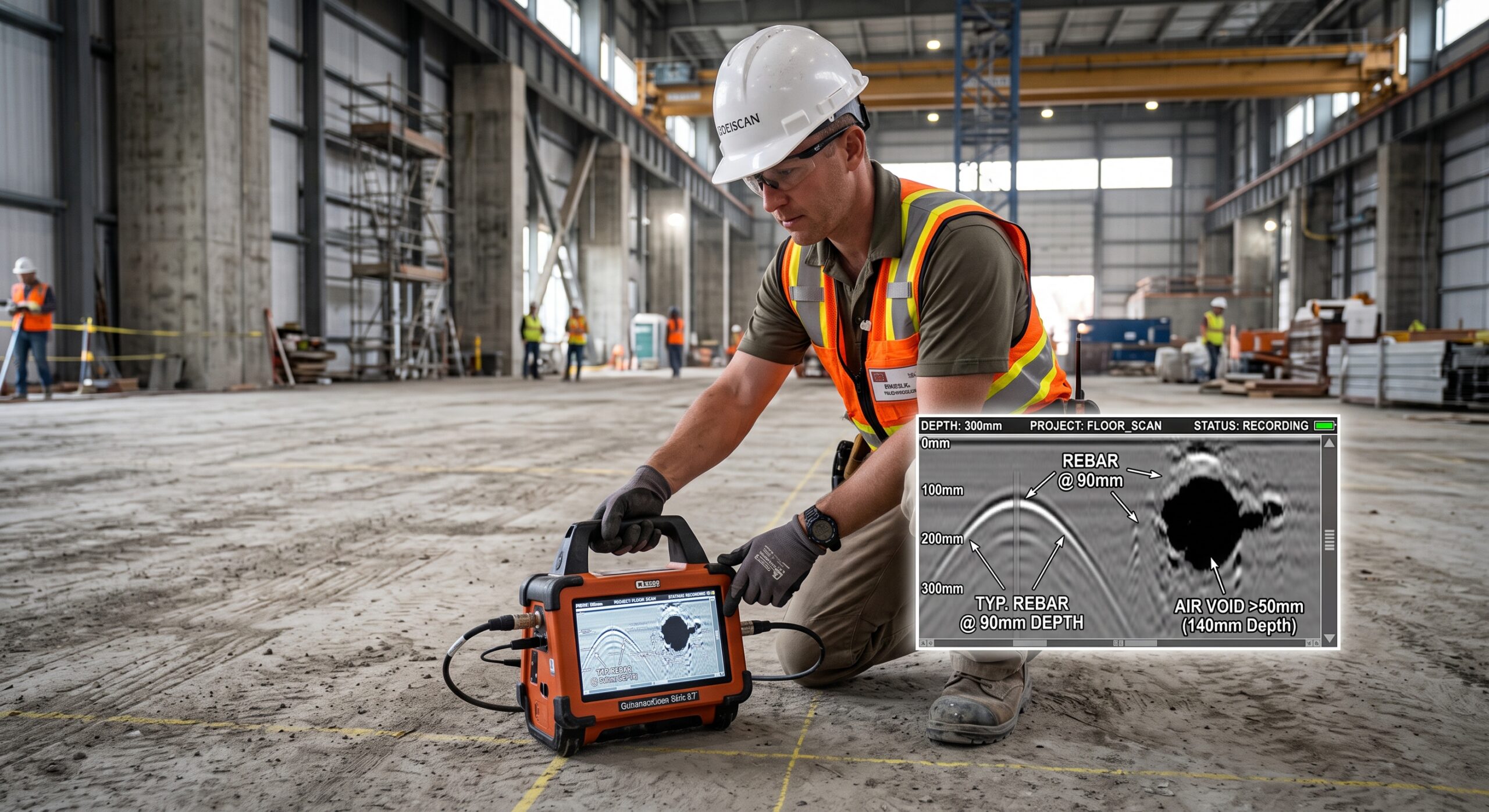
The Imperative of Advanced Non-Destructive Testing in Complex Modern Infrastructure
Ground Penetrating Radar (GPR) has unequivocally established itself as an absolutely indispensable non-destructive testing methodology utilized heavily by structural engineers and geophysical technicians across the globe for the meticulous evaluation of aging concrete infrastructure prior to the commencement of invasive coring, cutting, or anchoring operations1.
By forcefully transmitting ultra-short pulses of high-frequency electromagnetic energy directly into a heterogeneous subsurface medium, this remarkably advanced diagnostic technology successfully captures the resultant reflected waves that bounce back upon encountering internal structural boundaries characterized by highly significant differences in their respective electromagnetic properties1.
The overarching diagnostic objective of implementing this sophisticated technology within civil engineering, commercial facility maintenance, and industrial structural rehabilitation sectors is to proactively detect deep voids and honeycombing using Ground Penetrating Radar (GPR), thereby providing critical, life-saving intelligence regarding the exact three-dimensional spatial positioning of embedded steel reinforcement grids, highly stressed post-tensioned cables, and potentially hazardous subterranean utility conduits1.
As modern commercial and industrial infrastructure continuously ages and subsequently deteriorates under the relentless, uncompromising application of massive static and dynamic operational loads, establishing a rigorously validated framework for comprehensive non-destructive structural evaluation has become a paramount concern for maintaining unyielding public safety and strict regulatory compliance4.
Conducting an exhaustively detailed, high-resolution scan of a concrete floor slab, heavy foundation pad, or suspended bridge deck prior to any inherently destructive mechanical coring operation is absolutely essential for avoiding catastrophic subterranean utility strikes, preventing the accidental and potentially lethal severing of load-bearing post-tensioned tendons, and mitigating the associated astronomical financial risks of profound structural failure or severe operational facility downtime2.
This exhaustively detailed technical report meticulously delineates the theoretical physics governing electromagnetic wave propagation through complex, multi-phase concrete matrices, explicitly detailing the optimal operational parameters required for mapping rebar depths accurately while simultaneously identifying incredibly insidious subsurface anomalies such as massive volumetric air voids and structurally compromising concrete honeycombing2.
The Fundamental Physics Governing Electromagnetic Wave Propagation and Reflection
To truly comprehend the remarkably nuanced capabilities and the inherently inescapable physical limitations of Ground Penetrating Radar systems when attempting to accurately detect deep voids and honeycombing within structural elements, one must first master the underlying electromagnetic physics that dictate the complex behavior of radar waves as they traverse heterogeneous, multi-phase materials such as heavily reinforced concrete1.
The foundational, unalterable physical principle dictating the diagnostic functionality of all commercial GPR systems relies exclusively upon the detection of stark contrasts in the relative dielectric permittivity existing between the primary host concrete matrix and any embedded subsurface anomalies, regardless of whether those anomalies consist of highly conductive metallic elements like steel rebar or non-metallic inclusions such as air-filled voids, moisture-saturated cracks, or synthetic polyvinyl chloride plumbing conduits2.
Dielectric Permittivity, Conductivity, and the Reflection Coefficient
Every discrete, definable material present within the physical universe possesses a uniquely quantifiable electromagnetic property known universally as relative dielectric permittivity (frequently denoted within geophysical literature as the dielectric constant, ), which fundamentally and irrevocably determines the specific velocity at which an electromagnetic wave can physically propagate through that particular encompassing medium10.
When completely dry and fully cured under optimal environmental conditions, standard structural concrete typically exhibits a relative dielectric permittivity ranging roughly between 6 and 8, whereas the uncompressed atmospheric air—which commonly and dangerously fills the deleterious subsurface voids, massive sinkholes, and honeycombed regions—possesses a relative dielectric permittivity closely approximating the baseline value of 12.
Because standard carbon steel reinforcing bars essentially exhibit an effectively infinite electrical conductivity, they functionally act as perfect electromagnetic reflectors, aggressively bouncing virtually all of the incoming high-frequency energy directly back toward the surface receiving antenna and thereby producing remarkably strong, exceptionally high-contrast visual signatures on the resulting processed radargram2.
The exact proportion of electromagnetic energy that is successfully reflected back to the surface-mounted receiving antenna upon violently striking an internal structural interface is mathematically determined by calculating the reflection coefficient (), which is derived utilizing the distinct dielectric permittivities of the adjacent abutting materials according to the following firmly established physical relationship:
Where the variable precisely represents the relative dielectric permittivity of the primary host medium (for example, the solid concrete matrix) and the variable accurately represents the relative dielectric permittivity of the embedded target object (for example, a cavernous air void, a plastic utility conduit, or localized moisture ingress). Consequently, when a transmitted electromagnetic pulse abruptly transitions from a solid, cured concrete matrix () directly into a distinct, hollow air void (), the exceedingly substantial numerical contrast generates a highly recognizable reflection signature, characterized predominantly by a specific negative phase shift that extensively trained geophysical analysts actively utilize to definitively differentiate completely empty cavities from highly conductive, moisture-filled structural delaminations2.
Wave Velocity, Rigorous Depth Calibration, and Signal Attenuation Mechanics
In order to successfully and reliably map rebar depth and simultaneously calculate the exact vertical spatial position of dangerous subsurface anomalies prior to authorizing destructive coring operations, the diagnostic software system must accurately convert the measured two-way travel time (TWTT) of the reflected electromagnetic pulse into a highly precise physical depth measurement1.
The specific propagation velocity () of the emitted radar wave as it travels downward through a specific heterogeneous medium is directly and inversely proportional to the square root of that particular material’s relative dielectric permittivity and relative magnetic permeability (), calculated via the following standard geophysical equation where invariably represents the universal speed of light propagating in a perfect vacuum:
By meticulously and systematically analyzing the two-way travel time of the Ground Penetrating Radar signal solidly reflected from the distinctly known back boundary of a suspended concrete slab or a massive retaining wall, and concurrently knowing or accurately estimating the specific dielectric permittivity of the cured concrete, skilled operators can establish a highly accurate, structure-specific depth calibration curve for the entirety of the diagnostic survey3.
However, it is an inescapable physical reality that electromagnetic waves are inevitably subjected to severe exponential signal attenuation as they continuously propagate downward through any real-world heterogeneous material, a phenomenon primarily and aggressively driven by the localized electrical conductivity of the concrete matrix and the specific operational center frequency deliberately utilized by the transmitting antenna1.
In low-loss dielectric materials, the specific attenuation coefficient () can be accurately determined by utilizing complex mathematical approximations that carefully incorporate the magnetic permeability (), electrical conductivity (), real dielectric permittivity (), and the specific angular frequency () of the transmitted electromagnetic pulse8.
Excessively high electrical conductivity, which is very frequently exacerbated by elevated internal moisture content or the catastrophic, long-term infiltration of highly corrosive chloride ions stemming from aggressive winter de-icing salts or harsh coastal marine environments, drastically reduces the maximum achievable signal penetration depth by prematurely absorbing the radar waves long before they can physically reach and illuminate the much deeper structural targets1.
Furthermore, rigorous environmental studies consistently demonstrate that variations in ambient cold temperatures can significantly alter the moisture states within underlying soils and exposed concrete, subsequently modifying the relative dielectric constant and severely complicating the long-term repeatability and consistency of GPR imaging results across different seasonal testing windows6.
| Structural Material or Subsurface Element | Relative Dielectric Permittivity (ϵr) | Expected Electrical Conductivity (σ in mS/m) | Approximate Radar Wave Velocity (v in m/ns) |
| Atmospheric Air (Deep Subsurface Voids) | 1.0 | 0.0 (Perfect Insulator) | 0.300 |
| Intact, Dry, Fully Cured Structural Concrete | 6.0 – 8.0 | 1.0 – 5.0 | 0.106 – 0.122 |
| Wet, Heavily Moisture-Saturated Concrete | 10.0 – 20.0 | 10.0 – 50.0 | 0.067 – 0.095 |
| Fresh Water (Signaling Severe Moisture Ingress) | 80.0 | > 10.0 | 0.033 |
| Carbon Steel (Rebar Mats / PT Cables) | Infinite (Perfect Conductor) | > | 0.000 (Complete Electromagnetic Reflection) |
Selecting the Optimal Antenna Frequency: The Inescapable Resolution Versus Depth Paradigm
One of the absolute most consequential technical determinations that a qualified geophysical operator must meticulously execute when preparing to comprehensively detect deep voids and honeycombing using Ground Penetrating Radar (GPR) revolves entirely around the deliberate, highly calculated selection of the optimal antenna center frequency for the specific structural asset under investigation1.
The overarching, universally acknowledged operational paradigm governing absolutely all Ground Penetrating Radar applications dictates a fundamentally inescapable physical trade-off between the maximum achievable vertical depth of electromagnetic signal penetration and the fundamental spatial resolution necessary for accurately discerning microscopic structural details1.
Deploying High-Frequency GPR Systems (2.0 GHz to 2.7 GHz) for Shallow Precision
When the primary diagnostic objective of the engineering investigation involves conducting highly detailed, millimeter-accurate structural concrete inspections, mapping the precise geometric layout of remarkably shallow rebar mats, or thoroughly scanning a typical suspended commercial building slab prior to authorizing hazardous mechanical coring operations, the deployment of ultra-high-frequency antennas operating precisely between the 2.0 GHz and 2.7 GHz spectrum represents the universally accepted and mandated industry standard2.
Because these significantly elevated transmission frequencies natively generate exceptionally short electromagnetic wavelengths, they naturally possess an absolutely phenomenal spatial resolution capability, thereby reliably enabling the unambiguous detection of incredibly minute targets such as small-diameter electrical lighting conduits, tightly spaced structural reinforcing steel bars, and the exceedingly thin, highly destructive horizontal air gaps that are characteristically indicative of early-stage structural delaminations2.
Industry-leading hardware platforms, such as the widely utilized GSSI StructureScan Mini XT operating powerfully at 2.7 GHz, routinely acquire incredibly dense 3D grid datasets over heavily congested structural areas, allowing analysts to meticulously trace diagonal electrical cables meandering dangerously through incredibly dense welded mesh overlaps12.
However, the completely unavoidable physical consequence of employing such aggressively high-frequency electromagnetic transmissions manifests profoundly in a severely constrained maximum vertical penetration depth, which typically tops out abruptly at approximately 300 to 400 millimeters within standard, fully cured, relatively dry structural concrete matrices2.
Utilizing Mid-Frequency GPR Systems (1.0 GHz to 1.6 GHz) for Balanced Diagnostic Assessment
For highly critical structural assessments requiring rigorous geophysical investigation extending far beyond the superficial primary reinforcement layers, such as evaluating massively thick highway bridge decks, substantial earth-retaining walls, or deep structural foundation elements suspected of harboring insidious hidden anomalies, the strategic utilization of mid-frequency antennas ranging functionally from 1.0 GHz to 1.6 GHz provides an optimally balanced, highly effective diagnostic approach2.
These specific mid-range systems gracefully sacrifice a relatively marginal degree of extremely fine spatial detail in exchange for the absolutely critical physical ability to push coherent electromagnetic energy substantially deeper into the structural element, routinely achieving highly reliable subsurface imaging depths reaching generously between 500 and 800 millimeters under highly favorable, relatively dry environmental operating conditions2.
For example, when geotechnical analysts utilize a robust 1.5 GHz stepped-frequency antenna system, the hardware remains remarkably proficient at generating crystal-clear, high-resolution maps of widely spaced structural reinforcement grids, while concurrently possessing the necessary penetrative electromagnetic power required to identify moderately deep internal voids or deeply buried structural post-tensioning anchors that would otherwise remain completely invisible and highly vulnerable to strikes when using strictly higher-frequency handheld diagnostic units1.
Advanced dual-channel hardware configurations, prominently featuring stepped-frequency antennas oriented simultaneously in both inline and cross-line orientations, are increasingly deployed to execute sophisticated cross-polarization techniques that spectacularly image the far faces of deeply reinforced concrete columns while providing invaluable internal data for calibrating dielectric permittivity parameters12.
Implementing Low-Frequency GPR Systems (500 MHz to 1000 MHz) for Massive Subsurface Characterization
When managing structural engineers desperately require comprehensive volumetric data regarding the total overall thickness of heavy industrial concrete foundation mats, or critically need to locate massively scaled embedded objects such as major sub-slab utility trenches and enormous, catastrophic cavernous voids situated far beneath sprawling industrial pavements, low-frequency systems operating expansively between 500 MHz and 1000 MHz become absolutely mandatory for successfully completing the investigative task2.
Although the inherent spatial resolution at these highly elongated electromagnetic wavelengths drops off so significantly that executing detailed, millimeter-accurate individual rebar mapping becomes mathematically and physically impossible, the astonishing penetration capabilities of a 500 MHz antenna radiating into dry, well-cured concrete can easily approach or even wildly exceed absolute depths of 1.0 to 1.5 meters2.
In modern, highly complex structural evaluation scenarios, advanced dual-frequency terrestrial hardware platforms—or even incredibly sophisticated drone-mounted radar variants such as the SPH Engineering Zond Aero 500 and Zond Aero 1000—are frequently deployed specifically for scanning vastly thicker concrete elements and conducting massively scaled structural assessments where lower frequency, significantly larger footprint GPR data collection is definitively appropriate and highly cost-effective2.
This immense versatility ensures that whether researchers are actively measuring massive flood discharges in unstable stream channels or detecting fine root structures of agricultural crops across sprawling experimental fields, the foundational physical principles of Ground Penetrating Radar remain exceptionally scalable and remarkably consistent across wildly varying disciplines13.
Methodological Frameworks for Mapping Rebar Depth and Identifying Post-Tensioned Cables
In the high-stakes context of widespread commercial building refurbishments, complex industrial facility structural upgrades, or absolutely any operational scenario demanding the inherently invasive drilling of massive structural floor slabs, acquiring perfectly precise knowledge regarding the exact three-dimensional spatial coordinates of structural rebar, post-tensioned (PT) cables, and vital electrical conduits remains the absolute most effective risk-mitigation strategy for successfully avoiding catastrophic structural failures1.
Ground Penetrating Radar exceptionally excels in this extremely particular diagnostic application precisely because dense steel reinforcement materials functionally reflect virtually all of the incident electromagnetic energy directed toward them, thereby generating exceptionally strong, visually unmistakable, and highly recognizable reflection signatures directly within the comprehensively processed radargram profiles2.
Interpreting Hyperbolic Reflections for Characterizing Embedded Point Targets
The raw, totally unprocessed digital data visually displayed by a standard Ground Penetrating Radar interface does not physically manifest as a literal, highly recognizable photographic image of the deeply embedded subsurface objects, but rather it materializes as a profoundly complex grayscale or selectively colorized thermatic map representing the wildly varying amplitudes of the repeatedly recorded electromagnetic reflections2.
When the continuously expanding, downward-projecting conical beam of high-frequency electromagnetic energy emitted by the physically moving GPR antenna passes laterally over a discrete structural point target—such as a perfectly perpendicular cross-section of a steel reinforcing bar or a deeply buried PVC utility conduit—the resulting geometric signature permanently captured on the two-dimensional B-scan profile unfailingly assumes the highly distinctive, mathematically predictable shape of a prominent downward-opening hyperbola2.
The exact lateral spatial position of the embedded structural target is permanently and unequivocally denoted by the absolute highest point, or the geometric apex, of the hyperbolic curve, whereas the vertical physical depth of the structural target is derived directly and mathematically from the exact two-way travel time meticulously registered at that specific hyperbola apex point2.
Furthermore, the specific overarching geometric shape and the precise spreading width of the downward-trailing hyperbolic tails provide highly sophisticated geophysical processing algorithms with the exact mathematical data required to precisely calculate the average radar wave propagation velocity continuously moving through the overlying concrete matrix2.
This incredibly complex computational process, universally known within the geophysical industry as velocity migration, subsequently allows the advanced processing software to artificially collapse the highly confusing, widely spreading hyperbolas directly back into highly accurate, easily interpretable spatial representations of the original point targets, thereby facilitating massively enhanced visual interpretation for the attending structural engineers2.
Differentiating Standard Rebar Grids from Highly Critical Post-Tensioned Cables
Distinguishing relatively benign, standard passive reinforcement bars from highly stressed, structurally critical post-tensioned cables represents one of the absolutely most vital safety and operational considerations an equipment operator must meticulously address when safely executing a thorough Ground Penetrating Radar structural survey prior to authorizing any coring operations3.
While standard, passive rebar grids are generally and consistently laid out in highly predictable, perfectly orthogonally spaced patterns situated at relatively constant, easily measurable concrete cover depths, active post-tensioned cables characteristically exhibit a highly distinct, structurally engineered draping profile deliberately designed to massively maximize the specific load-carrying capacity of the spanning concrete slab3.
This highly engineered draping characteristic definitively means their absolute vertical depth continually and significantly fluctuates as they transition continuously and smoothly from the very bottom of the structural slab near the mid-span directly toward the very top of the structural slab near the highly stressed supporting vertical columns3.
For instance, during a highly detailed field investigation executed on the dangerously aging concrete roof of an active regional high school, technicians astutely deployed a 1500 MHz GPR antenna to meticulously characterize the underlying 2.5-inch thick structural concrete3.
The exhaustive radar data successfully mapped a standard reinforcing grid featuring nominal 12-inch radial spacing and 8-inch axial spacing, while concurrently identifying structurally massive cylindrical voids running laterally through the slabs3.
Crucially, situated precisely between these massive cylindrical voids, the highly sensitive radar unequivocally identified the specific locations of the deeply buried pre-tensioned tendons, which distinctly characterized themselves as noticeably less prominent, reverse-polarity diffraction hyperbolas situated perfectly between the abutting massive concrete slabs3.
By carefully and systematically collecting tightly spaced, perfectly parallel Ground Penetrating Radar profiles over a rigidly designated structural survey grid, an experienced geophysical analyst can effectively and continuously trace the undulating vertical path of these highly stressed post-tensioned tendons across multiple sequential B-scans6.
Utilizing highly specialized, computationally intensive 3D visualization software definitively allows these analysts to map the wildly sweeping trajectories of the tendons and thereby establish an absolutely impenetrable, heavily enforced safety buffer that unequivocally prevents any subsequent mechanical coring tools from accidentally severing these extraordinarily high-tension structural elements6.
The accidental severing of a post-tensioned cable not only instantly and catastrophically compromises the fundamental structural integrity of the entire spanning concrete element but also subsequently poses a massive, wildly unpredictable, and potentially lethal projectile hazard to the unprotected equipment operators executing the dangerous coring procedure3.
Exposing the Unknown: Methodologies to Detect Deep Voids and Honeycombing Using Ground Penetrating Radar (GPR)
The silent, insidious formation of deep subsurface volumetric voids, sprawling and highly dangerous sinkholes situated directly beneath heavy industrial concrete pavements, and localized structural honeycombing resulting directly from remarkably inadequate vibratory consolidation during the initial, critical concrete pouring phase all pose profoundly serious safety and structural integrity risks to both newly constructed commercial facilities and rapidly aging public infrastructure1.
Detecting these highly dangerous, heavily obscured structural anomalies relies almost entirely on the highly calibrated GPR system’s inherent physical ability to quickly identify sprawling areas of anomalous subsurface conditions, which physically manifest themselves within the data as intensely strong electromagnetic reflectors or aggressively disrupted stratigraphic layering caused directly by the massive dielectric contrast existing forcefully between solid concrete and uncompressed, hollow atmospheric air1.
Identifying Massive Macroscopic Voids and Subterranean Washout Cavities
When a trained technician is actively conducting a comprehensive, highly detailed scan over a substantial, heavily loaded concrete slab-on-grade or an externally exposed, earth-retaining wall structure, the sudden, highly unexpected presence of a massive, macroscopic air void situated directly beneath the critical concrete-to-soil interface will absolutely and reliably produce an extremely high-amplitude, completely unmistakable reflection signature on the digital display2.
Because the relative dielectric permittivity of standard uncompressed air () differs so radically and profoundly from the relatively dense overlying structural concrete (), the incident electromagnetic wave experiences an immediate, highly characteristic negative phase reversal precisely upon aggressively striking the upper boundary of the hidden void space2.
This unique, highly observable physical phenomenon provides sophisticated signal processing analysts with the exact definitive evidence they actively require to confidently confirm the undeniable presence of a genuinely hollow cavity rather than mistakenly identifying the anomaly as a highly dense, embedded metallic object2.
Large volumetric structural voids, particularly those exhibiting maximum internal diameters significantly exceeding approximately 50 millimeters, are typically highly visible and exceedingly easy to map precisely using a standard, commercially available 1.0 GHz or 1.5 GHz GPR antenna system1.
By systematically traversing the suspected area with tightly spaced profiles, evaluating engineers can effortlessly delineate the exact three-dimensional boundaries of the developing subterranean sinkhole and subsequently prescribe highly targeted, massively pressurized polyurethane grouting remediation efforts long before a catastrophic, highly publicized surface collapse can tragically occur1.
In a highly illustrative recent multi-modal non-destructive testing project, technicians deployed a multi-channel stepped frequency GPR system to comprehensively scan a massive commercial showroom floor in two perfectly orthogonal directions, subsequently feeding the highly dense data into the advanced Geolitix platform to effortlessly create deeply revealing depth slice views that successfully pinpointed precise void locations at the critical concrete-soil interface prior to heavy machinery installation15.
Characterizing Severe Honeycombing and Highly Porous Concrete Zones
Unlike massive, completely hollow structural voids that generate massive singular reflections, the extremely dangerous phenomenon universally known as honeycombing refers directly to incredibly complex, highly irregular zones localized deeply within the cured concrete matrix where coarse, heavy aggregates have unfortunately clustered tightly together entirely due to the severe, highly detrimental absence of sufficient cement paste or wildly inadequate mechanical vibration applied during the highly time-sensitive placement phase7.
Because severely honeycombed regions essentially and physically consist of countless, highly interconnected microscopic air pockets interspersed erratically and unpredictably among totally solid, dense aggregate stones, they absolutely do not typically produce the beautifully singular, well-defined hyperbolic reflections that are highly characteristic of distinct, easily identifiable point targets like steel rebars8.
Instead, when an emitted, highly coherent Ground Penetrating Radar wave unfortunately encounters a severe zone of structural concrete honeycombing, the immense physical heterogeneity and completely chaotic structure of the tightly clustered aggregates aggressively and wildly scatters the incoming electromagnetic energy in infinite, totally chaotic directions1.
This aggressive internal scattering significantly and permanently reduces the total amount of coherent electromagnetic energy that can ultimately return to the surface receiving antenna1.
Consequently, when viewing the deeply processed radargram, these highly dangerous honeycombed zones predominantly and frighteningly manifest as completely chaotic, extremely poorly defined regions characterizing themselves by extreme signal attenuation and highly disrupted background noise, completely obscuring any deeper structural reinforcement elements and unequivocally signaling to the engineer that a severe degradation in localized material density has indisputably occurred8.
| Distinct Defect Category | Fundamental Physical Characteristic | Primary GPR Signature Manifestation | Overall Detectability Rating Using 1-2 GHz Antenna |
| Deep Macroscopic Air Void | Massive hollow cavity () | Extremely high-amplitude reflection featuring a notable negative phase shift. | Excellent (Assuming void diameter is strictly > 50mm) |
| Severe Concrete Honeycombing | Clustered aggregates desperately lacking cement paste | Severe electromagnetic signal scattering, aggressive localized attenuation, and chaotic noise. | Moderate to High (Strictly requires highly careful expert analysis) |
| Structural Delamination (Dry) | Ultra-thin, highly localized horizontal air gap | Incredibly weak reflection, very frequently masked entirely by superficial reinforcement mats. | Poor to Moderate (Significantly better evaluated with UPE tomography) |
| Structural Delamination (Wet) | Thin gap completely filled with highly conductive water | Strongly localized amplitude increase immediately followed by extremely deep signal attenuation. | Moderate (Highly dependent on specific chloride concentrations) |
Synergistic Integration of Complementary Non-Destructive Testing (NDT) Methodologies
While Ground Penetrating Radar absolutely represents a phenomenally powerful, undeniably revolutionary remote sensing technology for structural evaluation, relying completely and exclusively on a single diagnostic methodology can sometimes lead directly to highly dangerous interpretation ambiguities, particularly when investigating extremely heterogeneous foundation materials containing massive, highly congested amounts of dense steel reinforcement or substantial, heavily conductive environmental moisture1.
To effectively establish a truly comprehensive, heavily laboratory-validated structural assessment framework completely capable of consistently delivering foolproof, highly actionable diagnostic results prior to authorizing highly dangerous coring procedures, modern geotechnical engineering practices strictly mandate the synergistic, deeply integrated application of GPR alongside a massive suite of complementary Non-Destructive Testing (NDT) methodologies7.
Comprehensive geotechnical testing firms aggressively deploy an enormous variety of advanced instrumentation, including precision inclinometers, highly sensitive vibrating wire piezometers, highly accurate ultrasonic thickness gauges (UTG), and sophisticated half-cell potential testing equipment, ensuring that every conceivable structural parameter is meticulously quantified and exhaustively validated17.
Validating Complex Void Detection with Ultrasonic Pulse Echo (UPE) Tomography
Although high-frequency Ground Penetrating Radar brilliantly and effectively excels at swiftly mapping highly conductive metallic rebars and successfully detecting large, well-defined macroscopic voids, it frequently and frustratingly struggles to reliably identify exceptionally thin, early-stage structural delaminations, and it can be rendered almost completely useless when attempting to scan highly specialized steel-fiber reinforced concrete precisely because the randomized, densely packed metallic fibers thoroughly and permanently block the transmission of all incoming electromagnetic waves7.
To definitively overcome these inherently frustrating physical limitations and vastly improve diagnostic confidence, highly trained structural engineers routinely and aggressively deploy advanced Ultrasonic Pulse Echo (UPE) tomography completely in tandem with traditional GPR scanning7.
The sophisticated UPE methodology fundamentally utilizes highly complex arrays of precisely calibrated piezoelectric transducers to forcefully and repeatedly transmit low-frequency, highly penetrative acoustic stress waves directly into the surface of the concrete element, subsequently and precisely measuring the exact transit time required for these powerful mechanical sound waves to physically bounce off internal anomalies and eventually return to the surface receivers7.
Because acoustic stress waves respond entirely and exclusively to massive variations in mechanical acoustic impedance rather than reacting to electromagnetic dielectric permittivity, UPE technology can seamlessly and effortlessly penetrate completely through incredibly dense metallic reinforcement grids and heavily congested steel fibers that would typically entirely blind a traditional GPR system7.
Consequently, the widely accepted, fiercely defended industry best practice dictates initially utilizing a highly mobile, multi-channel Ground Penetrating Radar system for tremendously rapid, large-scale areal screening to quickly identify potential anomalous zones, followed immediately and decisively by highly localized, extremely high-resolution Ultrasonic Pulse Echo scanning to definitively confirm the exact volumetric dimensions of deep voids, severe delaminations, and highly localized honeycombing residing deep within those specifically identified suspect regions7.
Quantifying Chloride-Induced Active Corrosion via Electrical Resistivity Tomography (ERT)
When massive structural concrete elements, such as highly exposed bridge abutments or coastal retaining walls, are continuously and brutally exposed to incredibly harsh marine environments or subjected to highly aggressive winter de-icing chemicals, the progressive, entirely silent infiltration of highly corrosive chloride ions can rapidly initiate severe, structurally devastating electrochemical corrosion of the deeply embedded steel reinforcement grids8.
Ground Penetrating Radar is extraordinarily sensitive to the undeniable presence of internal moisture and highly conductive dissolved salts; consequently, structural areas suffering directly from actively ongoing, chloride-saturated corrosion exhibit incredibly high localized electrical conductivity, which rapidly and completely absorbs the incident radar waves, ultimately producing pervasive, highly noticeable amplitude attenuation ranging broadly between 50% and 65% when directly compared to completely intact reference profiles9.
However, to quantitatively and undeniably confirm that this heavily observed electromagnetic signal attenuation is genuinely and specifically caused by actively destructive electrochemical corrosion rather than just relatively benign, non-destructive moisture retention, structural engineers highly recommend implementing Electrical Resistivity Tomography (ERT)9.
ERT scientifically and continuously measures the highly specific volumetric electrical resistivity of the massive concrete matrix; extensive, deeply rigorous laboratory validation studies executed on precisely controlled reinforced concrete beams unequivocally demonstrate that an absolutely intact, completely dry concrete beam (identified experimentally as Model A) typically exhibits a highly stable median resistivity of approximately 9.
Conversely, when observing the exact same structural beam after it has forcefully transitioned into a severely corroded, heavily chloride-saturated condition (identified experimentally as Model D), the measured electrical resistivity plummets catastrophically to an abysmal median value of merely 9.
By systematically and intelligently cross-validating the highly specific locations of massive electromagnetic signal attenuation identified perfectly by the GPR system with the precise, highly localized zones of incredibly low electrical resistivity pinpointed flawlessly by the ERT system, dedicated geotechnical analysts can highly accurately assign critical structural risk categories spanning from 1 to 4, subsequently allowing them to intelligently prescribe immensely necessary, highly localized patch repairs long before the actively corroding concrete ultimately spalls and totally fails5.
Uncompromising Best Practices for Avoiding Utility Strikes Prior to Concrete Coring
In massively bustling industrial manufacturing environments, densely populated commercial retail properties, and highly regulated, incredibly sensitive hospital facilities, the thickly poured concrete floor slabs very frequently serve double duty as incredibly densely packed, completely hidden superhighways actively concealing highly vital electrical lighting conduits, massively pressurized domestic water lines, incredibly dangerous natural gas pipes, and utterly indispensable high-speed fiber optic communication networks1.
Blindly plunging a violently spinning, incredibly destructive diamond-tipped coring drill directly into these massively complex structural elements without first executing a highly thorough, exhaustively planned grid-based pre-clearance scan constitutes a massive, utterly indefensible violation of absolutely basic engineering safety protocols, potentially and tragically resulting in fatal, high-voltage electrocutions, catastrophic facility-wide floods, or the incredibly sudden, terrifyingly violent severance of highly critical structural post-tensioning tendons3.
Implementing Incredibly Rigorous, High-Density Grid-Based Scanning Protocols
To completely and unequivocally guarantee the absolute highest mathematical probability of successfully detecting absolutely every single buried utility conduit that happens to cross directly through the intended mechanical coring location, the highly trained Ground Penetrating Radar operator must meticulously and patiently execute an incredibly dense, perfectly orthogonal grid-based scanning protocol across the entire proposed work zone12.
Because highly focused GPR antenna systems are inherently, profoundly directional and therefore maximally sensitive entirely to subsurface targets situated perfectly perpendicular to the specific direction of continuous antenna travel, lazily collecting only single-line reconnaissance profiles drastically and dangerously increases the likelihood of completely and entirely missing a vital utility line that unfortunately happens to run perfectly parallel to the chosen scanning direction12.
By firmly establishing a highly rigid, extremely tightly spaced physical marking grid directly on the concrete surface—typically and highly preferably employing strict transect spacing absolutely no wider than 50 millimeters to 100 millimeters—and subsequently, systematically collecting densely overlapping B-scans in both the primary longitudinal X and the secondary transverse Y directions, the diligent operator successfully captures the massively comprehensive raw digital data volumes absolutely necessary for executing highly advanced three-dimensional subsurface imaging12.
Modern, incredibly powerful data acquisition and processing software platforms instantly and seamlessly process these immense, highly complex 3D data volumes, dynamically generating breathtakingly clear horizontal planar depth slices (commonly referred to as C-scans) that brilliantly and undeniably illuminate the precise linear continuity of deeply embedded utility pipes and tightly woven reinforcement meshes across the absolute entirety of the meticulously surveyed region8.
The Critical Importance of Distinguishing Metallic Versus Non-Metallic Subsurface Utilities
A profoundly primary, undeniably massive technological advantage that heavily and entirely favors the utilization of Ground Penetrating Radar over vastly older, highly traditional electromagnetic induction (EMI) cable locators lies squarely and firmly in the GPR system’s uniquely powerful physical capability to easily detect completely non-metallic subsurface targets, such as deeply buried polyvinyl chloride (PVC) plumbing pipes, ancient terracotta agricultural drainage tiles, and absolutely massive, completely empty subterranean air voids1.
While highly conductive metallic utility conduits effortlessly generate brilliantly strong, extraordinarily high-contrast hyperbolas due entirely to the effectively infinite electrical conductivity natively possessed by steel and copper piping, totally non-metallic pipes completely filled with either air or water also consistently produce highly recognizable, readily identifiable, albeit slightly lower-amplitude, hyperbolic reflections as a direct, unalterable result of the remarkably strong dielectric permittivity contrast existing between the synthetic pipe material, its constantly flowing internal contents, and the heavily dense surrounding concrete matrix1.
When actively attempting to flawlessly map rebar depth and simultaneously, perfectly avoid highly dangerous utility strikes, heavily experienced geophysical analysts must meticulously and deeply evaluate the highly unique electromagnetic polarity of the initially recorded reflection wavelet bouncing off the specific target3.
Because the transmitted radar wave actively travels from a significantly lower permittivity material (the cured concrete, where ) directly into a massively higher permittivity material (such as a metallic pipe featuring infinite permittivity or a heavily water-filled PVC pipe where the internal water possesses an ), the initial returning reflection registers undeniably on the radargram as a highly distinct, easily identifiable positive peak2. Conversely, if the penetrating wave abruptly transitions deeply into a significantly lower permittivity material (such as an entirely empty, air-filled PVC electrical conduit where the internal air possesses an ), the resulting electromagnetic reflection strongly exhibits an immediate, highly noticeable negative phase reversal, thereby successfully supplying the highly trained analyst with absolutely crucial, deeply forensic information regarding the specific physical contents flowing within the deeply buried utility2.
Establishing and Heavily Enforcing Immovable Safety Clearance Buffers
Once the massively comprehensive, highly dense 3D Ground Penetrating Radar survey has successfully and unequivocally identified the absolutely exact spatial coordinates of all deeply embedded reinforcement bars, highly stressed post-tensioned cables, and deeply buried utility conduits existing within the specifically proposed work zone, the highly responsible supervising engineer must immediately mandate the highly visible physical marking of these subterranean hazards directly onto the exposed concrete surface and concurrently, forcefully implement totally rigid, completely non-negotiable safety clearance buffers6.
Given the inherently unavoidable minor uncertainties heavily associated with highly localized wave velocity fluctuations operating within the heterogeneous concrete and thoroughly accounting for the massive physical diameter of the aggressively spinning diamond coring drill bit itself, standard, universally accepted industry safety protocols highly strongly dictate constantly maintaining an absolute minimum lateral clearance buffer of at least 50 millimeters to 75 millimeters completely away from any successfully detected subsurface electromagnetic anomaly6.
If the highly specific structural design blueprint explicitly and fiercely prohibits the accidental cutting of any structural reinforcement whatsoever, or if the undeniable presence of heavily draping, incredibly high-tension post-tensioned cables is definitively and undeniably confirmed by the radar survey, the proposed coring location absolutely must be completely and immediately repositioned to a completely different area of the structural slab that has been demonstrably, geophysically verified as being entirely and completely free from deep voids, vital structural tendons, and highly critical, extremely sensitive facility infrastructure5.
Highly Advanced GPR Signal Processing Algorithms and 3D Visual Optimization Architectures
The entirely raw, totally unadulterated digital data streams captured continuously by a rapidly moving Ground Penetrating Radar antenna inevitably and invariably contain a highly substantial, incredibly frustrating amount of totally chaotic background interference, extremely low-frequency electromagnetic inductive drift, and highly significant signal attenuation caused entirely by the unavoidable geometric spreading of the radar wave as it continuously propagates deeper and deeper into the highly hostile, extremely conductive subsurface environment9.
To effectively and highly successfully detect deep voids and honeycombing using Ground Penetrating Radar (GPR) with absolutely unambiguous, undeniably crystal-clear clarity, the recently acquired radargrams must rigorously undergo a highly structured, intensely mathematical sequence of heavily advanced digital signal processing algorithms specifically and deliberately designed to forcefully suppress extraneous noise while simultaneously, aggressively amplifying the highly critical reflections originating entirely from genuine, highly dangerous structural targets9.
The Universally Standardized, Highly Robust Five-Step Processing Chain
Leading global geophysical researchers, esteemed institutional laboratories, and highly experienced field technicians have successfully established a highly standardized, incredibly robust, and thoroughly mathematically validated five-step digital signal processing chain that absolutely should be uniformly and consistently applied to all collected structural concrete GPR profiles in order to definitively guarantee maximal target detectability and ensure absolutely flawless data consistency across massive, multi-year inspection campaigns9.
- Dewow High-Pass Temporal Filtering: This absolutely initial, incredibly crucial mathematical step forcefully and aggressively eliminates the extremely frustrating low-frequency components and slowly, highly annoyingly decaying inductive background drift completely inherent in the entirely raw radar signal, mathematically and perfectly re-centering the rapidly oscillating electromagnetic waveform firmly and tightly around the absolute zero-amplitude baseline, thereby providing massively enhanced visual stability for the analyzing engineer9.
- Time-Zero Alignment and Precision Correction: Because highly unavoidable minor variations in the physical sliding coupling existing constantly between the plastic antenna housing and the incredibly rough, heavily textured concrete surface can easily cause wildly unpredictable temporal shifts in the recorded data, operators absolutely must meticulously and mathematically correct the specific time-zero position, perfectly and definitively aligning the initial transmitted high-amplitude pulse to the exact, undeniable air-concrete physical interface in order to completely guarantee that absolutely all subsequent depth calculations remain completely and mathematically accurate9.
- Spatial Median Background Noise Removal: To ruthlessly and entirely eliminate the highly dominant, perfectly horizontal banding artifacts caused entirely by continuous, highly annoying antenna internal ringing and the massively overpowering electromagnetic reflection returning from the primary concrete surface itself, a highly advanced spatial median filter is systematically and aggressively subtracted across the absolute entirety of the digital profile, magically and brilliantly revealing the highly hidden, deeply subtle hyperbolic signatures of vital subsurface targets that were previously completely obscured by the devastating horizontal noise9.
- Time-Varying Gain (TVG) Application: Because high-frequency electromagnetic signals continuously undergo absolutely exponential amplitude decay as they plunge ever deeper into the highly conductive, heavily moisture-laden concrete matrix, a highly customized, mathematically complex time-varying gain function is aggressively and specifically applied to the deeply later portions of the time series, synthetically and powerfully amplifying the fading, incredibly weak reflections originating directly from deep volumetric voids, critical bottom-of-slab interfaces, and deeply buried utility conduits in order to visually match the intense, highly overpowering brightness natively generated by highly shallow rebar mats9.
- Velocity Migration and Total Hyperbola Collapse: Utilizing the highly specific concrete wave propagation velocity calculated perfectly and mathematically from the incredibly wide spreading width of the successfully recorded diffraction hyperbolas (typically approximating a highly specific value of exactly in exceptionally dry, fully cured structures), highly advanced, intensely computational migration algorithms forcefully collapse the sprawling, highly confusing hyperbolic diffraction patterns directly back into tightly focused, incredibly singular point targets, miraculously transforming the heavily confusing B-scan directly into a highly legible, extremely geometrically accurate cross-sectional map of the investigated structure2.
Deep Regulatory Compliance Context: The Highly Stringent Singapore BCA Periodic Structural Inspection (PSI) Guidelines
The absolute, entirely undeniable critical necessity of constantly deploying highly advanced non-destructive testing methodologies such as high-frequency Ground Penetrating Radar, Ultrasonic Pulse Echo tomography, and highly calibrated Rebound Hammer testing is incredibly heavily reinforced and strictly mandated by highly stringent, completely non-negotiable statutory regulations governing the continuous, ongoing building maintenance and structural safety across various highly developed international jurisdictions2.
A profoundly prime, highly illustrative example of this incredibly rigorous, utterly uncompromising legislative oversight is explicitly and extensively found within the Republic of Singapore’s highly detailed Building Control Act (specifically Chapter 29), which firmly mandates an entirely compulsory, massively comprehensive Periodic Structural Inspection (PSI) regime that is strictly and brutally enforced by the highly powerful Building and Construction Authority (BCA) to proactively ensure absolute, completely unwavering structural stability and to completely prevent highly catastrophic, devastating building collapses driven directly by insidious, totally unseen material degradation and highly dangerous concrete spalling4.
Rigid Statutory Frequencies and Highly Specific Operational Risk Profiles
The incredibly diligent analysts at the BCA categorize absolutely all physical properties located within the highly dense nation into distinctly separate, highly specific operational risk profiles based heavily and primarily on their deeply ingrained primary daily usage patterns and heavily expected structural loading stresses, thereby establishing completely rigid, totally non-negotiable statutory intervals for highly mandatory comprehensive engineering assessments4.
Newly constructed buildings are initially granted a highly specific structural grace period, officially and legally becoming completely subject to these incredibly rigorous, highly mandatory engineering inspections starting precisely and exclusively from their exactly 13th year of physical existence4.
Standard residential buildings, which generally and predictably experience significantly lighter, highly predictable daily structural stress patterns and substantially lower dynamic loading variances, are legally and strictly required to undergo a massively comprehensive structural inspection strictly and exclusively once every ten years4.
Conversely, massive commercial retail complexes, highly critical institutional hospitals, and immensely heavy industrial warehouses—which constantly and brutally endure massive dynamic overloading, relentless and highly destructive heavy machinery vibration, heavily accelerated structural fatigue, and highly aggressive, deeply corrosive chemical exposures—are definitively categorized under a vastly elevated, incredibly severe risk profile, unequivocally mandating highly intensive, totally non-negotiable structural inspections occurring precisely once every incredibly short five years4.
| Specific Building Category (BCA Legal Classification) | Primary Heavy Usage Examples Generating Structural Stress | Mandatory Statutory Inspection Cycle (Initiated Post 13th Year) |
| High-Density Residential Properties | Towering Condominiums, Massive HDB Flats, High-Rise Apartments | Exactly Every 10 Years |
| Highly Trafficked Commercial Properties | Sprawling Mega-Malls, Towering Office Blocks, Luxury Hotels | Exactly Every 5 Years |
| Heavily Loaded Industrial Facilities | Massive Manufacturing Plants, Heavy Logistics Warehouses, Shipyards | Exactly Every 5 Years |
| Highly Critical Institutional Buildings | Extremely Busy Hospitals, Sprawling Schools, Public Transit Hubs | Exactly Every 5 Years |
| Low-Density Landed Residential Properties | Extremely Small Detached Houses, Low-Rise Terraced Properties | Statutorily and Completely Exempt |
The Indispensable Role of GPR in the Highly Rigorous PSI Investigative Process
When the legally appointed, highly qualified Professional Engineer (PE)—who absolutely must possess a highly current, completely valid practicing certificate meticulously issued under the highly strict Professional Engineers Act 1991—uncovers profoundly alarming visual evidence of extensive, highly dangerous structural distress during the highly critical initial Stage 1 visual survey (such as discovering massive, totally uncontrolled concrete spalling, rampant and deeply penetrating moisture infiltration, or highly unexplainable, incredibly deep diagonal shear cracking), they are legally empowered and highly obligated to formally demand an absolutely immediate, massively comprehensive Stage 2 Full Structural Investigation5.
It is specifically and entirely during this extremely intense, highly invasive, and technically demanding Stage 2 investigation that specialized, incredibly sophisticated Ground Penetrating Radar concrete scanning services are universally and aggressively deployed across the distressed property5.
Highly trained equipment operators meticulously and carefully utilize high-frequency GPR systems to precisely and definitively map the exact residual rebar spacing remaining within the deteriorating concrete and unequivocally verify highly critical protective concrete cover depths across incredibly high-stress structural zones, heavily focusing their immense diagnostic efforts on massive load-bearing transfer beams and highly vulnerable, deeply cantilevered loading bays completely lacking any structural redundancies4.
The administrative output of this massive inspection involves filing highly specific statutory forms, starting explicitly with Form D2 to announce the official appointment of the PE, heavily utilizing Form D3 if the building is miraculously structurally sound, or urgently deploying Form D4 to formally notify the authorities of suspected, highly dangerous structural defects that absolutely require massive investigation5.
Crucially, and absolutely without exception, before the highly qualified Professional Engineer can safely extract physical, deeply invasive concrete core samples for definitive, highly conclusive laboratory compressive strength testing, comprehensive, immensely thorough GPR scanning absolutely must be actively utilized to physically and definitively clear the specifically designated coring locations, thereby ensuring with absolutely no doubt that absolutely no vital structural reinforcement or highly hidden, incredibly dangerous electrical conduits are accidentally and catastrophically severed during the highly invasive, aggressively spinning diamond drilling procedure2.
Ignoring the highly official, totally binding BCA Notice of Inspection constitutes an incredibly severe, completely indefensible criminal offense, massively exposing the highly negligent property owners to truly extreme, utterly devastating legal consequences explicitly including massive initial financial fines abruptly peaking at an astonishing S500 per day for ongoing, deeply stubborn non-compliance, and potentially even resulting in a truly terrifying 12 months of highly active, entirely mandatory imprisonment4.
Inherent Limitations and Severe Operational Constraints of GPR Technology
Despite phenomenally functioning as an incredibly versatile, remarkably powerful, and entirely revolutionary non-destructive evaluation technology, the highly complex endeavor to successfully attempt to detect deep voids and honeycombing using Ground Penetrating Radar (GPR) is absolutely not entirely without its highly specific, deeply inherent physical limitations and intensely severely environmentally induced diagnostic constraints1.
Operators and highly educated supervising engineers must absolutely and constantly maintain a profoundly nuanced, incredibly deep understanding of these highly specific, entirely unavoidable physical limitations in order to successfully prevent highly dangerous, totally catastrophic data misinterpretation and to rapidly recognize precisely and exactly when entirely complementary testing methodologies absolutely must be aggressively and urgently deployed to the job site1.
Massive Electromagnetic Signal Attenuation in Highly Conductive, Heavily Saturated Environments
The absolute, entirely undisputed most formidable and tremendously frustrating adversary to highly effective, deeply penetrating Ground Penetrating Radar signal transmission remains definitively the undeniable presence of extraordinarily high electrical conductivity existing deeply within the surveyed structural material1.
When massive structural concrete elements are thoroughly and completely saturated with heavily conductive water—and highly particularly when that pervasive, deeply entrenched moisture is heavily and thoroughly laden with dissolved, highly conductive salts resulting directly from aggressive winter de-icing operations or constantly battering coastal sea spray—the highly energetic incident electromagnetic radar waves are rapidly, utterly, and completely absorbed by the highly conductive, totally unforgiving medium1.
This massive, entirely unavoidable energy dissipation drastically and completely reduces the maximum achievable depth of signal penetration, very frequently and frustratingly limiting high-frequency 2.0 GHz antennas to absolutely pathetic viewing depths of merely a few scant, completely useless centimeters, thereby entirely rendering deeper, highly critical reinforcement layers and massively catastrophic subsurface voids completely invisible and totally undetectable to the completely bewildered and highly frustrated equipment operator1.
The Devastating Shadowing Effect Produced by Supremely Dense Reinforcement and Massive Metallic Obstructions
In highly specialized, incredibly densely reinforced concrete structures—such as massively thick nuclear reactor containment vessels, immensely secure subterranean bank vaults, and incredibly heavy industrial machinery foundation pads designed to withstand massive dynamic loads—the highly critical structural steel reinforcing bars are very frequently and deliberately placed in incredibly tight, heavily and aggressively overlapping, immensely dense metallic grids1.
Because totally solid steel inherently and entirely functions as an absolutely perfect, totally impenetrable reflector of highly energetic electromagnetic energy, an extremely dense, highly congested upper mat of thick rebar can highly effectively and completely act as an absolutely impenetrable electromagnetic Faraday cage, violently and aggressively reflecting virtually all of the heavily transmitted GPR energy directly back to the surface antenna and thereby casting a massive, completely impenetrable electromagnetic shadow deeply over the entirely hidden, highly critical deeper structural regions situated directly below1.
If the specific lateral physical spacing existing directly between adjacent, closely packed steel rebars becomes physically and measurably smaller than the highly specific spatial footprint of the continuously emitted electromagnetic wave, the highly energetic radar signal simply and physically cannot squeeze itself effectively between the thick metallic bars, making it completely physically and mathematically impossible to successfully detect deep voids, highly dangerous honeycombing, or entirely secondary rebar mats located directly beneath the primary, highly congested reinforcement layer1.
When highly trained engineers are actively faced with these massively congested, highly metallic, entirely hostile environments, the totally exclusive reliance on standard Ground Penetrating Radar absolutely must be strictly and immediately abandoned entirely in favor of deploying complementary, highly penetrative acoustic methods exactly like Ultrasonic Pulse Echo tomography, which can easily and effortlessly traverse incredible amounts of metallic congestion to thoroughly evaluate the deeply hidden concrete matrix without suffering from massive electromagnetic reflection7.
Extreme Subsurface Heterogeneity and Massive Internal Electromagnetic Scattering
When highly ambitious operators aggressively attempt to completely utilize massively powerful low-frequency Ground Penetrating Radar antennas to deeply scan entirely through massive, incredibly heterogeneous, utterly chaotic subgrade materials situated deeply beneath immensely thick industrial floor slabs—such as highly randomized mixed rubble, massive crushed granite boulders, or entirely undocumented, heavily mixed historical construction debris—the absolutely overwhelming abundance of completely random, incredibly high-contrast dielectric boundaries aggressively and violently scatters the deeply penetrating radar energy in absolutely infinite, totally unpredictable directions1.
This extreme, totally chaotic signal scattering drastically and completely diminishes the remaining amplitude of absolutely any coherent electromagnetic reflections attempting to return from genuine, highly dangerous deep subsurface voids or deeply buried, highly critical utility pipelines, completely transforming the resulting radargram into an utterly incomprehensible, highly chaotic, entirely useless mess of heavily overlapping static noise that thoroughly and entirely defies highly accurate, deeply geometric visual interpretation1.
In such highly hostile, incredibly challenging ground conditions, operating engineers absolutely must carefully and intelligently combine low-frequency GPR surveys directly with highly supplementary, extremely powerful Electrical Resistivity Tomography arrays or even selectively deploy highly controlled, deeply penetrating exploratory drilling to definitively and physically validate the presence of the chaotic, highly unreadable subsurface anomalies1.
Works cited
- How Centara Leverages Ground-Penetrating Radar (GPR) for, https://www.centara-ltd.com/how-centara-leverages-ground-penetrating-radar-gpr-for-sinkholes-utilities-structural-steel-work-rebar-and-unmarked-graves/
- Ground-Penetrating Radar (GPR) for Concrete Scanning, https://www.sphengineering.com/news/gpr-concrete-scanning
- (PDF) . Ground Penetrating Radar: Utility/Rebar/Cable Detection, https://www.researchgate.net/publication/258008729_Ground_Penetrating_Radar_UtilityRebarCable_Detection_and_ConcreteSubgrade_Debonding
- How Much Does a BCA Periodic Structural Inspection Cost in 2026, https://structures.com.sg/how-much-does-a-bca-periodic-structural-inspection-cost-in-2026-a-breakdown-of-pricing-factors/
- Periodic Structural Inspection (PSI) for Industrial Buildings in, https://structures.com.sg/periodic-structural-inspection-psi-for-industrial-buildings-in-singapore-regulations-costs-and-smart-inspection-trends-2026-edition/
- radar gpr methods: Topics by Science.gov, https://www.science.gov/topicpages/r/radar+gpr+methods
- Ultrasonic Pulse Echo Tomography for Concrete – FPrimeC Solutions, https://fprimec.com/ultrasonic-pulse-echo-tomography-for-concrete/
- Examinating GPR based detection of defects in RC builds, https://www.matec-conferences.org/articles/matecconf/pdf/2022/07/matecconf_ndecs22_00003.pdf
- Laboratory Validation of an Integrated Ground Penetrating Radar, https://www.preprints.org/manuscript/202605.0512
- Ground Penetrating Radar (GPR): How It Works, Where It’s Used, https://staging.afacademy.org/blog/ground-penetrating-radar-gpr-complete-guide
- Ground Penetrating Radar For Civil Work: Group 12 | PDF | Radar, https://www.scribd.com/document/1007129504/Gpr
- Free Concrete GPR Datasets | Rebar & Void Detection | GPRbase, https://www.gprbase.com/en/datasets/concrete/
- radar gpr techniques: Topics by Science.gov, https://www.science.gov/topicpages/r/radar+gpr+techniques
- radar gpr survey: Topics by Science.gov, https://www.science.gov/topicpages/r/radar+gpr+survey
- Detect Voids under Concrete – FPrimeC Solutions Inc., https://fprimec.com/recent-projects/detect-voids-under-concrete/
- Early Detection of Honeycombs in Concrete Pavement Using GPR, https://www.researchgate.net/publication/346573938_Early_Detection_of_Honeycombs_in_Concrete_Pavement_Using_GPR
- Geospec Instruments: Geotechnical Testing Services | PDF – Scribd, https://www.scribd.com/document/968579847/GISB-Company-Profile
- NDT of Concrete in Practice – Acoustic Control Systems, https://acs-international.com/technology/ndt-of-concrete-in-practice/
- NC Consult, https://www.ncconsulting.com.sg/
- Residential vs. Commercial PSI: Singapore Building Inspection, https://structures.com.sg/residential-vs-commercial-psi-singapore-building-inspection-differences/
- Concrete Scanning & Rebar Detection, https://geophysical.sg/Concrete_Scanning_Rebar_Detection.php