
Key Takeaways
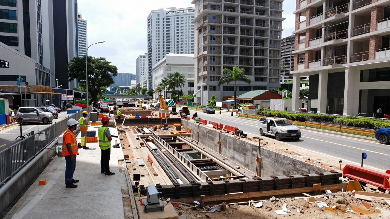
A defensible ERSS AAL framework turns monitoring data into timely, proportionate decisions. It must be grounded in the design, the site baseline, Singapore’s regulatory setting, and clear responsibilities.
- Establish movement objectives before selecting trigger values.
- Build the baseline risk profile before excavation begins.
- Match instruments and thresholds to each receptor and construction stage.
- Link alert, action, and limit levels to specific responses.
- Keep decisions auditable across Project Engineers, Risk Managers, QPs, and contractors.
Establish the purpose and basis of an ERSS AAL framework
Alert, Action, and Limit (AAL) levels are not simply three numbers placed beside a monitoring graph. They form a controlled decision framework for an Earth Retaining Stabilising System (ERSS), connecting predicted behaviour with what the project team must do when site observations depart from expectations. A good framework is established before excavation and reviewed as the works develop. It should also sit comfortably within the applicable design, regulatory, and contractual requirements.
Define ERSS performance objectives and acceptable movement
The first task is to state what the ERSS must achieve. That normally includes stability of the retained ground and support system, control of wall deflection, limitation of ground settlement, management of groundwater effects, and protection of nearby buildings and infrastructure. Acceptable movement is therefore a project-specific engineering judgement rather than a universal figure.
Singapore guidance in the project knowledge base indicates that typical allowable ground settlement beside excavations may range from 10 mm to 25 mm, depending on the sensitivity of nearby structures and utilities. That range is a useful starting reference, not an automatic acceptance criterion. A sensitive utility, an older masonry building, and an open road may require different performance objectives even when they are equally close to the excavation.
Distinguish alert, action, and limit levels
The three levels should describe increasing concern and increasing management response. An alert level is an early warning that warrants verification and closer observation. An action level indicates that the engineering team must assess the cause and implement a defined control or mitigation. A limit level indicates that the observed condition has reached an unacceptable boundary, requiring urgent protective measures and potentially a pause in the affected work.
The levels should apply not only to absolute displacement but also to movement rate, acceleration, differential movement, pore-pressure change, and a combination of indicators. A trigger without a response is incomplete: each threshold should have an owner, a response time, a checking process, and a record of the decision taken.
Identify regulatory, contractual, and design requirements
The AAL framework should be reconciled with the ERSS design basis, method statements, inspection and test plans, authority conditions, and project contract. The knowledge base identifies SS EN 1997-1, or Eurocode 7, as the basis for ERSS limit-state design, including checks for overall stability, structural failure, hydraulic failure, and excessive deformation. The design predictions and monitoring plan should therefore speak the same technical language.
Regulatory coordination may involve BCA, LTA, PUB, SCDF, NEA, or other agencies depending on the site and the affected assets. Where railway assets are nearby, the stated monitoring standards include different movement limits for tracks, tunnels, and station boxes, together with real-time monitoring and SMS or email alerts. Those requirements must be captured explicitly rather than assumed to be covered by a general site alarm.
Account for Singapore’s dense urban context and sensitive receptors
Urban Singapore leaves little room for uncontrolled ground response. Deep excavations may sit beside occupied buildings, live roads, buried services, drainage infrastructure, and underground transport structures, while groundwater and variable soil conditions add uncertainty. The ERSS must control not only collapse risk but also the smaller movements that can damage finishes, distort structures, interrupt utilities, or affect public confidence.
AAL design should consequently distinguish receptors by consequence and vulnerability. It should also consider access for inspection, public interfaces, rainfall, dewatering, excavation sequence, and the practical time needed to respond. A threshold that looks reasonable in a calculation may be unsuitable if the team cannot verify the reading or mobilise mitigation before the next excavation stage.
Build the baseline risk profile before excavation
The baseline risk profile is the reference against which construction behaviour is judged. It combines the ground model, ERSS design, surrounding assets, construction sequence, and pre-existing conditions. Without it, the team may mistake an old crack for construction damage or miss a meaningful change because the monitoring network started too late.
The baseline should be prepared collaboratively by the design and construction teams, then updated when new information changes the risk picture. Early involvement is also consistent with the approach described for Qualified Person Supervision, which includes pre-construction constructability reviews, site challenge identification, and supervision plan development.
Review ground investigation and geotechnical design data
Begin with the factual basis of the ground model: borehole logs, in-situ testing, laboratory results, groundwater observations, geological interpretation, and the parameters used in the ERSS calculations. The knowledge base describes boreholes at approximately 15–30 m spacing, together with SPT, CPT, pressuremeter testing, laboratory testing, and groundwater monitoring as typical components of investigation for deep excavation projects.
The review should look for spatial variability, weak layers, fill, interfaces, artesian or perched groundwater, and uncertainty in parameter selection. It should then compare predicted wall deflections, settlements, pore pressures, and structural forces with the planned monitoring points. Any important assumption should have a field observation or inspection that can test it during construction.
Map adjacent buildings, utilities, roads, and underground structures
A receptor map should show horizontal and vertical separation from the excavation, foundation type and depth, condition, use, structural form, and consequence of damage. For utilities, the team should verify location, depth, material, condition, operational criticality, and ownership. The knowledge base identifies electromagnetic locating, ground-penetrating radar, acoustic methods, CCTV inspection, pressure testing, and coordination with utility agencies as relevant assessment activities.
The map should distinguish verified information from inferred information. It should also mark access constraints, vulnerable interfaces, monitoring points, protection zones, and locations where a small movement could have a disproportionate consequence. This makes the later threshold-setting exercise more transparent and helps the contractor plan work around the most sensitive areas.
Identify excavation stages and critical construction activities
AAL values should be reviewed against the sequence, not treated as static values for the whole project. Critical activities may include wall installation, excavation lifts, strutting or anchoring, dewatering, base preparation, removal of temporary supports, heavy plant movement, adjacent piling, and transfer to permanent works. Each activity can produce a different combination of movement and groundwater response.
The stage register should identify the expected behaviour, monitoring needed before the activity, hold points, and the person authorised to release the next step. It should also account for temporary conditions of permanent structures, since temporary works can impose loads on partially completed permanent works and cast-in items may need to accommodate both temporary and permanent load conditions.
Record pre-construction conditions and establish baseline readings
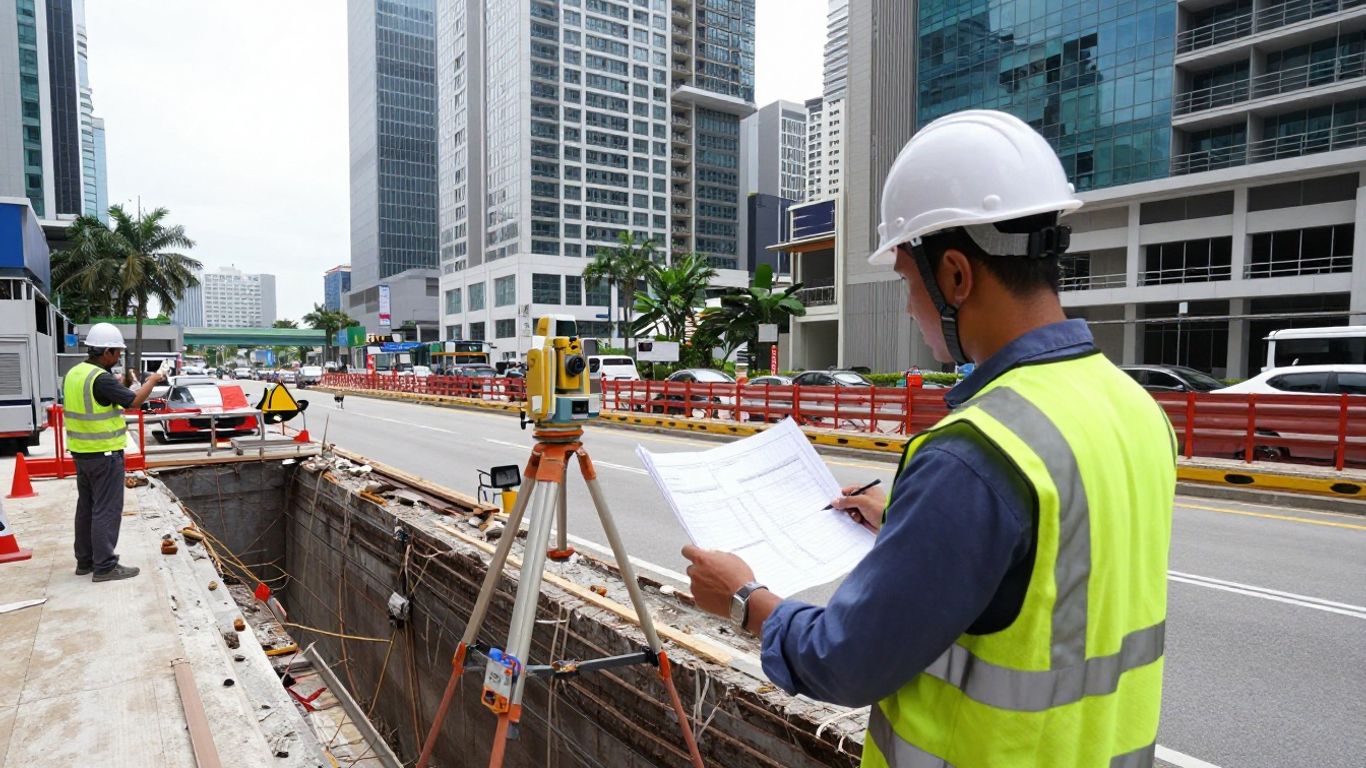
Before excavation, inspect and photograph nearby buildings, roads, pavements, drains, visible utilities, retaining structures, and other relevant assets. Record existing cracks, settlement, leakage, distortion, vibration-sensitive uses, and operational constraints. The survey should be sufficiently detailed to support a fair comparison after work begins, with agreed procedures for resolving disputed pre-existing damage.
Baseline readings should run long enough to identify normal instrument variation and environmental effects. The team should confirm sensor coordinates, datum, calibration, communication links, naming conventions, and data ownership. A short period of stable readings is more valuable than a large set of unverified measurements collected without a clear reference.
Select monitoring parameters and instrumentation
Instrumentation should answer a defined engineering question. The question may be whether the wall is deflecting as predicted, whether drawdown is affecting neighbouring ground, whether a building is responding differentially, or whether a utility is experiencing strain or distortion. Selecting devices by habit can create a busy dashboard without producing useful evidence.
The monitoring plan should state the parameter, instrument, location, frequency, accuracy, trigger values, responsible reader, and action after an abnormal result. It should also explain how manual observations and instrument readings will be reconciled when they appear inconsistent.
Measure wall deflection, ground settlement, and lateral movement
Inclinometers or comparable systems can indicate the shape and change of wall deflection with depth, while settlement points, precise levelling, survey prisms, and ground monitoring arrays can show surface response. The chosen arrangement should reveal both the magnitude and spatial pattern of movement. A single point can miss a developing trough or a localised bulge.
Measurements should be tied to excavation stages and support installation. Wall response before and after a strut is installed may be more informative than a weekly average. Survey teams should also confirm that reference points remain stable; a moving reference can make a well-behaved wall appear to be moving unexpectedly.
Monitor groundwater, piezometric pressure, and drawdown
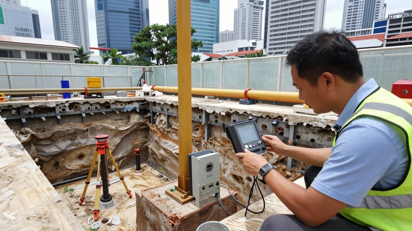
Piezometers and water-level instruments help distinguish structural movement from hydraulic response. A rise in pore pressure may reduce effective stress or increase loading, while excessive drawdown can cause consolidation and settlement outside the excavation. The interpretation must consider rainfall, pumping rates, recharge, tidal effects where relevant, and the permeability of the soil layers.
The monitoring arrangement should cover the excavation and the sensitive areas outside it. Readings should be compared with the dewatering design and with observations from nearby drains, basements, and utilities where access is available. A groundwater alarm is most useful when it prompts a check of pumps, cut-off performance, filters, discharge routes, and nearby settlement data.
Track building, road, utility, and structural response
A receptor-specific programme may include building settlement and tilt points, crack gauges, vibration sensors, road settlement markers, utility movement points, structural strain gauges, or visual inspections. The right parameter depends on the failure or serviceability mode being managed. For example, total settlement may be less informative than differential settlement or angular distortion for a rigid structure.
Readings should be interpreted alongside condition surveys and reports from occupants, road operators, utility owners, and maintenance teams. A change in a building’s monitoring point may be insignificant in isolation but meaningful when it coincides with a new crack, a change in road level, or a pumping adjustment.
Match instruments to soil conditions, excavation depth, and risk exposure
Instrument selection should reflect the ground model, depth and geometry of excavation, ERSS type, groundwater regime, nearby assets, and the speed at which a harmful change could develop. Deep or highly consequential excavations may require automated systems for continuous or near-real-time review, supported by manual checks and independent survey observations.
The design should include redundancy at critical locations and protection against construction damage. It should also define what happens when an instrument is inaccessible, flooded, struck, out of calibration, or disconnected. A replacement reading is not automatically equivalent to the original; the change in measurement method must be recorded and considered in interpretation.
Set technically defensible AAL thresholds
Thresholds should be derived from the project’s predicted behaviour and the consequence of exceeding it. They are not merely selected by dividing a final allowable movement into three convenient portions. The reasoning should be documented so that a reviewer can understand the assumptions, uncertainties, receptor sensitivity, and response time behind each value.
A practical threshold schedule normally combines absolute values with rates and trends. It should identify whether a trigger applies to a single point, a group of points, a spatial pattern, or a correlated set of measurements. That distinction prevents both overreaction to an isolated bad reading and underreaction to a broad but gradual change.
Use design predictions, empirical data, and observational methods
Start with the ERSS analysis, including predicted wall movement, ground settlement, groundwater response, structural forces, and the sensitivity of the selected parameters to construction assumptions. Compare those predictions with empirical experience from comparable ground and excavation conditions, while recognising that local geology and construction quality can differ significantly.
The observational method then provides a controlled way to refine the response as evidence accumulates. It does not mean waiting for failure. The project must define the anticipated range, the warning signs of departure, the available contingency measures, and the decision authority before excavation reaches the relevant stage.
Apply trigger levels to movements, rates, and trends
An absolute displacement trigger can identify how far a point has moved, but it may not show how quickly the condition is worsening. Rate triggers capture acceleration, while trend rules can identify sustained movement across several readings. The framework should specify the calculation window, minimum number of valid readings, treatment of missing data, and whether direction changes affect the assessment.
A useful trigger schedule can be organised as follows, provided the values are calibrated to the project rather than copied from another site:
| Level | Typical interpretation | Required management focus | Evidence to review |
|---|---|---|---|
| Alert | Early departure from expected behaviour | Verify reading and increase attention | Instrument status, nearby readings, site activity |
| Action | Material concern requiring engineering control | Investigate cause and implement mitigation | Trends, stage conditions, groundwater, inspection findings |
| Limit | Unacceptable or potentially unsafe condition | Protect people and assets; stop affected work | Immediate site condition, stability, emergency controls |
The table is a decision structure, not a substitute for engineering judgement. A rapidly increasing movement may warrant action before an absolute limit is reached, while a confirmed instrument fault may require technical verification rather than a construction response.
Allow for instrument accuracy, baseline variation, and data uncertainty
Every trigger should be considered against instrument resolution, accuracy, calibration status, survey error, baseline scatter, reference-point stability, and environmental effects. The usable warning margin must be large enough to distinguish a meaningful change from measurement noise. It must also leave enough time for inspection and mitigation.
Where uncertainty is high, the team may use corroborating instruments, manual checks, visual inspections, or conservative temporary limits. A threshold should never be relaxed simply because data are inconvenient. If the quality of evidence is poor, the correct response is to restore confidence in the monitoring system and reassess the risk.
Define location-specific thresholds for structures and infrastructure
Thresholds should reflect the receptor’s condition, structural system, foundation, age, use, and tolerance for movement. Roads, utilities, historic or fragile buildings, and transport infrastructure may each require separate criteria. The knowledge base records railway-related examples including track, tunnel, and station-box movement and distortion limits, illustrating why a generic ground settlement value may be inadequate near critical transport assets.
The threshold register should show the location, parameter, unit, baseline, alert value, action value, limit value, data source, and responsible reviewer. It should also document the basis for any owner or authority requirement that is more stringent than the general ERSS design criterion.
Connect AAL exceedances to practical response actions
An AAL framework becomes operational only when people know what to do after an alarm. The response should be proportionate, time-bound, and technically specific. It should distinguish a confirmed construction-related change from an instrument fault, while recognising that verification itself may require urgent controls where movement is rapid.
Response plans should be rehearsed for the most credible scenarios, including wall movement, unexpected settlement, groundwater drawdown, support distress, utility damage, and loss of monitoring. The contractor’s safety responsibilities remain intact, while the engineering and risk teams provide oversight, assessment, and escalation within their roles.
Specify immediate checks for alert-level readings
An alert-level reading should prompt a defined first check rather than an informal discussion. The reader should confirm the timestamp, instrument identity, calibration and communication status, reference datum, recent construction activity, and whether adjacent instruments show a similar change. Site personnel should inspect the relevant area for cracking, leakage, support distress, settlement, vibration, or water ingress.
The result should be logged even when the reading proves erroneous. If the change is confirmed, the team may increase reading frequency, restrict a nearby activity, notify the responsible engineer, and compare the observation with the stage-specific prediction. The objective is to create time for a sound decision before the condition reaches action level.
Define engineering reviews and mitigation at action level
At action level, the Project Engineer and relevant QP should review the monitoring trend, construction sequence, groundwater conditions, ERSS condition, and the assumptions used in design. The review should identify the likely mechanism and state whether the current work can continue under controls. It should also record who approved the mitigation and when its effectiveness will be checked.
Possible controls may include changing the excavation sequence, installing or preloading support, reducing the rate of excavation, adjusting dewatering, improving drainage or cut-off measures, backfilling locally, restricting plant loading, or protecting an affected utility. The selected measure must be compatible with the design and verified after implementation.
Establish stop-work and emergency measures at limit level
A limit-level condition requires immediate protection of people and assets. The response may include stopping the affected activity, establishing an exclusion zone, stabilising or supporting the excavation, isolating a damaged service, controlling water ingress, arranging emergency inspection, and notifying the relevant authority or asset owner. The method statement should identify who can order the stop and who can authorise restart.
Restart should follow a documented technical assessment, not a return to work simply because readings have stabilised for one interval. The team should establish the cause, confirm adequate temporary or permanent stability, check the monitoring system, and agree revised controls and thresholds before resuming the activity.
Include escalation procedures for unexpected or rapidly increasing movement
A rapidly increasing trend can be more serious than a slow movement that has reached a similar absolute value. Escalation procedures should therefore cover rate, acceleration, spatial correlation, multiple simultaneous alarms, loss of groundwater control, sudden support deformation, and any condition that cannot be explained promptly. They should include contact details, response times, backup decision-makers, and authority communication routes.
The escalation path should not depend on one person being available. A clear call tree, current drawings, accessible monitoring data, and pre-agreed emergency resources reduce delay. A project that has planned these details can respond to uncertainty without improvising its governance at the worst possible moment.
Manage monitoring data and decision-making on site
Monitoring data should be treated as engineering evidence, not as an automatic verdict. The project needs a process that preserves raw readings, validates them, identifies alarms, interprets trends, and records decisions. That process should work during normal construction and during periods of heavy rain, equipment failure, shift changes, or rapid excavation.
The data workflow should be agreed before mobilisation. It should connect the instrumentation specialist, site supervisors, Project Engineer, QP, Risk Manager, contractor, and asset owners without creating multiple conflicting versions of the same record.
Establish reading frequency and automated monitoring requirements
Reading frequency should reflect the risk, construction stage, movement rate, and time available for intervention. Manual readings may be sufficient for stable, low-consequence parameters, while automated monitoring is appropriate where movement can develop quickly or where access is difficult. Frequency should increase before and during critical activities, then reduce only after the responsible engineer confirms that the risk has reduced.
Automated systems should specify sampling intervals, transmission arrangements, alarm recipients, backup power, data storage, and failure notification. Automation improves speed but does not remove the need for independent checks. A sensor can transmit a precise-looking value that is technically wrong if installation, calibration, or reference control has failed.
Set data validation, quality control, and alarm protocols
Validation should check range, continuity, timestamp, instrument health, calibration, duplicate readings, reference stability, and consistency with nearby points. Alarm protocols should classify confirmed alarms, suspected instrument faults, communication failures, and invalid data separately. This prevents alarm fatigue while ensuring that a missing signal is not mistaken for a safe condition.
The team should define who reviews alarms, how quickly they are acknowledged, how a reading is verified, and how the outcome is closed. Changes to instrument location, software settings, trigger values, or data processing should be approved and recorded. Quality control is part of the safety system, not an administrative task added after the engineering work.
Use trend analysis and stage-by-stage interpretation
A monitoring plot is most useful when it is read alongside excavation depth, support installation, pumping, rainfall, and other site events. Stage-by-stage analysis can reveal whether behaviour is within the predicted envelope or whether a particular operation is causing an unexpected response. Comparing isolated daily values without context often produces either false reassurance or unnecessary alarm.
Interpretation should consider movement direction, differential response, lag effects, rate, and relationships between parameters. For example, settlement outside the wall together with falling piezometric levels may point toward drawdown-related consolidation, while wall deflection with stable groundwater may suggest a support or sequencing issue. These are hypotheses to test, not conclusions to automate.
Maintain auditable records, reports, and authority communications
The record should preserve approved drawings, design calculations, baseline surveys, calibration certificates, raw and processed data, alarm logs, inspection findings, meeting minutes, technical reviews, mitigation records, and restart approvals. Reports should identify the monitoring period, construction stage, exceptions, actions, and outstanding risks in language that can be understood by both engineers and managers.
Authority and stakeholder communications should be factual, timely, and consistent with the technical record. Where an agency or asset owner has specified reporting or notification requirements, those should be included in the project procedure. A clear audit trail protects the public, supports engineering learning, and demonstrates that decisions were made on evidence rather than hindsight.
Clarify responsibilities among Project Engineers, Risk Managers, and QPs
AAL management crosses design, construction, monitoring, safety, and stakeholder communication. Ambiguous responsibility is itself a project risk, particularly when an alarm arrives outside normal working hours or when the contractor and designer interpret a trend differently. The project organisation should therefore assign duties, authority, response times, and escalation routes before excavation begins.
The focus keyword, Project Engineers, Risk Managers, QPs, describes a collaboration rather than three isolated functions. The contractor retains primary responsibility for workplace safety under Singapore’s Workplace Safety and Health framework, while the wider professional team supports compliance monitoring, technical review, and timely risk control.
Assign monitoring and response duties across the project team
The Project Engineer typically coordinates the technical interpretation of the monitoring plan with construction sequence and method statements. The contractor and site supervisors are responsible for carrying out work safely, protecting instruments, observing site conditions, and implementing instructed controls. The instrumentation specialist manages installation, calibration, reading quality, and system performance within the agreed scope.
Responsibilities should be stated in a matrix that covers routine readings, alarm acknowledgement, verification, engineering review, mitigation, stop-work authority, authority notification, and restart approval. The matrix should name individuals or roles, provide alternates, and reflect the actual project organisation rather than an idealised chart.
Define the QP’s role in design review, technical assessment, and certification
The QP should review the relevant design basis, monitoring strategy, construction sequence, and technical evidence within the scope of the appointment and applicable requirements. When an AAL is exceeded, the QP’s assessment should address the engineering mechanism, adequacy of the ERSS and temporary condition, implications for adjacent assets, and whether proposed mitigation is technically acceptable.
Certification is not a replacement for continuous site control. It depends on accurate information, proper supervision, inspection, and timely communication from the project team. For projects requiring independent review, the team should also identify whether an Accredited Checker or geotechnical review is required and coordinate that process early.
Coordinate the Project Engineer, Resident Engineer, contractor, and instrumentation specialist
The Resident Engineer and site supervision team provide the practical connection between approved documents and work on site. They should know the current AAL schedule, hold points, inspection requirements, and communication route for abnormal conditions. The contractor should not be expected to infer a response from a dashboard without a method statement or instruction that explains the required control.
A short, regular coordination meeting can review recent trends, upcoming critical activities, instrument health, open actions, and changes to risk. The team should use one controlled set of drawings and thresholds. When field conditions differ from the design assumptions, the difference should be escalated rather than resolved informally at the workface.
Involve Risk Managers in risk registers, contingency planning, and stakeholder communication
Risk Managers should maintain the project risk register so that AAL exceedances, instrument failures, third-party concerns, and contingency measures remain visible beyond the engineering team. Each significant risk should have a named owner, likelihood and consequence assessment, mitigation, contingency response, and review date. This complements the technical trigger schedule without replacing it.
They can also coordinate stakeholder communication with building owners, utility agencies, transport operators, authorities, and the client. Communication should be proportionate and technically accurate, with clear statements of what has been observed, what is being checked, what controls are in place, and when the next update will be issued. Aman Engineering Consultancy’s documented QPS approach similarly places emphasis on independent expertise, quality assurance, compliance verification, and technical support; those principles are useful when structuring the project’s professional interfaces.
Conclusion
A defensible ERSS AAL framework begins with the design intent and baseline condition, then follows the excavation through instruments, thresholds, response actions, data controls, and accountable decision-making. In Singapore’s dense urban setting, the value of the framework lies in the connection between these parts: Project Engineers, Risk Managers, QPs, contractors, and specialists must be able to act on the same evidence at the right time.
Frequently Asked Questions
What do Alert, Action, and Limit levels mean in ERSS monitoring?
Alert indicates an early warning requiring verification, Action calls for engineering assessment and control, and Limit indicates an unacceptable condition requiring urgent protection and potentially a stop to affected work.
Should AAL thresholds be the same across an entire excavation?
No. Thresholds should reflect the receptor, soil and groundwater conditions, ERSS configuration, construction stage, measurement uncertainty, and consequence of movement at each location.
Which parameters should an ERSS monitoring plan include?
Common parameters include wall deflection, ground settlement, lateral movement, groundwater level, piezometric pressure, drawdown, building movement, road response, utility response, vibration, and structural distortion where relevant.
How is a baseline established before excavation?
A baseline combines condition surveys, photographs, verified asset information, ground and groundwater data, instrument calibration, stable reference points, and a sufficient period of pre-construction readings.
What should happen after an alert-level reading?
The team should verify the instrument and datum, check nearby readings and current construction activity, inspect the affected area, record the finding, and increase monitoring or escalate if the change is confirmed.
When should work stop because of monitoring results?
Work should stop when a limit condition or rapidly worsening and unexplained movement creates an unacceptable risk, or when the approved response procedure directs a pause while stability and protective measures are assessed.
Who should approve changes to AAL thresholds?
Changes should be reviewed and approved by the designated engineering authority, including the relevant QP where applicable, with the basis, affected locations, effective date, communication, and updated monitoring records documented.