

Key Takeaways
A defensible hillside excavation submission connects the ground model, temporary works design, authority requirements, and construction controls from the beginning.
- Define the temporary and permanent works interfaces before design responsibility becomes unclear.
- Investigate soil, rock, groundwater, drainage, adjacent assets, and existing utilities proportionately to risk.
- Verify soil nailing against local and global failure modes, construction stages, and movement limits.
- Submit coordinated calculations, drawings, specifications, permits, and monitoring requirements as one controlled package.
- Carry approval conditions into site inspections, field changes, testing, monitoring, and closeout records.
1. Establish the excavation’s scope, risks, and submission pathway
A hillside excavation is both a geotechnical problem and a controlled administrative process. The design must explain what will be supported, for how long, under which construction stages, and by whom. For Civil Engineers, Infrastructure Designers, that early definition prevents a temporary slope detail from becoming disconnected from permanent foundations, drainage, access, or neighbouring property obligations. It also gives the submission a clear route through the relevant authority process.
Define temporary works, permanent works, and design responsibility
Start with a written scope matrix that separates excavation support, soil nails, shotcrete, drainage, access platforms, protection works, and any permanent retaining or foundation elements. Temporary works may support construction only, but they can still impose loads on partially completed permanent structures. Cast-in items such as anchors, brackets, or embedments therefore need to be checked for both temporary and permanent load conditions.
Name the responsible professional for each design package and state who will review contractor-proposed alternatives. The geotechnical designer may establish soil parameters and stability checks, while the structural designer details facing reinforcement and connections. Where responsibilities overlap, the submission should identify the interface rather than assume that one discipline owns it by default.
Identify hillside hazards, adjacent assets, and public exposure
Walk the site and its perimeter before settling on a support concept. Record slope geometry, loose material, rock outcrops, trees, walls, buildings, roads, footpaths, overhead lines, buried services, and any public route that could be affected by movement or falling debris. A survey should be tied to reliable control points and should capture neighbouring levels, not only the proposed excavation footprint.
Risk is shaped by consequence as much as by excavation depth. A modest cut beside a brittle masonry wall or a busy road may deserve more conservative movement limits than a deeper excavation in an isolated area. The risk register should also address rainfall, uncontrolled surface water, construction vibration, plant loading, unauthorised access, and emergency access for response teams.
ASCE technical resources can provide useful professional context for civil engineering practice, but the project team must still identify the requirements of the actual approving jurisdiction and site.
Confirm the governing jurisdiction, codes, and approving authorities
Confirm the land-use authority, building regulator, drainage agency, road or transport authority, utility owners, and environmental regulator before drawings are finalised. In Singapore, a deep excavation may involve Building and Construction Authority requirements, temporary works submissions, earth control measures, and additional protection requirements near transport infrastructure. International projects may instead require local adoption of ACI, BS, SS, or Eurocode provisions, so the governing edition and departures should be recorded explicitly.
The submission register should state which documents are required, who endorses them, the review sequence, and whether separate permits are needed for earthworks, traffic control, drainage, erosion control, demolition, or utility works. Do not rely on a familiar portal or a previous project. A correct design sent through the wrong pathway can still be rejected.
Set submission milestones around excavation sequencing
Submission dates should follow the physical work sequence rather than sit only on a master programme. The authority needs enough information to understand the first cut, the first support installation, temporary drainage, access arrangements, and the controls that prevent an unsupported face from being left open. Later stages should not depend on an approval that has not yet been obtained.
A practical programme includes design freeze, investigation completion, independent check, pre-consultation, first submission, response period, resubmission, permit release, pre-start inspection, and staged hold points. The project manager should also allow time for revised surveys or supplementary investigation if review comments reveal a gap in the ground model.
2. Build the geotechnical basis for a defensible design
Soil nailing is only as credible as the ground model behind it. A submission should show how field observations, testing, groundwater information, slope geometry, and construction assumptions were converted into design parameters. It should also make uncertainty visible; pretending that a variable hillside is uniform weakens the engineering argument. The investigation should be proportionate to the risk, but never so narrow that it misses the controlling layer or water pathway.
Plan site investigations for soil, rock, groundwater, and existing conditions
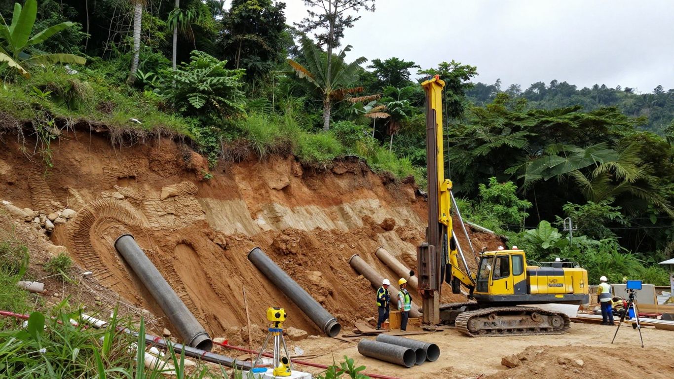
Plan boreholes, trial pits, rock cores, in-situ tests, laboratory tests, and groundwater monitoring around the proposed excavation and the likely failure mechanisms. The programme should identify soil stratification, fill, weathered rock, discontinuities, weak seams, buried obstructions, and the elevation of competent material. Existing retaining walls, foundations, drains, pavements, and utilities also need investigation because they can alter loading and seepage.
For deep excavation work in Singapore, comprehensive site investigation commonly includes boreholes, SPT or other in-situ testing, laboratory testing, and groundwater monitoring. The spacing and depth should be justified against excavation geometry and risk, rather than applied mechanically. Where access is limited, the designer should state what cannot be confirmed and how construction observations or additional probing will address the gap.
Interpret borehole, laboratory, and in-situ testing data
Test results should be interpreted as a spatially variable dataset, not a collection of isolated numbers. Correlate SPT, CPT, pressuremeter, shear strength, unit weight, permeability, rock quality, and index properties with the geological profile. Distinguish measured values from correlations and then select characteristic parameters with a clear explanation of conservatism.
A concise parameter schedule helps reviewers follow the design basis. It should show the adopted value, source, depth or stratum, design role, and any sensitivity range. For example, a lower-bound shear strength may govern local nail bond, while a different stiffness range controls predicted deformation. This separation avoids using one convenient parameter for every check.
| Design input | Primary evidence | Typical design use | Review point |
|---|---|---|---|
| Shear strength | Laboratory and in-situ testing | Global and local stability | Confirm characteristic selection |
| Unit weight | Laboratory data and field description | Earth pressures and surcharge effects | Check saturated condition |
| Permeability | Laboratory testing and observations | Seepage and drainage design | Assess seasonal variation |
| Nail bond strength | Pullout testing and correlations | Nail length and bond zone | Define acceptance criteria |
| Groundwater level | Standpipes, piezometers, and site records | Hydrostatic and seepage checks | Record monitoring period |
The schedule is not a substitute for engineering judgement. It gives the checker a traceable route from evidence to calculation and makes it easier to revise the design when new information arrives.
Assess rainfall, surface runoff, seepage, and seasonal groundwater changes
Hillside water can arrive from above, through the soil, or from a perched layer hidden behind a relatively low-permeability stratum. Map catchments and overland flow paths, then show how temporary drains, berms, sumps, cutoff measures, or protected discharge points will function during each excavation stage. Surface water controls should be integrated with erosion and sediment measures rather than treated as an afterthought.
Use observed groundwater levels alongside rainfall records and plausible wet-season conditions. Check whether seepage can reduce effective stress, soften a face, erode exposed soil, or create uplift behind facing. In Singapore, intense rainfall makes temporary drainage and water accumulation particularly relevant to construction-stage stability, even where the long-term groundwater level appears manageable.
Document geotechnical uncertainties and required design assumptions
The report should distinguish confirmed conditions, interpreted conditions, and assumptions requiring field verification. State the limits of the geological model, the assumed groundwater envelope, the expected variability of nail bond strata, and the response if the excavation exposes weaker or wetter material than predicted. A reviewer can work with uncertainty when it is named and controlled.
Useful controls include observational hold points, probe drilling, trial nails, verification pullout tests, survey monitoring, and a requirement for the geotechnical engineer to inspect changed ground. Clear assumptions protect design intent by linking the calculation to an action in the field. Without that link, a technically correct model may be applied to the wrong ground.
3. Select and verify the slope stabilisation system
The stabilisation system should reflect ground competence, groundwater, available working space, deformation tolerance, access, and the planned excavation sequence. Soil nailing can suit temporary slopes in competent ground, where passive inclusions and a facing work with the soil mass. It is not a universal answer, and the submission should explain why the selected system is appropriate beside the particular assets and exposures on site.
Compare soil nailing with anchors, retaining walls, and other temporary systems
Compare soil nails with ground anchors, sheet piles, contiguous or secant bored piles, diaphragm walls, braced systems, and battered or benched excavation where those options are feasible. Soil nails generally rely on progressive installation as excavation proceeds, whereas prestressed anchors provide active support and may require legal access beyond the site boundary. A wall system may control movement or groundwater more effectively, but can demand larger plant, greater cost, or different permits.
The comparison should cover constructability as well as calculated resistance. Consider drilling access, obstructions, vibration, noise, spoil handling, drainage, property lines, fire and emergency access, removal obligations, and the interface with permanent works. The selected system should be supported by a short options appraisal so the authority can see that site constraints were considered.
Establish nail layout, inclination, spacing, length, and bond zones
Nail geometry should be developed from the failure surfaces and the available competent bond zone. Set out the inclination, vertical and horizontal spacing, length, diameter, drilling method, head arrangement, and minimum bonded length. Distinguish the free or unbonded portion from the bond zone where relevant, and show how nails avoid utilities, foundations, property boundaries, and existing reinforcement.
Check whether the proposed layout remains buildable at corners, benches, transitions, and irregular slope sections. Nail lengths should not be selected solely by repeating a typical detail. They must provide adequate resistance beyond credible failure surfaces while allowing for drilling tolerances and variable ground.
Design facing, drainage, shotcrete, mesh, and connection details
Facing transfers local soil pressures and nail head forces while protecting the exposed face from ravelling and weather. Detail shotcrete thickness, reinforcement mesh, bars, bearing plates, nail head connections, construction joints, edge beams, and any permanent finish separately. The drawings should make clear which components are temporary and which remain in the completed works.
Drainage details deserve equal attention. Show weep holes, strip drains, collector pipes, filter layers, outlets, cleanouts, and connections to the site drainage system. Provide measures for blocked outlets and temporary discharge during rain. A facing system that is structurally adequate but traps water behind it is not a complete stabilisation design.
Check global, local, pullout, sliding, overturning, and bearing stability
Verification should cover the whole reinforced soil mass as well as individual nails, facing elements, and support interfaces. Check global rotational or translational failure, local face stability, nail tensile resistance, pullout, connection capacity, sliding, overturning, bearing, hydraulic failure, and excessive deformation. Apply the governing limit-state framework and partial factors required by the jurisdiction; for Singapore ERSS work, the source design basis identifies SS EN 1997-1 and checks at Ultimate and Serviceability Limit States.
The analysis should represent staged excavation and support installation, not only a final geometry. Where geometry is complex or neighbouring structures are sensitive, staged finite-element analysis may help examine soil-structure interaction and deformation. PLAXIS Suite is documented for geotechnical finite-element analysis, including staged construction, groundwater flow, safety analysis, and deformation visualisation; its use must still be supported by suitable parameters and engineering review.
4. Prepare the engineering calculations and technical specifications
Calculations should allow an independent reviewer to reproduce the design logic without searching through drawings or undocumented assumptions. Begin with the construction sequence, then define actions, material properties, groundwater conditions, factors, limit states, and acceptance criteria. Temporary works are often short-lived, but their critical load cases occur while the site is most exposed and least complete.
Define construction-stage load cases and excavation sequences
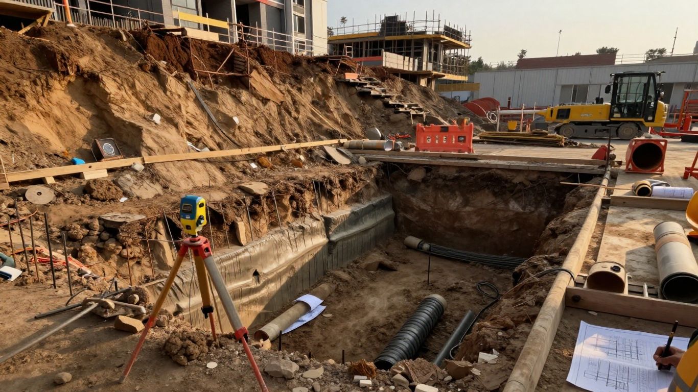
Model the actual sequence: establish controls, divert water, excavate a lift, drill and grout nails, install drainage, construct facing, and proceed to the next bench. Include the condition of an open lift before support is complete and the possibility of a temporary interruption caused by weather, plant failure, or inspection. Each stage should have a defined maximum unsupported height and a release condition for the next cut.
Where temporary works interact with permanent foundations or slabs, analyse the partially completed structure as a temporary condition. Show whether loads are transferred into permanent elements, whether construction traffic can reach the crest, and when temporary supports may be removed. This is where design responsibility and sequencing must meet in one calculation narrative.
Account for surcharge, equipment, traffic, wind, seismic, and hydrostatic effects
Surcharge assumptions should reflect real site use rather than a generic uniform strip. Identify stored materials, cranes, excavators, trucks, traffic lanes, temporary platforms, adjacent foundations, and crowd or public loading. Include wind where exposed screens, formwork, barriers, or temporary structures affect the slope system, and consider seismic actions where the governing code requires them.
Hydrostatic pressure, seepage forces, ponding, and rapid water-level changes can govern a temporary hillside excavation. Rainfall should be considered in both the slope model and the construction method. The specification should require the contractor to keep crest drainage functional and prevent uncontrolled water from reaching an unsupported face.
Specify nail materials, corrosion protection, testing, and acceptance criteria
The specification should identify steel grade, bar or tendon type, grout requirements, centralisers, drilling diameter, grout pressure or method, corrosion protection, plates, nuts, couplers, and facing materials. The required design life determines the corrosion protection approach, particularly where temporary nails may remain beneath permanent works or in aggressive ground.
Testing must be tied to decisions. State proof, verification, and sacrificial test requirements; test locations; loading increments; hold periods; displacement limits; and the response to a failed result. Also specify grout records, drilling logs, installation tolerances, nail identification, and repair procedures for damaged facing or blocked drainage.
Include temporary works design checks and independent review requirements
The package should identify the design check category, checking engineer, review scope, and approval authority within the project team. High-risk excavations, complex support systems, and works beside sensitive assets generally justify a more formal independent review. The reviewer should receive the ground model, calculations, drawings, sequence, monitoring plan, and assumptions together.
STAAD Pro is documented for structural analysis, including three-dimensional modelling, load application, stress and deformation assessment, dynamic analysis, and code checks. It may support structural checks for facing or associated temporary elements where appropriate, but it does not replace geotechnical stability assessment or the professional engineer’s judgement.
5. Assemble drawings and documents for authority submission
A submission succeeds when the documents tell one consistent story. Plans establish location and limits, sections explain geometry and interfaces, calculations justify resistance, and specifications define how the design is to be built and accepted. Inconsistent levels, nail lengths, excavation stages, or drainage routes create avoidable review comments and can become field hazards.
Produce existing-condition, demolition, excavation, and stabilisation plans
Begin with a reliable existing-condition plan showing boundaries, levels, buildings, walls, utilities, roads, vegetation, drainage, and survey control. Add demolition limits only where verified, then show excavation extents, benches, access, temporary fencing, water controls, nail zones, facing, and discharge points. Use clear linework and a legend that distinguishes existing, temporary, proposed, and removed elements.
The plan should also identify sections and details by reference. Reviewers should be able to move from a plan location to the corresponding calculation and section without guessing. If the works are near a public route or neighbouring property, show protection and exclusion measures directly on the plan.
Detail sections, nail profiles, facing reinforcement, and drainage interfaces
Sections should cut through representative and controlling conditions, including crest surcharge, adjacent foundations, groundwater, weak layers, rock transitions, benches, and the toe. Show nail inclination, length, bond zone, head connection, facing thickness, reinforcement, drainage layer, outlet, and final interface with permanent work. A single generic section is rarely enough for a variable hillside.
Profiles and schedules should identify nail marks, spacing, tolerances, test locations, and any changes by elevation. Drainage details should connect logically to the site discharge arrangement and show temporary protection against erosion. Where the nail wall is removed or buried, state the treatment and record requirements.
Add construction notes, hold points, tolerances, and method constraints
Construction notes should turn design assumptions into observable controls. State maximum lift heights, permitted unsupported duration, drilling restrictions, grouting requirements, inspection points, wet-weather limits, face protection, and the need to stop work if ground conditions differ materially. Hold points should occur before covering drainage, before advancing to the next lift, and before loading the crest.
The notes should also define tolerances for nail position, inclination, length, grout volume, facing thickness, reinforcement placement, and drainage outlet levels. These are not decorative details. They tell the contractor and inspector what deviation is acceptable and when the designer must be consulted.
Coordinate civil, structural, geotechnical, survey, utility, and environmental documents
Run a formal interdisciplinary check before submission. Compare survey coordinates with civil plans, utility information with drilling locations, structural details with nail heads and permanent elements, and environmental drawings with drainage outlets and erosion controls. Resolve discrepancies in a controlled revision rather than leaving them for construction.
A document register should identify the current revision, author, checker, date, approval status, and superseded files. Include the method statement, risk assessment, monitoring plan, inspection and test plan, calculations, drawings, specifications, permits, and supporting investigation reports. This integrated package is especially important where several professional endorsements are required.
6. Manage the submission workflow with reviewing authorities
Authority review is easier when the project team understands the reviewer’s concerns before formal submission. The goal is not merely to upload a complete file set, but to make the safety case legible: what is being excavated, what supports it, what could move, how movement will be detected, and what happens if conditions change. Early engagement can expose requirements that are difficult to retrofit after design freeze.
Conduct pre-consultation with the local authority and relevant agencies
Prepare a concise pre-consultation brief with the site plan, excavation depth, slope geometry, adjacent assets, proposed support system, investigation summary, construction sequence, monitoring concept, and list of approvals sought. Ask focused questions about submission pathways, required endorsements, movement criteria, transport or utility protection, erosion control, and inspection expectations.
Record the meeting date, attendees, advice, action owners, and whether the authority’s comments are formal requirements or preliminary guidance. The brief should then be updated and circulated to all designers. That simple record prevents one discipline from designing to an assumption that another agency has already rejected.
Coordinate permits for excavation, erosion control, drainage, utilities, and traffic
Create a permit matrix that follows the work package rather than the consultant discipline. Excavation support may sit beside earth control measures, temporary discharge approval, road occupation, utility permits, demolition consent, equipment permits, and neighbouring-property agreements. Each item needs an applicant, submission date, dependency, expiry or renewal date, and evidence of approval.
Environmental controls should be designed into the same sequence as excavation. Sediment barriers, protected discharge, inspection routines, and severe-weather response should be shown where they operate. Utility owners should receive enough detail to confirm clearance, protection, isolation, or monitoring arrangements before drilling begins.
Define the civil engineer’s, geotechnical engineer’s, contractor’s, and reviewer’s roles
The responsibility matrix should distinguish design, checking, approval, inspection, notification, and emergency decision-making. The civil engineer may coordinate site layout and drainage, the geotechnical engineer may own ground parameters and stability, and the contractor may own means and methods within the approved constraints. None of those roles should be implied only by a signature block.
Set out who can release a hold point, who can approve a field change, who must inspect exposed ground, and who contacts the authority after a trigger exceedance. The matrix should also address temporary works that interface with permanent structures, because a contractor’s sequence can change the loading condition before the permanent designer expects it.
Track document versions, responses, resubmissions, and approval conditions
Use a comment register that reproduces each authority comment, assigns an owner, records the response, identifies the revised document, and notes whether the issue is closed. Keep a separate conditions register for approval obligations that continue into construction, such as monitoring frequency, inspection attendance, reporting, restricted working hours, or required notifications.
Do not overwrite submitted files without preserving the audit trail. A clear transmittal should list every file, revision, status, and change summary. Before resubmission, perform a cross-document check so a revised calculation does not quietly conflict with an unchanged plan or method statement.
7. Link approval conditions to construction control and closeout
Approval is a transition into controlled construction, not the end of design. The approved sequence, monitoring thresholds, hold points, and reporting duties must be visible to supervisors and subcontractors. A strong closeout process begins before the first nail is installed, because records that are not planned tend to disappear during a fast excavation programme.
Sequence excavation, nail installation, facing, drainage, and bench completion
Divide the slope into manageable lifts and define the maximum open face for each stage. Strip and control surface water first, excavate only to the permitted level, inspect the exposed ground, install nails and drainage, place facing, and release the next lift only after the required checks are complete. Bench completion should not obscure outlets, survey points, or access for inspection.
The sequence should address interruptions. If rain prevents drilling or shotcrete, the contractor needs a permitted temporary protection measure rather than an improvised cover. Plant routes and crest loading should be controlled throughout, with changes referred back to the designer when they exceed the approved assumptions.
Establish instrumentation, survey points, inspection routines, and trigger levels
Monitoring should combine instruments with practical visual inspection. Establish survey points on the slope, crest, adjacent assets, and public-side features, then define readings, frequency, baseline period, responsible personnel, and reporting recipients. Where groundwater is a concern, include standpipes or piezometers and correlate readings with rainfall and excavation stages.
Trigger levels should lead to predetermined actions, not merely generate a warning. A staged response may include increased reading frequency, suspension of the next excavation lift, inspection by the geotechnical engineer, temporary propping or drainage, notification of authorities, and evacuation where necessary. The values should be set against sensitivity of nearby assets and the expected construction response.
Manage field changes, unexpected ground conditions, and emergency response
Unexpected conditions include loose fill, cavities, weak seams, artesian water, obstructions, excessive nail grout take, rock discontinuities, or movement beyond the predicted trend. The contractor should stop the affected activity, protect personnel and the public, document the condition, and notify the designated engineers. The revised solution must be checked against the same limit states and approval conditions as the original.
Emergency arrangements should identify access, communications, exclusion zones, temporary drainage, standby materials, and authority contacts. A field change should never be justified only by convenience or production pressure. Record the reason, sketches, photographs, calculations, instructions, approvals, and the exact location so the final record remains intelligible.
Compile test records, as-built drawings, monitoring data, and completion submissions
Closeout records should demonstrate what was installed and how it performed. Assemble drilling and grouting logs, nail test results, material certificates, facing inspection records, drainage inspections, survey data, groundwater readings, nonconformance reports, approved changes, and daily site records. Organise them by location and revision so a future reviewer can trace a nail or drain from drawing to field evidence.
As-built drawings should capture actual nail coordinates, lengths, inclinations, drainage routes, facing limits, permanent interfaces, and any deviations accepted during construction. The completion submission should include monitoring trends, unresolved maintenance duties, inspection recommendations, and authority sign-off where required. This record protects the owner and gives future works a reliable basis.
Conclusion
A temporary hillside excavation becomes defensible when investigation, stabilisation design, submission management, and construction verification are treated as one connected engineering process. Clear responsibility, honest assumptions, coordinated documents, and disciplined monitoring give authorities and project teams confidence that the approved design will remain meaningful in the field.
Frequently Asked Questions
Is soil nailing suitable for every hillside excavation?
No. Suitability depends on soil or rock competence, groundwater, excavation geometry, available access, movement tolerance, adjacent assets, and whether nails can be installed safely beyond likely failure surfaces. Alternatives may be required where the ground is weak, water-bearing, highly variable, or too constrained for drilling.
What information should a geotechnical investigation provide?
It should establish soil and rock stratigraphy, strength, unit weight, stiffness, permeability, groundwater conditions, obstructions, existing foundations, utilities, and relevant geological hazards. The report should also explain variability, testing limitations, characteristic parameters, and assumptions requiring field verification.
Which stability checks are normally expected?
A submission commonly addresses global and local stability, nail tensile resistance, pullout, facing and connection capacity, sliding, overturning, bearing, hydraulic failure, and deformation. The exact checks and factors depend on the governing code, support arrangement, groundwater, construction stage, and sensitivity of nearby assets.
Why must construction sequencing appear in the calculations?
Temporary support systems experience their most critical conditions during partial excavation, before the final system is complete. Sequencing establishes unsupported heights, installation timing, surcharge locations, drainage controls, and the conditions required before the next lift can proceed.
What should monitoring trigger levels do?
Trigger levels should connect measured movement, groundwater, or rainfall conditions to defined actions. Those actions may include more frequent readings, engineering inspection, stopping work, temporary protection, revised analysis, authority notification, or evacuation, depending on the severity and risk.
How are authority comments best managed?
Use a controlled comment register with an owner, response, revised document reference, status, and closure date for every comment. Preserve submitted revisions and maintain a separate conditions register so construction obligations are not lost after approval.
What belongs in the closeout package?
The package should include approved drawings, as-builts, investigation updates, installation and grout records, material certificates, test results, inspection records, monitoring data, field changes, nonconformances, drainage records, and completion or authority submissions. It should also state any ongoing inspection or maintenance requirements.