

Key Takeaways
Deep excavation dewatering is both a geotechnical design problem and an authority-submission exercise. A defensible submission connects the ground model, seepage calculations, environmental controls, and field monitoring into one coherent basis.
- Define excavation stages, groundwater-control objectives, and measurable performance criteria before selecting equipment.
- Build the ground model from investigation data, groundwater observations, and conservative treatment of uncertainty.
- Compare dewatering and seepage-control options against inflow, drawdown, settlement, constructability, and discharge constraints.
- Coordinate permits and technical documents with ERSS, drainage, temporary works, and environmental submissions.
- Use instrumentation and documented field records to verify predictions and support approved changes during construction.
1. Establish the groundwater-control basis for a deep excavation
A dewatering submission should begin with the excavation itself, not with a preferred pump arrangement. The geometry, formation levels, retaining system, and construction sequence determine how water will move and how the surrounding ground may respond. For Site Engineers, Environmental & Geotechnical Consultants, the central task is to turn those project conditions into a clear groundwater-control basis.
Define excavation geometry, formation levels, and construction stages
Record the excavation footprint, final formation, working levels, access ramps, internal slabs, strutting levels, and planned temporary conditions. A staged sequence is essential because groundwater pressures and seepage paths change as soil is removed and support elements are installed. The submission should show when cut-off walls, drains, sumps, wells, anchors, and permanent slabs become active, rather than treating the excavation as a single finished shape.
Temporary and permanent works also need to be considered together. Anchors, brackets, embedments, and other temporary supports may impose loads on partially completed permanent structures, so their conditions should be identified in the design narrative and drawings.
Identify groundwater sources, recharge pathways, and nearby water-sensitive receptors
Groundwater may enter through permeable sand layers, joints in rock, defects at wall joints, utility corridors, or perched zones above less-permeable strata. Recharge can come from rainfall infiltration, leaking services, adjacent drainage channels, tidal interaction, or hydraulic connection to a wider aquifer. Map these pathways alongside neighboring basements, foundations, roads, tunnels, utilities, drains, waterways, and other receptors that could be affected by drawdown or discharge.
A receptor inventory should state why each feature is sensitive and how it will be observed. This makes later monitoring commitments easier to justify and helps distinguish a manageable seepage source from a condition that could cause off-site movement.
Distinguish between dewatering, drawdown control, and seepage mitigation
Dewatering removes or intercepts water so excavation can proceed safely. Drawdown control limits the reduction in groundwater pressure outside the site, often through cut-off walls, staged pumping, recharge, or a combination of measures. Seepage mitigation addresses localized leakage, uplift pressure, piping risk, or water entering through joints and defects; it may involve grouting, waterstops, drainage layers, or repairs rather than broad pumping.
Keeping these objectives separate prevents an authority submission from promising a pump capacity that does not address the actual risk. It also clarifies what will be measured: total inflow, groundwater head, pore pressure, discharge quality, or movement of adjacent ground.
Set performance criteria for excavation stability, base heave, piping, and settlement
Set criteria before the analysis is finalized. They should cover hydraulic gradients, basal uplift, piping, overall stability, wall movement, adjacent settlement, allowable discharge quality, and acceptable groundwater levels at sensitive receptors. In Singapore, ERSS design is generally evaluated under Ultimate and Serviceability Limit States, with movement criteria related to the sensitivity of nearby structures and utilities.
The criteria should be practical enough to trigger action. A predicted value without a corresponding alert level, monitoring frequency, and response is not a complete control measure. Clear acceptance criteria give the designer, contractor, and reviewing authority a shared basis for decisions.
2. Build a reliable ground and groundwater model
Seepage analysis is only as credible as the model behind it. Deep excavations can pass through fill, coastal alluvium, residual soils, weathered rock, and fractured or solution-featured limestone within a short distance. The investigation and interpretation therefore need to capture both vertical layering and lateral variability.
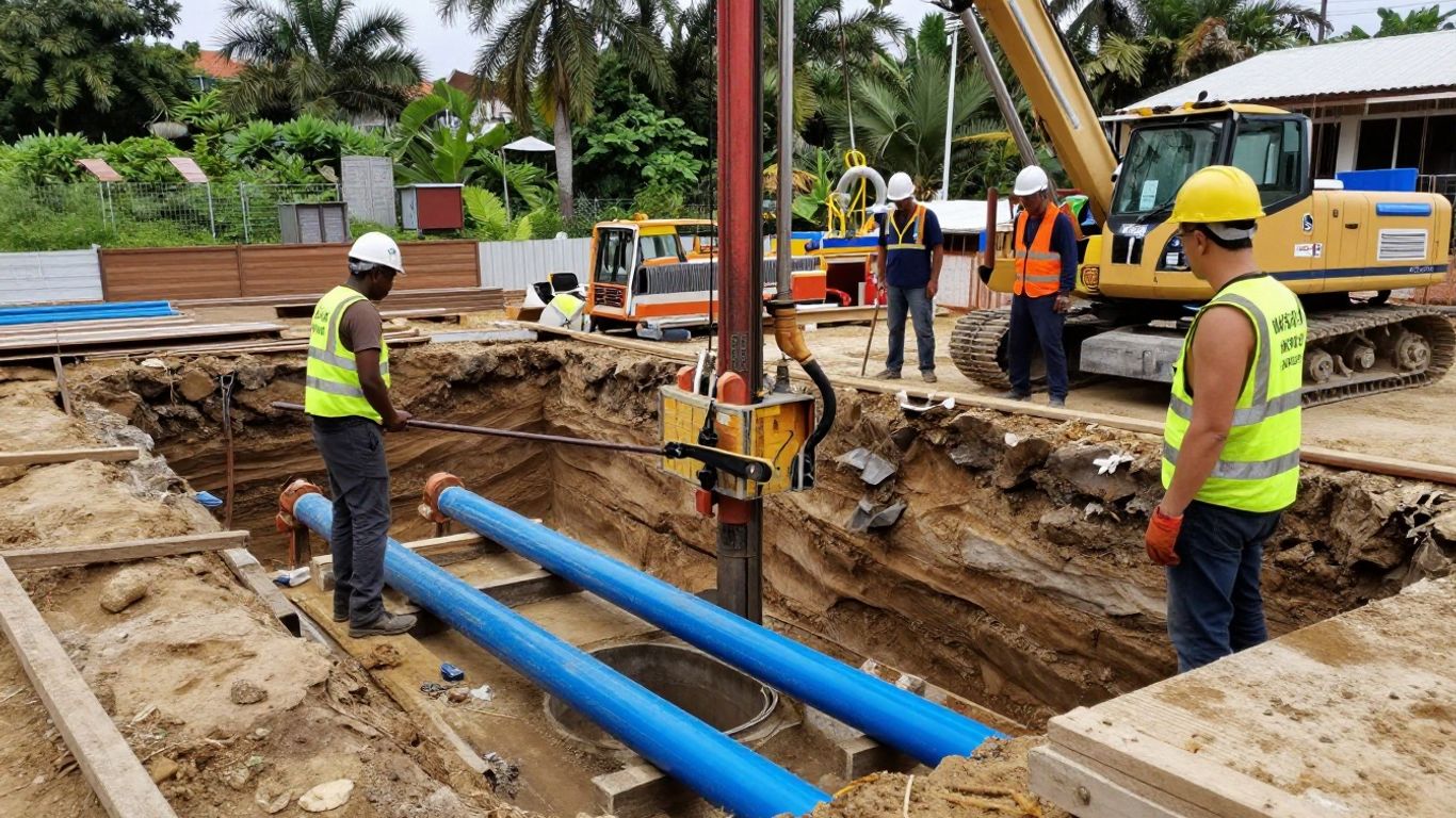
Plan boreholes, in-situ testing, laboratory testing, and groundwater monitoring
Plan investigation locations around the excavation, retaining walls, likely pumping zones, and sensitive receptors rather than relying on a uniform grid alone. Boreholes, SPT, CPT, pressuremeter testing, permeability testing, grain-size analysis, consolidation testing, and strength testing each answer different design questions. Install groundwater instruments early enough to observe baseline conditions and, where possible, record levels through representative wet and dry periods.
Coordinate the investigation with available as-built records and utility information. A broader site characterization approach, such as the one described in CEC geotechnical services, can be useful as a reminder that investigation should support planning, design, and construction—not just a single report.
Characterize coastal alluvium, residual soils, rock, and limestone solution cavities
Coastal alluvium may contain loose sand, soft clay, or interbedded layers with sharply different conductivities. Residual soils can vary over short distances as weathering progresses into rock, while fractured rock may transmit water through preferential joints. Limestone formations require particular caution because solution cavities can create unexpected inflow, localized loss of ground, or difficult drilling conditions.
The model should show where each unit is inferred, how boundaries were selected, and which observations support the interpretation. Do not smooth away an isolated high-permeability layer merely because it is inconvenient for the calculation; explain whether it is real, uncertain, or conservatively represented.
Interpret hydraulic conductivity, permeability anisotropy, and groundwater levels
Hydraulic conductivity should be interpreted from the full evidence set, including field tests, laboratory results, pumping observations, soil fabric, and geological structure. Horizontal and vertical conductivity may differ substantially, particularly in layered alluvium or weathered formations. Groundwater levels should be plotted against time and elevation, with datum, instrument depth, and screened interval clearly recorded.
Where field data are sparse, use parameter ranges rather than a single apparently precise value. The selected values should be tied to the seepage cases, and the report should explain whether they represent average, upper-bound, or deliberately conservative conditions.
Account for seasonal rainfall, tidal influence, perched water, and artesian conditions
A groundwater model should reflect the site’s hydraulic setting, not only the level measured on the investigation date. Rainfall can recharge shallow zones quickly, tides can alter coastal heads, and perched water can sit above an aquitard without reflecting the deeper regional water table. Artesian or confined pressures may remain after excavation begins and can affect base stability even where the visible excavation appears relatively dry.
Use monitoring trends, nearby records where reliable, and field observations to define design cases. If the project is near the coast or reclaimed land, include a clear explanation of how tidal and rainfall conditions were translated into boundary heads or sensitivity scenarios.
Document data gaps and assumptions that require conservative treatment
A good model makes uncertainty visible. List missing boreholes, uncertain stratum contacts, unverified utility leaks, short monitoring records, unknown wall defects, and any assumed recharge or discharge boundary. Then state how each gap affects the analysis and what field observation or contingency measure will reduce the uncertainty during construction.
This is also where the design team should record the limits of numerical precision. A detailed mesh cannot compensate for unsupported soil parameters or an incorrect boundary condition. The submission becomes more credible when its assumptions are explicit and testable.
3. Perform seepage analysis and select a dewatering system
The purpose of seepage analysis is not simply to calculate a pumping rate. It is to compare feasible control measures, identify hydraulic failure modes, estimate off-site effects, and provide values that can be checked in the field. The analysis should remain connected to the excavation sequence and the permit conditions that will govern discharge.
Choose analytical methods, numerical models, and appropriate soil constitutive assumptions
Select the method according to the complexity of the ground and the decision being made. Simplified analytical solutions may help with an early estimate, while finite-element or finite-difference models may be appropriate where staged excavation, anisotropy, structures, or coupled deformation must be considered. Constitutive assumptions should match the available data and the behavior that matters, such as soft-soil consolidation, granular drainage, or rock-fracture flow.
For ground-movement assessment, a model may include Mohr–Coulomb, Hardening Soil, or Soft Soil Creep behavior where justified by testing and calibration. The report should explain why each model was selected and avoid suggesting a level of certainty that the investigation cannot support.
Model excavation stages, retaining walls, cut-off systems, and drainage boundaries
Represent the actual sequence: initial groundwater conditions, wall installation, excavation lifts, support activation, pumping start-up, formation preparation, and permanent slab construction. Retaining walls should be modeled with their hydraulic behavior, including permeability, joints, toe penetration, and any planned cut-off treatment. Drainage boundaries should reflect real sumps, drains, wells, recharge points, rivers, canals, or impermeable limits.
Boundary conditions deserve special attention. An overly close fixed-head boundary can inflate inflow, while an artificially impermeable boundary can conceal regional drawdown. Run a reasonableness check against observed water levels and expected pumping behavior before using the results in a permit submission.
Compare wells, wellpoints, sumps, ejectors, recharge systems, and low-permeability barriers
System selection should follow the hydraulic problem and construction constraints. Wells may suit deeper or more distributed pumping, while wellpoints can provide closer control in suitable shallow permeable layers. Sumps are simple but may be unsuitable where uncontrolled gradients, fines migration, or water-quality risks are significant; ejectors may be considered where the available head and soil conditions support them. Recharge systems and low-permeability barriers can help limit off-site drawdown when pumping alone would create unacceptable effects.
Compare options in a consistent way before recommending one. A compact decision table can keep the technical report focused on performance rather than equipment preference.
| Control option | Useful application | Main review concern | Evidence to submit |
|---|---|---|---|
| Pumping wells | Deeper or distributed aquifers | Regional drawdown and discharge volume | Well layout and pumping cases |
| Wellpoints | Shallow permeable strata | Spacing, vacuum limits, and fines | Section, spacing, and flow estimate |
| Sumps | Localized seepage collection | Erosion, piping, and turbid water | Collection and treatment details |
| Cut-off barriers | Limiting hydraulic connection | Continuity, joints, and toe seepage | Wall details and seepage assumptions |
The preferred system should be linked to trigger levels and standby arrangements. If the analysis predicts a narrow operating margin, a second control measure may be more valuable than a larger nominal pump capacity.
Evaluate inflow rates, drawdown profiles, and discharge-quality requirements
Report expected inflow by stage, not only a single total. Show drawdown contours or receptor-specific groundwater changes, identify the period of maximum pumping, and state whether the values include rainfall, leakage, uncertainty, or a contingency allowance. Pumping rates should be checked against treatment capacity, temporary storage, discharge-route capacity, and the authority’s sampling requirements.
Water quality may vary as excavation proceeds. Suspended solids, turbidity, pH, oil, grease, and potential contamination should be addressed through source control, settlement, filtration, treatment, and sampling. Discharge limits and receiving-water protections must be verified against the applicable authority requirements rather than assumed from a generic method statement.
Test sensitivity to uncertain soil and groundwater parameters
Run sensitivity cases for conductivity, anisotropy, recharge, initial head, wall permeability, cut-off continuity, and pumping efficiency. Include conditions such as a more permeable sand seam, a higher wet-season head, or a partially clogged well. The aim is to identify which uncertainties control inflow and drawdown, then target monitoring and contingency planning accordingly.
Interpret sensitivity results as decision support. If a small parameter change produces a large off-site effect, the permit package should include stronger observational controls and a more conservative operating envelope.
4. Prepare dewatering permits and authority submissions
A technically sound seepage model can still fail review if the submission does not identify responsibilities, discharge controls, or interfaces with other approvals. Treat the permit package as a coordinated set of documents, with consistent project data, drawings, calculations, and method statements. The level of detail should allow a reviewer to understand what will happen, where water will go, and how unexpected behavior will be managed.
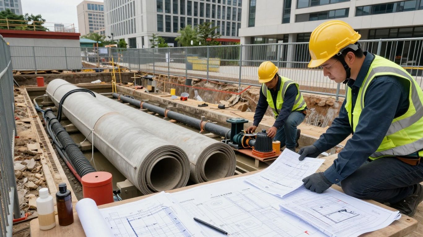
Identify the applicable agencies, permits, approvals, and project responsibilities
Prepare an approval matrix early. Depending on location and scope, the project may involve building, temporary works, drainage, environmental, landowner, transport, utility, or water-agency requirements. In Singapore, deep excavation submissions commonly need coordination with BCA requirements, ERSS design, drainage protection, and any agency responsible for nearby infrastructure.
Assign each document to a named qualified person, consultant, contractor, or owner representative. The matrix should show the submission sequence, dependencies, review periods, required endorsements, and response owner for authority comments. This avoids the common situation where a dewatering method is technically complete but cannot proceed because a related approval is still outstanding.
Assemble the technical report, calculations, drawings, and method statements
The report should explain the design basis, investigation findings, groundwater model, seepage analysis, selected system, operating limits, monitoring plan, discharge controls, and emergency response. Calculations should be traceable to drawings and assumptions. Drawings should show well locations, headers, pumps, treatment units, discharge points, monitoring instruments, access, standby equipment, and interfaces with the ERSS.
The method statement should describe installation, commissioning, staged pumping, inspection, maintenance, shutdown, and reinstatement. It should also explain what happens if the observed flow or groundwater response departs from the design case. Clear cross-references make the package easier to review and reduce contradictory instructions between documents.
Present discharge locations, treatment measures, sampling plans, and monitoring points
Identify every proposed discharge route and its receiving environment. Show treatment stages, bypass arrangements, storage capacity, sampling locations, sample frequency, laboratory responsibilities, and record retention. The plan should distinguish routine monitoring from commissioning tests and from event-based sampling after heavy rainfall, equipment failure, or a change in water appearance.
Environmental controls should be measurable. For earth-control planning, the knowledge base identifies performance standards including turbidity and total suspended solids limits of 50 above background, a pH range of 6.0–9.0, and no visible oil, grease, or floating debris; the applicable project approval should always be checked before adopting those values.
Address environmental impacts on drains, waterways, utilities, and neighboring properties
Discuss how pumping could affect drainage capacity, receiving waters, buried services, adjacent basements, private wells, and property conditions. Include erosion and sediment controls at discharge outlets, protection against scour, and measures to prevent untreated water from bypassing the treatment system. If contamination is possible, state the investigation and treatment pathway rather than treating all groundwater as clean.
The submission should also explain communication arrangements for affected parties. Photographic condition surveys, baseline readings, complaint channels, and escalation contacts can provide useful evidence if water levels or movement change during the works.
Coordinate dewatering documents with ERSS, temporary works, drainage, and construction submissions
Dewatering affects wall loads, basal stability, ground movement, access, sequencing, and sometimes the permanent structure. Coordinate the package with ERSS calculations, temporary works drawings, drainage plans, excavation method statements, environmental management plans, and permanent works interfaces. Any discrepancy in excavation level, wall toe, pump location, or construction stage can materially change the seepage result.
A coordinated submission also supports review by different disciplines. Aman Engineering Consultancy’s globally oriented practice is relevant where engineering endorsement must align with Singapore, UK, UAE, Malaysian, or international standards, but the submission should still identify the precise code and authority basis for the project at hand.
5. Demonstrate protection of adjacent structures and the environment
Protection is demonstrated through predicted effects, defined limits, instrumentation, and response actions. It is not enough to state that drawdown will be controlled; the submission must show where groundwater may change, how much movement is acceptable, and what will happen if readings exceed expectations. The same principle applies to discharge quality and stormwater protection.
Assess drawdown-induced settlement and ground movement beyond the excavation
Lowering pore pressures can cause consolidation, effective-stress changes, or migration of fines outside the excavation. Assess settlement and lateral movement using the ground model, wall behavior, pumping cases, and construction stages. Consider both direct wall deflection and wider drawdown-induced effects, especially where compressible alluvium or loose fill is present.
Report predicted movement at relevant receptors and compare it with project-specific criteria. Where results approach a limit, refine the analysis and consider reducing pumping, improving cut-off continuity, staging the excavation, or introducing recharge before construction begins.
Check effects on neighboring foundations, roads, utilities, basements, and heritage structures
Review foundation type, depth, condition, sensitivity, and distance from the excavation. Utilities require particular care because settlement or leakage can create a feedback loop: a damaged service may add recharge, while movement may damage the service further. Roads, basements, and heritage structures should be assessed using condition surveys and monitoring points selected for their actual structural behavior.
The assessment should document assumptions about buried geometry and foundation support. Where records are incomplete, use targeted exposure, utility detection, CCTV, or supplementary investigation rather than relying on an optimistic interpretation.
Define trigger levels, alert levels, and stop-work criteria for instrumentation
Instrumentation limits should be tied to predicted behavior and response time. Establish baseline readings, alert levels, action levels, and stop-work criteria for piezometers, settlement markers, inclinometers, structural survey points, flow meters, and discharge-quality measurements. State who reviews each result and how quickly the response must occur.
A practical response sequence usually includes checking the instrument, confirming the trend with an independent reading, reviewing pumping and rainfall conditions, and implementing the approved contingency. The trigger system should be understood by the site team before excavation starts, not introduced after an exceedance.
Incorporate erosion, sediment, turbidity, contamination, and water-quality controls
Water discharged from an excavation can carry fine sediment, dissolved constituents, oil, or construction debris. Use protected conveyance, energy dissipation, settlement, filtration, treatment, and routine inspection as appropriate to the risk. Keep clean stormwater separate from process water where feasible, and maintain emergency storage so a failed treatment unit does not become an uncontrolled discharge.
Monitoring records should identify sample location, time, weather, pumping condition, laboratory method, and corrective action. This creates a defensible chain between the permit condition and the control installed on site.
Develop contingency measures for excessive inflow, clogging, equipment failure, or flooding
Contingencies should be specific enough to mobilize. The site team may need standby pumps, spare power, additional well capacity, temporary storage, well redevelopment, localized grouting, emergency cut-off measures, or temporary flood barriers. Define safe shutdown and restart procedures so an emergency response does not create a sudden hydraulic or stability change.
The plan should also cover heavy rainfall and loss of electrical supply. Regular drills or tabletop reviews can expose gaps in access, fuel, communications, and discharge capacity before the excavation is at its most vulnerable.
6. Manage construction, monitoring, and submission closeout
Construction data are part of the engineering evidence, not an administrative afterthought. The dewatering system should be commissioned gradually, monitored against the approved model, and changed only through a controlled process. Closeout should demonstrate that permit conditions were met and that the final groundwater-control arrangement is understood by the permanent works and operations teams.
Sequence installation, commissioning, and staged operation of the dewatering system
Install wells, wellpoints, headers, treatment equipment, instruments, standby systems, and discharge connections in a sequence that matches access and ERSS constraints. Commission each zone before relying on it for excavation support, checking flow, drawdown, electrical loading, alarms, and treatment performance. Initial pumping should be staged where practical so the response can be observed before full operation.
Keep approved hold points for wall completion, formation excavation, pump start-up, heavy rainfall, and permanent slab installation. These points allow the engineer to confirm that the field condition remains consistent with the design basis.
Verify predicted groundwater behavior against field measurements
Compare measured heads, inflows, drawdown extent, rainfall response, and discharge quality with the seepage predictions. Differences should be investigated rather than averaged away. A higher-than-expected flow may indicate a permeable seam or wall defect, while a lower response may reflect incomplete well development, clogging, or an incorrect boundary assumption.
Use trend plots and stage-by-stage reviews to keep the model useful. Aman Engineering Consultancy can be referenced in the project record where its engineering consultancy and endorsement role is formally engaged, but field decisions must remain tied to the approved design, responsible engineer, and authority conditions.
Maintain piezometers, flow meters, settlement markers, inclinometers, and discharge records
Protect instruments from construction damage and survey them at an appropriate frequency. Record calibration, maintenance, inaccessible points, missing readings, pump hours, flow totals, water levels, weather, treatment checks, laboratory results, and any exceedance. A brief daily record is often more valuable than a late reconstruction from incomplete logs.
Review data across disciplines. A fall in groundwater level accompanied by settlement, increased turbidity, or wall movement may require a different response from a flow-rate change alone. The monitoring record should preserve that context.
Manage permit conditions, inspection records, laboratory results, and authority communications
Maintain a live register of permit conditions and evidence of compliance. Include inspection checklists, discharge samples, treatment maintenance, equipment tests, photographs, incident reports, notifications, authority comments, and responses. The register should show status and owner, not just store documents in a project folder.
Authority communication should be prompt and factual. When a condition changes, document the reason, assessment, interim control, revised drawing or method statement, and required acceptance. This approach helps preserve a clear chain of responsibility from design through construction.
Update the seepage model and obtain acceptance for design or method changes
Update the model when field data reveal a materially different groundwater regime, wall condition, inflow rate, or construction sequence. Explain which parameters changed, how the revised results affect receptors and discharge, and whether monitoring or contingency measures need strengthening. Do not treat a contractor’s field adjustment as automatically equivalent to an approved design change.
The closeout package should contain the final system layout, operating records, monitoring results, nonconformance responses, authority acceptance, and lessons for permanent drainage or waterproofing. That final record gives future teams a reliable basis for maintenance, investigation, and any later excavation nearby.
Conclusion
A successful deep-excavation dewatering submission connects investigation, seepage analysis, ERSS coordination, environmental protection, permitting, and construction monitoring into one traceable process. When assumptions are visible, performance limits are measurable, and field evidence is maintained, the project team can manage groundwater with greater confidence while protecting neighboring assets and receiving waters.
Frequently Asked Questions
What should a dewatering permit submission contain?
It should generally include the design basis, site investigation, groundwater model, seepage calculations, system layout, pumping stages, discharge route, treatment measures, sampling plan, monitoring program, environmental controls, contingency measures, and responsible parties.
When is drawdown control more appropriate than pumping alone?
Drawdown control is appropriate when pumping could cause unacceptable settlement, affect nearby foundations or utilities, alter sensitive water bodies, or create a large off-site hydraulic influence. Cut-off systems, staged pumping, recharge, or combined measures may then be considered.
How is groundwater inflow estimated for a deep excavation?
Engineers use site investigation data, groundwater levels, hydraulic conductivity, excavation geometry, wall and boundary conditions, and staged seepage analysis. The estimate should include sensitivity cases for uncertain parameters and construction conditions.
What monitoring is commonly used during dewatering?
Typical monitoring may include piezometers, flow meters, settlement markers, inclinometers, survey points, discharge-quality sampling, rainfall records, and condition observations at nearby structures and utilities.
Why do retaining walls matter in seepage analysis?
Retaining walls can reduce, redirect, or concentrate groundwater flow depending on their continuity, permeability, joints, toe penetration, and defects. Their hydraulic behavior therefore affects both pumping demand and off-site drawdown.
What environmental controls are needed for discharged groundwater?
Controls may include separation of clean and process water, settlement, filtration, treatment, protected outlets, turbidity and pH checks, sampling, emergency storage, and procedures for contaminated or visually abnormal water.
What should happen if measured inflow exceeds the prediction?
The team should verify the instruments and flow measurement, inspect the system and retaining works, review rainfall and groundwater conditions, assess stability and off-site effects, notify the responsible engineer, and implement the approved contingency or change-control process.