
Key Takeaways
A dependable BCA ERSS report is built on traceable assumptions, realistic staging, and clear interpretation of ground–structure interaction.
- Establish the design basis, project constraints, and submission responsibilities before modeling.
- Convert investigation data into a layered ground model with documented uncertainty.
- Select two-dimensional or three-dimensional analysis according to geometry, loading, and interaction effects.
- Simulate excavation, support, groundwater, and construction timing in the order they occur.
- Present movements, structural impacts, checks, and sensitivities in a form that can be reviewed efficiently.
1. Define the ERSS design basis and BCA submission requirements
An ERSS design report should begin with a plainly stated design basis. Record the excavation depth, footprint, support system, adjacent assets, construction constraints, groundwater assumptions, and performance criteria before opening the finite element model. This gives the analysis a defined purpose rather than allowing the software to determine the question after the fact.
For Singapore projects, the submission strategy should identify the applicable Building Control Act requirements, the Approved Document on Temporary Works, relevant Singapore Standards, and any authority-specific conditions. Where a site is close to transport infrastructure or sensitive buildings, the report should also identify the parties responsible for review, instrumentation, monitoring, and responses to trigger levels. The model is one part of the submission, not a substitute for the professional engineer’s design judgment.
A useful basis also separates permanent conditions from temporary conditions. State which loads are characteristic or factored, how structural stiffness is idealized, what construction tolerances are assumed, and which results will be used for ERSS checks. For FEA Specialists, Geotechnical Consultants, and reviewing authorities, this early register of assumptions makes later revisions much easier to audit.
2. Build a reliable ground model from site investigation data
The ground model should reflect the evidence available, while making its limitations visible. Correlate borehole logs, in-situ testing, laboratory results, groundwater observations, geological records, and nearby foundation information into engineering layers rather than simply joining boreholes with smooth lines. A geotechnical consultant should explain where boundaries are measured, where they are interpolated, and where an adverse interpretation is being used.
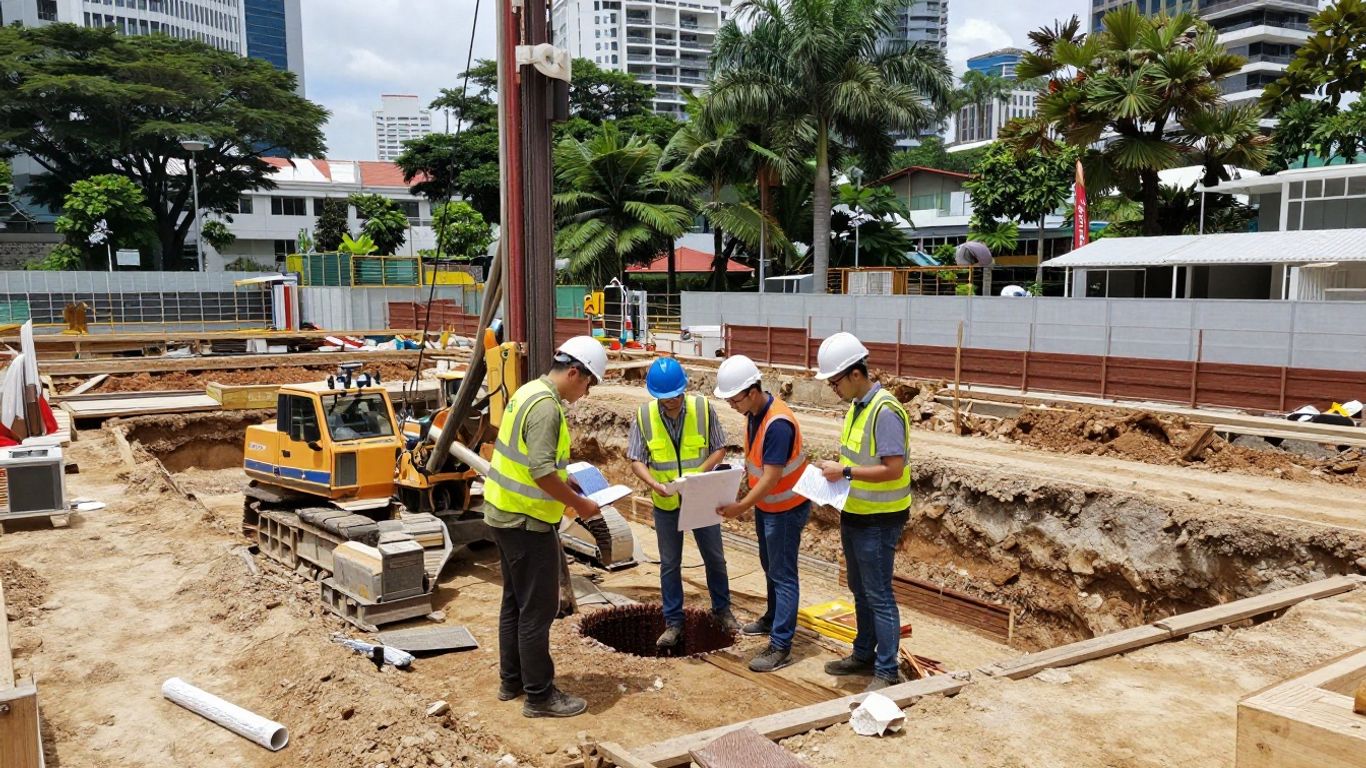
Parameter selection should follow the intended analysis and the stress paths expected during excavation. The geotechnical engineering reference illustrates why soil and rock mechanics, foundation conditions, and subsurface interpretation belong together rather than being treated as separate data exercises. In the report, include test provenance, representative values, exclusions, and the rationale for adopting lower-bound, best-estimate, or upper-bound parameters.
Groundwater observations deserve the same discipline as soil data. Record monitoring dates, seasonal context, perched water or confined layers, and any evidence that construction activities may alter the regime. If investigation coverage is sparse, use sensitivity cases to test the consequences of plausible layer elevations and strength or stiffness ranges instead of presenting a single, overly precise geological picture.
3. Select PLAXIS 2D or 3D based on project complexity
The choice between PLAXIS 2D and PLAXIS 3D should follow the mechanics of the problem, not the preference of the analyst. A two-dimensional section can be appropriate where the excavation and loading are sufficiently uniform along its length, while a three-dimensional model becomes more defensible when corners, irregular geometry, localized loads, or non-uniform support conditions govern the response. Explain the selection in terms of expected behavior and decision risk.
PLAXIS 2D includes staged construction, consolidation, safety analysis, and flow analysis for groundwater and dewatering effects. PLAXIS 3D provides true three-dimensional modeling for excavation corners, irregular shapes, non-uniform loading, inclined layers, and geological features. Those documented capabilities should be matched to the project geometry without implying that dimensional refinement alone guarantees greater accuracy.
A practical workflow may use a representative two-dimensional model for broad screening and a three-dimensional model for localized effects, provided the relationship between the models is explained. Compare compatible sections, boundary assumptions, material parameters, and construction stages. The report should make clear whether a 3D analysis is the primary design model, a sensitivity study, or a focused investigation of a particular interaction.
4. Choose and justify soil constitutive models and parameters
Constitutive modeling is where the ground investigation becomes a mechanical prediction. The selected model should reflect the soil behavior that matters for the ERSS question: initial stiffness, stress dependency, yielding, creep, small-strain response, or strength mobilization. A simple model can be suitable for preliminary work, but a more advanced model is justified only when its additional parameters are supported and its effect is understood.
The following comparison provides a concise way to connect model choice with the behavior being represented:
| Constitutive model | Useful representation | Typical justification |
|---|---|---|
| Mohr-Coulomb | Basic elastoplastic response | Preliminary analysis or limited parameter data |
| Hardening Soil | Stress-dependent stiffness | Improved deformation prediction under changing stress |
| Soft Soil Creep | Time-dependent behavior | Marine clay and consolidation-related settlement |
| HSsmall | Small-strain stiffness | Sensitive structures where modest movements matter |
The table is a starting point, not a license to select a model by name alone. Calibrate parameters against laboratory results where possible, document drained or undrained assumptions, and distinguish measured values from correlations. The report should also state which parameters control the predicted wall movement and whether the model captures the construction timescale relevant to the project.
5. Represent existing structures, utilities, and boundary conditions accurately
An ERSS model can be numerically polished and still be misleading if the neighboring environment is simplified carelessly. Existing buildings should be represented through defensible foundation levels, stiffness, geometry, and loading assumptions, with particular attention to basements, piles, retaining walls, and structural discontinuities. Where drawings are incomplete, identify the uncertainty and explain how it is addressed.
Underground utilities require a separate coordination exercise because their consequences are often governed by serviceability and disruption, not only collapse. Use available detection, as-built information, agency confirmation, CCTV records, and selective exposure where appropriate to establish alignment, depth, condition, and criticality. The boundary conditions should then reflect realistic restraint, drainage, and load-transfer behavior rather than treating every utility as an invisible line.
Set model boundaries far enough from the excavation to avoid artificial confinement, and define the base and lateral restraints consistently with the intended physical problem. Check ground surface geometry, surcharge extents, structural interfaces, and contact assumptions together. A forensic geotechnical evaluation can be a useful related reference when existing distress or uncertain structural condition requires evidence-based interpretation beyond the numerical model itself.
6. Simulate excavation sequences and temporary works installation
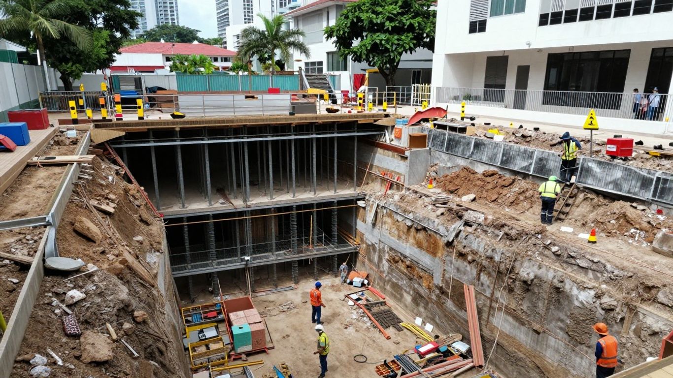
Construction staging is the central narrative of an ERSS analysis. The model should follow the actual sequence: establish the initial stress state, activate existing structures and loads, excavate by lifts, install each support level, apply dewatering measures where relevant, and continue until the intended formation or permanent condition is reached. The timing and order of these events can materially change the predicted response.
A compact staging register helps prevent omissions in a long analysis. It should identify the physical action, its model operation, and the result that must be checked:
- Initial conditions and in-situ stresses, including groundwater equilibrium.
- Excavation lifts and removal of soil in the modeled geometry.
- Installation and activation of walers, struts, anchors, slabs, or diaphragm-wall elements.
- Dewatering, drainage, consolidation, or recovery stages where they affect behavior.
After each stage, interpret the model rather than relying only on the final contour. Unexpected jumps may indicate an activation error, an incompatible interface, excessive unloading, or a boundary problem. A construction sequence animation can help communicate the order, but the report still needs tabulated stage results and engineering commentary.
7. Model groundwater, dewatering, and drainage effects
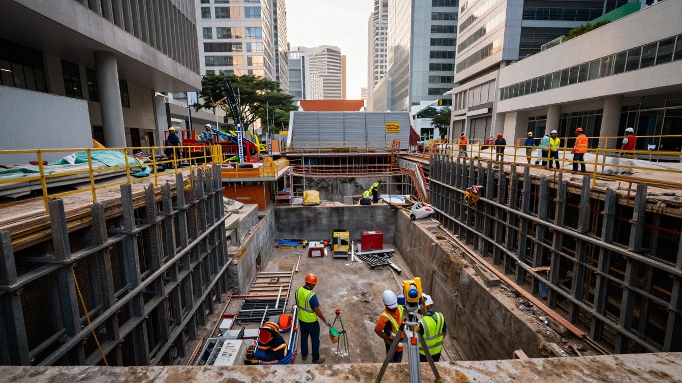
Groundwater is both a load and a contributor to soil behavior. Define phreatic levels, permeability contrasts, drainage paths, cutoff assumptions, and any confined pressure conditions before deciding whether a steady-state flow, transient flow, consolidation, or coupled approach is appropriate. The chosen hydraulic representation should correspond to the actual dewatering and drainage plan.
Dewatering may reduce hydraulic pressure while increasing effective stress and settlement outside the excavation. That interaction is particularly important near shallow foundations, compressible deposits, utilities, and structures with limited tolerance for differential movement. Model pumping or drainage changes in the same construction stages as the works, and compare them with a no-dewatering or alternative-control case where uncertainty is material.
Monitoring is the practical companion to groundwater analysis. Define observation points, trigger levels, response actions, and the relationship between field readings and model predictions. If field data show that the assumed water regime is wrong, the design team should treat that as a model update signal rather than forcing the measurements to fit the original report.
8. Verify mesh quality, convergence, and model sensitivity
Mesh generation should support the questions being asked. Refine around excavation corners, wall interfaces, strut connections, pile groups, abrupt layer changes, and areas where high gradients are expected, while avoiding an unnecessarily dense mesh in remote, low-interest regions. Mesh quality is not demonstrated by element count alone; it is demonstrated by stable engineering outputs under reasonable refinement.
Run at least one refinement comparison for critical sections and inspect whether wall displacement, settlement, structural force, and groundwater response are converging. Review calculation warnings, plastic points, load advancement, and time-step behavior. If a run completes but produces physically implausible mechanisms, convergence by itself should not be treated as validation.
Sensitivity analysis should focus on uncertain inputs that can change the decision. Vary stiffness, strength, permeability, groundwater levels, interface behavior, surcharge, wall stiffness, and construction timing as appropriate. Present the selected base case alongside the adverse cases and explain whether the design is controlled by movement, stability, structural demand, or an authority criterion.
9. Interpret ground movements and structural impact for ERSS checks
Finite element output becomes useful only after it is translated into engineering effects. Review lateral wall movement, ground settlement, heave, basal stability, strut or anchor forces, pore-pressure changes, and the timing of peak responses. Use deformation contours, stress paths, time curves, and stage-by-stage plots to identify the mechanism behind each governing value rather than reporting isolated maxima.
For nearby buildings, compare both absolute settlement and differential movement. Angular distortion, cracking risk, serviceability, foundation type, structural form, and existing condition may all influence the assessment. Predicted ground movements can be passed into a separate structural model as support settlements and lateral displacements when a detailed evaluation of member stresses, moments, deformations, or crack widths is required.
The interpretation should distinguish predicted values from acceptance criteria and monitoring actions. Avoid presenting a contour color as a pass or fail decision without stating the point location, stage, direction, sign convention, and applicable limit. Where results are close to a criterion, explain the uncertainty and identify practical mitigation such as sequencing changes, additional stiffness, reduced excavation exposure, improved drainage control, or enhanced monitoring.
10. Present transparent, review-ready results for BCA ERSS design reports
A review-ready report lets another engineer reconstruct the analysis without guessing. Include the geometry, soil profile, material parameters, interfaces, structural properties, groundwater conditions, mesh, boundaries, stages, loads, calculation settings, and output locations. Screenshots are useful, but they should support tables and narrative rather than replace them.
The results section should connect every headline value to a defined check. Show representative sections, critical stages, deformed meshes, movement profiles, structural force envelopes, pore-pressure changes, and sensitivity comparisons. State the limitations plainly, including missing investigation data, uncertain foundation information, idealized utilities, and the assumptions used to approximate three-dimensional behavior in a two-dimensional model.
Finally, align the numerical record with drawings, monitoring plans, temporary works details, and the professional engineer’s endorsement process. FEA consulting engineers commonly frame simulation findings through assumptions, methods, conclusions, and technical reports; that same discipline is valuable for geotechnical submissions. A clear audit trail gives BCA reviewers and project teams confidence that the ERSS design reflects the proposed works and can be checked against site observations.
Conclusion
A strong PLAXIS-based BCA ERSS report is less about producing attractive contours and more about building a defensible chain from investigation data to construction stages, groundwater behavior, movement predictions, structural impact, and submission decisions. When assumptions are explicit, model complexity is proportionate, and results are tied to monitoring and acceptance criteria, the analysis becomes a practical engineering record rather than a black box.
Frequently Asked Questions
What does ERSS mean in a construction project?
ERSS means Earth Retaining or Stabilizing System. It refers to the temporary works and associated design measures used to retain ground and control stability and movement during excavation and construction.
When is a two-dimensional model suitable for ERSS analysis?
A two-dimensional model is generally suitable when the excavation, soil conditions, support arrangement, and loading are reasonably uniform along the modeled direction. The report should explain why end effects and localized three-dimensional behavior are not governing.
When should a three-dimensional model be considered?
Three-dimensional analysis should be considered for irregular excavation footprints, corners, non-uniform loading, inclined strata, localized foundation interaction, pile groups, tunnels, or other conditions where a plane-strain idealization may miss the controlling behavior.
Which soil parameters most influence predicted wall movement?
Stiffness, strength, stress history, interface behavior, groundwater conditions, permeability, and construction timing can all be influential. Their relative importance depends on the soil profile, support system, excavation depth, and analysis stages.
How should groundwater be included in an ERSS model?
Define initial water levels, permeability, drainage paths, cutoff conditions, and the planned dewatering sequence. Assess how pressure changes alter effective stress and settlement, particularly outside the excavation and near sensitive structures.
What should a sensitivity analysis cover?
Sensitivity cases should address credible uncertainty in soil stiffness and strength, groundwater level, permeability, surcharge, wall or support stiffness, interface properties, and construction sequence. The cases should be linked to a design decision or acceptance criterion.
What makes an ERSS design report easy to review?
A reviewable report clearly documents the design basis, model geometry, parameters, stages, mesh, boundaries, groundwater assumptions, critical outputs, sensitivities, limitations, and checks. It also connects the numerical predictions with drawings, monitoring arrangements, and site controls.