
Introduction
Structural redundancy and progressive collapse checks in permanent ERSS design confirm that a permanent Earth Retaining and Stabilising Structure has multiple interconnected load paths, so if a single strut or anchor is lost, forces can redistribute without causing disproportionate collapse. In practice, progressive collapse checks test those single-member loss scenarios and verify that the remaining ERSS elements and permanent floor diaphragms can carry the redistributed loads in line with Singapore BCA requirements.
This article focuses on permanent basement and underground construction in Singapore: structural redundancy concepts in permanent ERSS, accidental load case evaluation, single strut and anchor failure analysis, load transfer into permanent floor diaphragms, progressive collapse mechanisms, design check procedures using 2D and 3D analysis, and the BCA submission documentation needed to demonstrate compliance. It does not cover purely temporary works analysis or shoring systems unrelated to permanent basement construction. The material is written for structural engineers, geotechnical consultants, and project managers who need to deliver safe, approvable permanent ERSS designs for basement and underground facility projects.
After reading this article, you will understand:
-
How alternate load paths function in permanent ERSS and why they prevent disproportionate collapse
-
What accidental load cases BCA Advisory Note 1/09 requires and how to model them
-
How single strut/anchor failure analysis works step by step
-
The difference between 2D, 3D, and experimental analysis methods for progressive collapse checks
-
What BCA submission documentation must include for redundancy verification
Understanding Structural Redundancy in Permanent ERSS
Structural redundancy in permanent earth retention systems refers to the degree of static indeterminacy; systems with more supports, connections, and continuous elements than the minimum needed for equilibrium contain backup load paths whose purposes are to redistribute forces and maintain stability after a local member fails. In Singapore’s geological context, where marine clay overlying sandy layers creates variable lateral pressures at different depths, redundancy directly determines whether a retaining wall system survives unexpected changes in soil loading or support loss.
Redundancy provides alternate load paths for structural safety. Permanent Earth Retaining Structures must accommodate unforeseen events and deterioration over their service life, which makes redundancy a design requirement rather than an optional enhancement. BCA Advisory Note 1/09 explicitly requires that ERSS designs address redundancy, including one-strut failure scenarios and accidental loads. For engineers preparing BCA structural submissions, demonstrating redundancy is a mandatory compliance item.
Load Path Mechanisms in ERSS
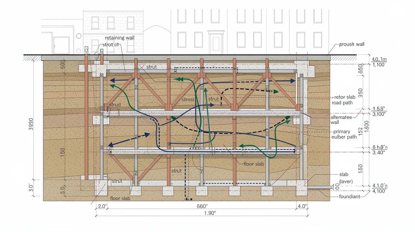
Primary load paths in permanent ERSS carry soil and water pressures from the retaining wall through struts, walers, or anchors to reaction points such as opposing walls or rock anchors. In a typical multi-level basement excavation, lateral earth pressure acts on the diaphragm wall, which transfers force through horizontal struts or ground anchors at each excavation level, and finally into the permanent floor slabs once construction is complete.
Alternate load paths activate when a primary element is removed or fails. For example, if a strut at one level is lost, the diaphragm wall must span a greater unsupported height, redistributing bending moments to adjacent strut levels. Permanent floor slabs can act as diaphragms to transfer lateral loads horizontally when temporary supports are removed, spanning across the missing support zone like a bridge during load redistribution. Redundant structures contain multiple interconnected paths for force travel; the design must verify that these alternate paths have sufficient capacity under the redistributed forces.
Redundancy provides structural forgiveness against material variability. A wall panel with connections to multiple strut levels and continuous reinforcement into permanent slabs has several independent mechanisms to carry load. A wall supported by a single row of anchors with no alternative support is a non redundant structure where loss of that row leads directly to failure.
Static Determinacy vs Indeterminacy in ERSS
Redundancy is defined by static indeterminacy in structural mechanics. A statically determinate propped cantilever wall with a single strut has zero redundancy: remove the strut, and the wall cannot maintain equilibrium. A wall propped at four levels with continuous walers and tied into permanent basement slabs is indeterminate to a high degree, meaning several elements can be lost before the system reaches a critical state.
Research on horizontal struts in deep excavations quantifies this using a redundancy index that measures how far the system is from becoming statically determinate. As struts are removed, the index drops toward a threshold below which the system behavior transitions from stable redistribution to progressive failure. Systems with higher indeterminacy provide more capacity for redistribution after component failure.
Designing for redundancy eliminates fracture-critical members. When every element in the system has at least one alternate path available, no single element’s failure can trigger disproportionate collapse. This principle shapes how engineers select the number of strut levels, waler configurations, and connections between temporary and permanent works.
The relationship between indeterminacy and collapse resistance leads directly to the question: what specific failure mechanisms must permanent ERSS design guard against?
Progressive Collapse Mechanisms and Structural Integrity in Permanent ERSS
Progressive collapse occurs from local damage triggering global failure. Collapse propagates through load-carrying elements when the system lacks sufficient redundancy or ductility to absorb and redistribute the forces released by a failed member. Earth Retaining Structures must consider structural robustness and localized damage as part of the design basis. The following sections address three categories of progressive collapse triggers in permanent ERSS.
Accidental Load Case Scenarios
Accidental loads represent unexpected external events that impose forces beyond the standard design loading. Singapore’s BCA Advisory Note 1/09 requires ERSS designs to include a minimum surcharge of 10 kPa to account for incidental loading from construction equipment, material storage, or adjacent structure loads. This 10 kPa value applies across all stages of construction for both temporary and permanent ERSS configurations.
In Singapore’s dense urban environment, accidental load cases extend beyond simple surcharge. MRT vibrations from adjacent tunnels impose dynamic loads on retaining walls. Piling operations on neighboring sites can generate impact loads that temporarily increase lateral earth pressure. Adjacent excavation works can undermine passive resistance at the toe of the retaining wall. Each of these scenarios must be evaluated as a separate load case in the design calculations.
Seismic loads, while less frequent in Singapore than in other regions, represent another accidental case. The design must verify that connections between wall elements and supports remain intact under combined axial, shear, and bending actions from any accidental load combination. Connection design should account for combined axial, shear, and bending actions to maintain robustness.
Single Strut and Anchor Failure Events
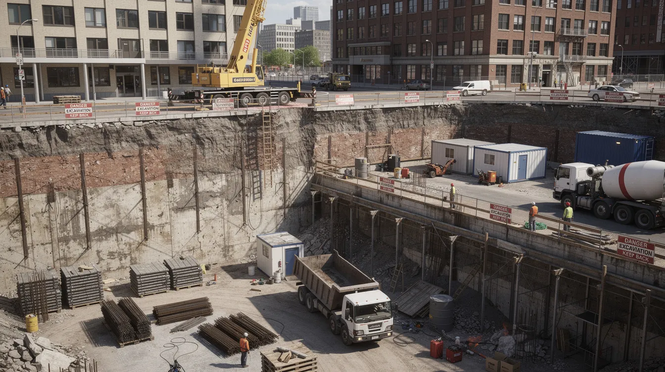
One-strut failure (OSF) analysis verifies that remaining supports can handle redistributed loads without failure. TR26:2010 clause 3.7.4 mandates that ERSS designs must remain safe under removal of a single strut, anchor, or tie-rod at each stage of construction. A redundancy assessment involves intentionally removing a critical structural element in analysis and checking whether the remaining system survives.
The consequences of strut or anchor failure vary by location. Research on deep excavations in loose to medium-dense sand found that failure of a strut at the middle elevation of the excavation produces the smallest strength redundancy; this central strut location represents the worst-case condition for OSF checks. In tied-back anchored systems, failure of lower-elevation anchors (which carry larger proportions of the total load due to greater depth) produces more severe effects than failure of upper anchors. Evaluation of stress redistribution analyzes if adjacent supports can bear the extra load from a failure.
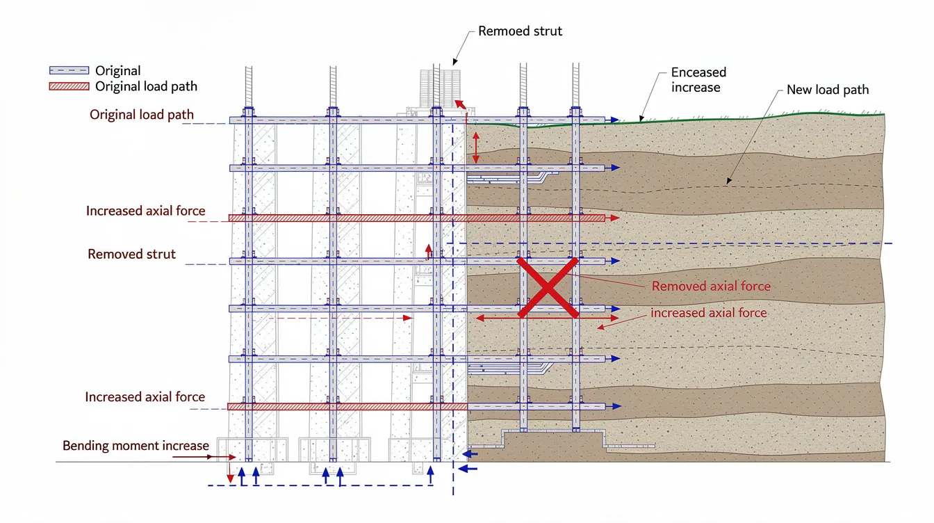
When a strut fails, adjacent struts experience increased axial forces. In multi-row anchor systems, failure of one row increases loads in the remaining rows, and capping beams experience increased bending moments. The load transfer coefficient depends on excavation depth and the elevation of the failed anchor. If the redistributed forces exceed the capacity of remaining elements, a chain reaction of failures follows.
For permanent ERSS where the temporary support system is integrated with the permanent structure (a “dependent” ERSS configuration), the permanent basement slabs must be designed to carry forces from temporary struts or rakers. This requirement applies during construction when temporary supports are being removed and permanent floor slabs take over as the primary lateral support system.
Zipper Failure Progression Patterns
Zipper failure describes the sequential loss of supports along a retaining wall, where one element’s failure overloads the next, which then fails, continuing until the entire wall system collapses. Structures lacking ductility are prone to progressive collapse because they cannot absorb energy through plastic deformation before fracturing.
The Nicoll Highway collapse in Singapore illustrates this mechanism. The retaining system used 800 mm thick reinforced concrete diaphragm walls with 10 layers of steel struts. Discrete element method modeling of this failure showed that the bottommost struts and wall panels became critical once excavation reached a depth that left the soil at the bottom without adequate support. Once these elements failed, the collapse propagated upward through adjacent strut levels. Studies based on this incident identified specific “dangerous time points” during excavation when the risk of cascading failure peaks.
Prevention of zipper failure requires designing ductile failure modes to allow warning before critical failures occur. Connections must allow rotation to maintain load transfer during distress, so that even as elements deform, they continue to carry some load rather than releasing all force instantaneously to adjacent members. Catenary action in floor slabs and membrane action in wall panels can provide secondary resistance after the primary load path yields, but only if connections are detailed to accommodate large deformations.
Understanding these failure mechanisms is necessary before selecting the appropriate analysis method for design checks.
Design Check Procedures and Analysis Methods
The choice of analysis method for progressive collapse checks depends on the excavation depth, number of support levels, proximity to adjacent structures, and whether the ERSS is independent or integrated with the permanent building. Finite element and numerical analysis tools allow engineers to model these scenarios with varying levels of detail and conservatism.
Single Element Removal Analysis
This procedure applies whenever a permanent ERSS design must demonstrate compliance with OSF requirements under BCA Advisory Note 1/09 and TR26. The analysis systematically removes one critical element at a time and evaluates the resulting load redistribution.
-
Identify critical members for removal: Focus on the lowest-level struts (highest soil pressure), central struts (least redundancy based on research findings), and anchors at the greatest depth. These locations consistently produce the worst-case redistribution scenarios.
-
Model load redistribution into permanent floor slabs and diaphragms: After removing the critical element, apply the redistributed soil pressure to the remaining supports. Where permanent floor slabs have been cast, model their role as horizontal diaphragms carrying the lateral load that the removed strut previously resisted.
-
Verify capacity of alternate load paths under redistributed forces: Check axial forces in remaining struts against buckling capacity. Check anchor pull-out resistance against increased demand. Check wall panel bending moments against section capacity over the increased unsupported span.
-
Check connection adequacy for increased demand: Connections between walers and struts, between wall panels and floor slabs, and between anchors and waler brackets must resist the redistributed forces. Robust connections ensure structural integrity by preventing premature failure under stress.
-
Document analysis with load path diagrams: BCA submissions require clear documentation showing the assumed failure location, the resulting force redistribution, and the capacity checks for all affected elements. Each construction stage needs a separate set of load path diagrams.
Sensitivity analyses help identify which assumptions most influence structural performance. Varying soil parameters, surcharge magnitudes, and stiffness values within credible ranges reveals which conditions control the design and where additional conservatism is warranted.
Load Redistribution Analysis Comparison
Selecting the right analysis method affects both accuracy and the time required for BCA submission preparation. The table below compares three approaches used in Singapore practice.
|
Criterion |
2D Plane-Strain OSF |
3D FE/DEM Numerical Modeling |
Experimental/Physical Modeling |
|---|---|---|---|
|
Accuracy |
Removes entire strut level; conservative by 20-40% in many cases |
Captures soil arching, panel interaction, lateral load sharing |
Reveals hidden failure modes not predicted by analysis |
|
Computational effort |
Low; standard software handles within hours |
High; requires detailed soil models and days of computation |
Very high; physical model construction and instrumentation |
|
BCA acceptance |
Well established; reviewers familiar with the approach |
Accepted with adequate documentation and peer review |
Supplementary evidence; not standalone for submissions |
|
Best application |
Standard excavations up to 15 m depth with regular geometry |
Complex geometry, deep excavations, adjacent sensitive structures |
Research validation or forensic investigation |
|
Limitations |
Neglects 3D soil arching; may force oversizing of members |
Requires more detailed soil data; less familiar to some reviewers |
Scaling issues with wall stiffness; high cost |
The conventional 2D approach models removal of an entire level of horizontal support, which is conservative because it ignores the ability of adjacent struts to share load laterally. Three-dimensional modeling reduces this conservatism by capturing how forces redistribute both vertically and horizontally. For projects where oversizing structural members has cost implications, the additional effort of 3D analysis is justified.
Redundant structures can survive unexpected local failures, but confirming this requires the analysis method to accurately represent system behavior under element removal. The transition from 2D to 3D methods represents a shift from assuming worst-case redistribution to modeling actual redistribution, with corresponding differences in member sizing and cost.
Common Challenges and Solutions
Engineers working on permanent ERSS in Singapore encounter several recurring issues when performing redundancy and progressive collapse checks. Robustness checks provide confidence that the structure can tolerate unforeseen events, but achieving that confidence requires addressing these practical obstacles.
Inadequate Floor Diaphragm Capacity for Redistributed Loads
Permanent basement slabs are often designed for gravity loads and standard lateral earth pressure, without accounting for the additional forces they must carry when temporary struts are removed and the slab becomes the primary lateral support. The solution requires the structural design team to include redistributed ERSS forces in the slab design from the outset. This means specifying additional reinforcement at slab-wall junctions, designing shear connections between the slab and diaphragm wall to transfer the full lateral load, and verifying that the slab has adequate in-plane stiffness to function as a diaphragm. Redundancy is critical for existing buildings and renovations where floor slabs were not originally designed for these forces.
Complex Load Path Definition in Multi-Level Basements
In basements with four or more levels, the number of possible load redistribution paths after element removal grows considerably. Tracing these paths manually is error-prone. Three-dimensional finite element models solve this by automatically computing force redistribution across all connected elements when one is removed. Engineers should build a single model that includes all excavation stages and temporary-to-permanent support transitions, then run systematic element removal at each stage. Structural modelling and analysis tools designed for progressive collapse assessment automate much of this process.
BCA Authority Submission Documentation Requirements
BCA requires that the Qualified Person (Design) submit forms from Advisory Note 1/09 listing all redundancy, OSF, and accidental load checks performed. The submission must include: calculations showing load redistribution for each construction stage, capacity verification of all alternate load path elements, connection design details with combined action checks, and monitoring plans for construction phases where temporary supports are removed. Engineers unfamiliar with BCA’s specific documentation format can reference the guide to BCA submission for temporary works or consult PE endorsement requirements for QP certification procedures.
Overconfidence in assumed redundancy without verifying connection capacities remains a persistent risk. Every alternate load path must be checked all the way through its connections, not just through the members themselves. Individual member strength alone does not guarantee system survival if the connections between members cannot transfer the redistributed forces.
Conclusion and Next Steps
Structural redundancy in permanent ERSS is what separates a system that survives a single element failure from one that experiences progressive collapse. The core design requirement is straightforward: verify that when any one critical member fails, the remaining structure has alternate load paths with sufficient capacity, ductility, and connection integrity to prevent a chain reaction leading to total collapse.
To implement these checks on your next project:
-
Map all primary and alternate load paths for each construction stage using 2D or 3D models appropriate to the project’s complexity
-
Perform single element removal analysis at each stage, focusing on lowest-level struts, central struts, and deepest anchors
-
Verify that permanent floor slabs are designed for redistributed ERSS forces, including in-plane diaphragm action
-
Document all redundancy and OSF checks in the format required by BCA Advisory Note 1/09
-
Engage an Accredited Checker for independent review of progressive collapse analysis on projects with high consequence of failure
Related topics worth investigating include temporary works design for ERSS during construction phases, geotechnical monitoring instrumentation for verifying design assumptions during excavation, and periodic structural inspection protocols for permanent retaining structures over their service life.
Additional Resources
-
BCA Advisory Note 1/09: Primary regulatory reference for ERSS design requirements in Singapore, including redundancy check forms and accidental load specifications
-
TR26:2010: Technical reference for deep excavation design, with clause 3.7.4 covering single element failure requirements
-
Analysis software: 3D finite element packages (Plaxis 3D, FLAC3D, Midas GTS NX) support element removal analysis and progressive collapse assessment for multi-propped excavations
-
BCA/ACES/IES circulars (2024): Recent clarifications on the distinction between independent and dependent ERSS configurations and their implications for QP appointment and design responsibility