
Introduction
Permanent ERSS walls in Singapore’s coastal zones face chloride concentrations that routinely exceed the 0.4% corrosion-initiation threshold within the outer 25 mm of concrete. Designing these earth retaining stabilising structure elements for durability requires specific provisions under SS 544: concrete grade C40/50 minimum, water-cement ratios at or below 0.45, nominal cover of 60–75 mm, and crack width limits of 0.2 mm under service loads. Without these measures, aggressive groundwater attacks structural elements through sulfate attack and corrosion, cutting decades off a wall’s intended service life.
This article covers concrete mix design specifications per SS 544, crack width control procedures, minimum cover requirements for different exposure classes, and sulfate/chloride resistance strategies for Singapore’s coastal soils. It is written for structural engineers, geotechnical consultants, and contractors involved in permanent retaining structures, basement construction, and deep excavation projects where groundwater conditions dictate material selection.
ERSS stands for Earth Retaining Stabilizing Structures. For permanent walls exposed to chloride-rich groundwater, SS 544 mandates a minimum concrete grade of C40/50, w/c ≤ 0.45, and w_max ≤ 0.2 mm crack limits to prevent ion migration to reinforcement within the design life.
After reading this article, you will be able to:
-
Select SS 544-compliant concrete mix parameters for XA, XD, and XS exposure classes
-
Implement crack width control using reinforcement detailing and direct calculation methods
-
Determine appropriate nominal cover depths based on site-specific groundwater chemistry
-
Specify sulfate-resistant binders and supplementary cementitious materials for coastal soil conditions
Understanding Aggressive Groundwater Environments in Singapore
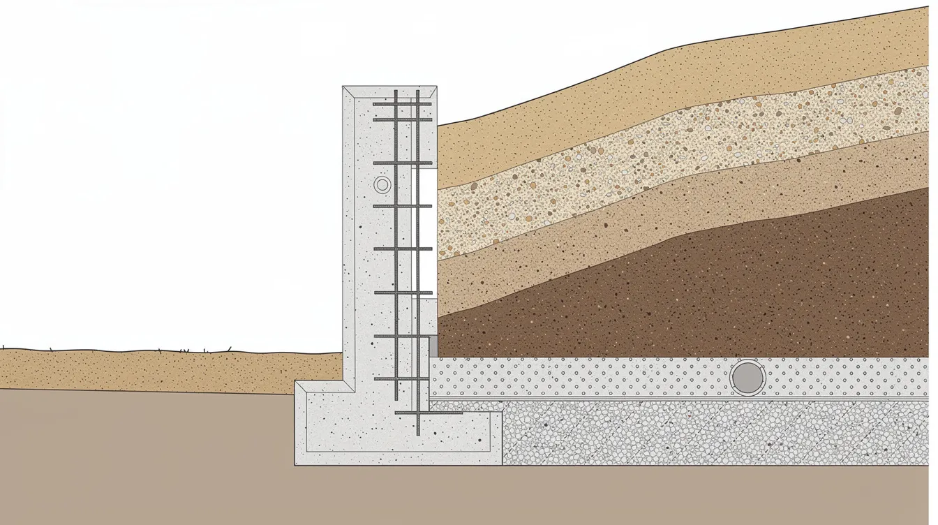
Aggressive groundwater conditions exist where dissolved chlorides, sulfates, or low pH levels in soil water chemically degrade concrete or initiate reinforcement corrosion. For permanent ERSS walls, these conditions determine exposure class selection under SS 544, which in turn controls every downstream specification: concrete grade, cover, and crack limits. Chemical testing of soil and groundwater is essential for assessing aggressiveness before the project’s design methodology is finalised.
Singapore’s coastal soil chemistry creates a particularly hostile environment for concrete structures. Seawater intrusion through porous coastal soils elevates chloride levels, while certain geological formations release sulfate ions into groundwater. The combination of high ambient temperature (averaging 27°C), near-constant humidity, and heavy rainfall accelerates the rate of ion ingress into concrete by comparison with temperate climates. SS 544 addresses this directly: for tropical climates including Singapore, elements should use at least one exposure class higher than what UK-based classifications would suggest.
Chloride and Sulfate Content in Singapore Coastal Soils
Groundwater beneath Marina Bay, Tanjong Pagar, and Jurong Island contains elevated chloride concentrations from tidal influence and seawater intrusion through porous coastal soils. Core samples taken from basement walls in one Singapore case study showed chloride content of approximately 1.5% by mass of cement at the 0–25 mm depth, dropping to about 0.5% at 50–75 mm. Both figures exceed the critical corrosion-initiation threshold of 0.4% by mass of cement.
Sulfate levels in groundwater vary across Singapore’s geological formations. Under SS 544 Part 1, water or soil extracts containing SO₄ below 400 mg/L fall into lower aggressiveness categories; concentrations above that threshold trigger stricter concrete specifications. In residual soils over Bukit Timah Granite and Old Alluvium, the groundwater table sits 1–3 m below surface. This shallow depth means retaining walls and deep foundation elements are immersed in chemically active water for most of their service life.
SS 544 Section 4.2.3 requires site-specific chemical analysis of both soil and groundwater before exposure class assignment. Soil characterization is crucial for predicting excavation stability and for determining the right concrete specification. Monitoring real site groundwater chemistry (chloride, sulfate, pH, temperature) is necessary because assumed values often underestimate aggressiveness; conditions vary across Singapore’s districts.
Groundwater Table Fluctuations and Exposure Classes in Deep Excavation
High groundwater levels create significant hydrostatic pressure on walls, and tidal cycles in coastal developments cause the water table to fluctuate by 0.5–1.5 m daily. This wet-dry cycling at the concrete surface accelerates chloride penetration compared to fully submerged conditions. Design for long-term hydrostatic pressure is vital for Earth Retaining Structures, and groundwater levels affect both excavation safety during excavation works and the design of the permanent structural system through changing wall loads.
Exposure class determination under SS 544 follows a site-specific assessment and should be aligned with the selection of support systems where excavation depth and groundwater pressure materially influence performance. XA2 applies to moderately aggressive chemical environments; XA3 covers severe conditions with high sulfate or chloride concentrations. For chloride-induced corrosion risk from seawater, XS classes apply; for chlorides from non-seawater sources (such as de-icing salts in industrial areas), XD classes govern. The distinction matters because each class sets different limits on w/c ratio, cementitious content, and cover.
Connecting the environmental assessment to concrete design: once the exposure class is established from groundwater chemistry data, SS 544 tables prescribe specific mix parameters. The following section details those specifications.
SS 544 Concrete Mix Design Specifications for Durability
With exposure classes assigned from site investigation data, SS 544 provides prescriptive comprehensive design requirements that control concrete permeability, chemical resistance, and service life. Lowering the water-cement ratio reduces permeability in concrete mixes, while the choice of binder type determines resistance to specific chemical attack mechanisms.
Minimum Concrete Grade and Water-Cement Ratio Requirements
For reinforced concrete under XS or XD exposure classes, SS 544 Table 4.1 specifies a minimum strength class of C40/50. For XA3 (severe chemical attack), C45/55 is the practical minimum because the lower w/c ratio needed to resist ion penetration produces strengths in that range regardless.
The maximum w/c ratio for XS and XD classes is 0.45, with many project specifications tightening this to 0.40 for XS exposure. For RC40/50 designated concrete with 20 mm maximum aggregate size, SS 544 sets the w/c limit at 0.45 with a minimum cementitious content of approximately 340 kg/m³. Portland-blastfurnace cement (CEM II/B-S) is preferred for these applications because the slag component binds chloride ions and reduces the C₃A-related vulnerability to sulfate attack. Use sulfate-resisting cement in concrete if high sulfate concentrations are present in the groundwater.
When selecting between C40/50 and C45/55 for a given project, the trade-off is straightforward: the higher grade delivers lower permeability and slower ion migration, but requires tighter quality control on placement, more careful aggregate selection, and increases material cost by 8–15% depending on local supply. For walls where two-sided chloride ingress occurs (tunnel walls, revetments), the higher grade is typically warranted because corrosion initiation accelerates when ions penetrate from both faces simultaneously.
Supplementary Cementitious Materials and Admixtures
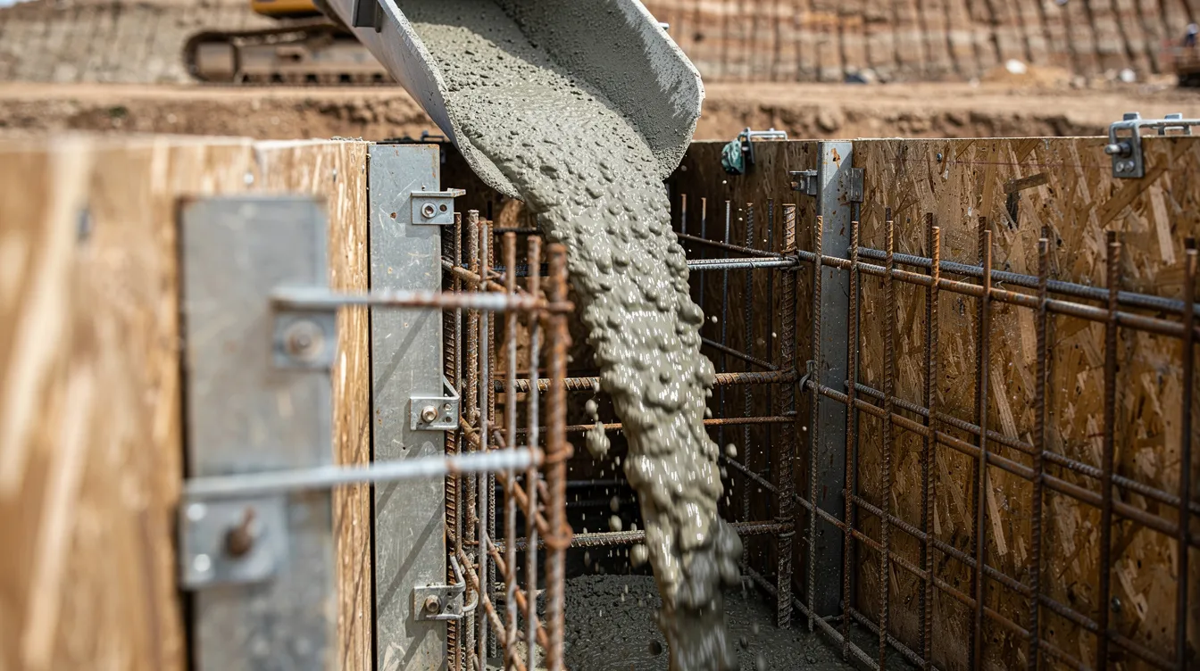
SS 544 Section 5.3 allows and encourages supplementary cementitious materials (SCMs) to reduce permeability. Fly ash replacement at 20–35% of total cementitious content lowers the diffusion coefficient for chloride ions. Studies on durability of concrete in Singapore confirmed that mixes with higher SCM content produced measurably slower chloride ingress compared to plain Portland cement mixes at the same w/c ratio.
Silica fume at 5–10% of cementitious content produces ultra-low permeability concrete suitable for the most aggressive XA3 and XS conditions. The pozzolanic reaction fills capillary pores in the cement paste matrix, reducing the rapid chloride permeability test (RCPT) values to below 1000 coulombs in well-cured specimens.
The trade-off with SCMs is early strength development. Fly ash and slag mixes gain strength more slowly than plain OPC, requiring extended moist curing periods of 14 days minimum to achieve full pozzolanic reaction. In Singapore’s construction sequence, where cycle times are tight, this needs to be coordinated with formwork scheduling.
Corrosion protection for steel components can include heavy-duty coatings or stainless steel. Corrosion-inhibiting admixtures (calcium nitrite-based, typically dosed at 10–30 L/m³) provide a secondary line of defense for rebar in marine environments. These are additive to, not substitutes for, the primary durability measures of low w/c, adequate cover, and crack control.
Aggregate Selection and Grading for Dense Matrix
Aggregates for ERSS wall concrete must meet SS 544-2 requirements for both physical grading and chemical composition. Granite aggregates are standard in Singapore. Maximum particle size is commonly 20 mm, with grading curves designed to produce a dense matrix with minimal void content.
For XS and XD exposure classes, aggregate chloride content is limited to ≤ 0.05% by mass of cementitious material. Aggregates must also meet limits on sulfate content and resistance to alkali-silica reaction. Low water absorption in aggregates (typically < 2%) reduces the total water demand of the mix, helping maintain the target w/c ratio during batching.
|
Parameter |
XA2 (Moderate) |
XA3 (Severe) |
XS/XD (Chloride) |
|---|---|---|---|
|
Minimum concrete grade |
C40/50 |
C45/55 |
C40/50 |
|
Maximum w/c ratio |
0.45 |
0.40 |
0.40–0.45 |
|
Min. cementitious content |
~340 kg/m³ |
~360 kg/m³ |
~340 kg/m³ |
|
Preferred binder type |
CEM II/B-S |
SRPC or CEM III |
CEM II/B-S + SCM |
|
Max aggregate chloride |
0.05% |
0.05% |
0.05% |
These mix parameters set the material baseline. The next section addresses how structural design and detailing work with the concrete specification to achieve the required durability.
Structural Design Requirements, Structural Adequacy, and Crack Width Control
Construction quality has a significant impact on the durability of retaining structures. A concrete mix meeting every SS 544 specification will still fail its durability objectives if cracks allow direct pathways for chloride and sulfate ions to reach the reinforcement. Structural design for permanent ERSS walls must therefore coordinate the shoring system and any temporary support used during excavation with crack width control, cover specification, and joint detailing as durability measures, not just strength provisions.
Crack Width Limitation Procedures (w_max ≤ 0.2 mm)
Cracks wider than 0.2 mm in chloride-exposure conditions allow ion migration to reinforcement at rates that can initiate corrosion within 5–10 years rather than the 50–100 year design life. Singapore’s infrastructure design standards (E/GD/09/106/A3) require crack width calculation at the serviceability limit state under quasi-permanent load combinations. The calculation checks crack width at the location of cover required for durability (c_min,dur) or at 40 mm from the outermost reinforcement, whichever produces the larger value.
To achieve w_max ≤ 0.2 mm in permanent earth retaining walls:
-
Calculate the minimum reinforcement ratio per SS EN 1992-1-1 Section 7.3.2, accounting for restraint from adjacent structures and the base slab
-
Limit maximum bar spacing to 150 mm centers for crack distribution; closer spacing (100–125 mm) is common in walls over 400 mm thick with high restraint
-
Verify crack width using the direct calculation method under service loads, including thermal and shrinkage effects from early-age concrete behavior
-
Add supplementary mesh reinforcement (T10 or T12 at 200 mm centers) at faces with high restraint ratios, particularly at wall-base connections
During staged excavation, strutting systems are checked against lateral soil and water pressures to ensure safety and allow works to proceed safely.
The 0.2 mm limit requires a higher reinforcement ratio than the 0.3 mm limit used for less aggressive exposures. For a typical 800 mm thick diaphragm wall in XS exposure, this translates to approximately 0.8–1.0% steel area per face compared to 0.5–0.6% for XC exposure. Limiting water ingress is critical for the durability of Earth Retaining Structures.
Minimum Cover Requirements for Different Exposure Classes
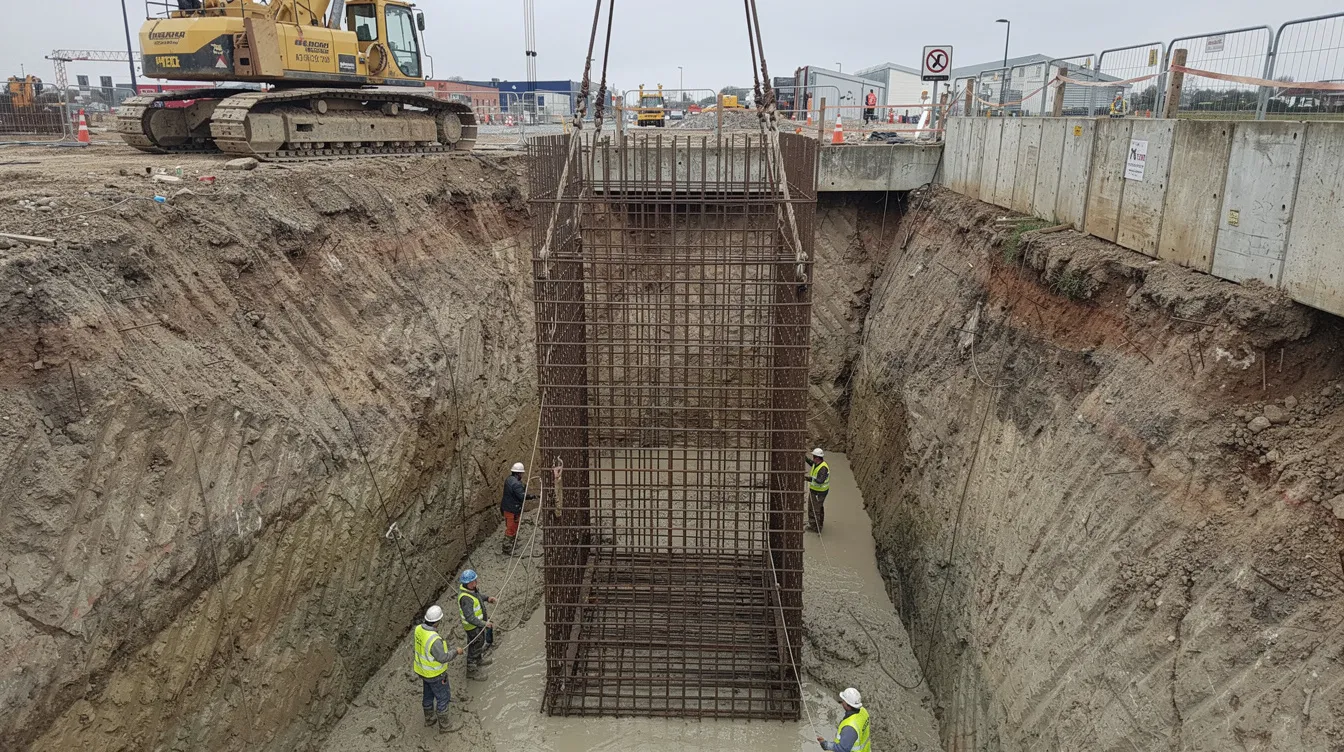
SS 544 specifies nominal cover as c_min,dur + Δc_dev, where Δc_dev accounts for construction tolerance. The LTA’s E/GD/09/106/A2 standard prescribes that for elements cast directly against soil (diaphragm walls, secant pile walls, reinforced concrete piles), c_min,dur applies with a deviation tolerance Δc_dev of ±10 mm, and diaphragm walls remain the industry standard for deep urban basement construction.
|
Exposure Class |
c_min,dur (mm) |
Δc_dev (mm) |
Nominal Cover (mm) |
Application |
|---|---|---|---|---|
|
XA1 |
40 |
+10 |
50 |
Mild chemical attack |
|
XA2 |
55 |
+10 |
65 |
Moderate sulfate/acid |
|
XA3 |
65 |
+10 |
75 |
Severe chemical attack |
|
XS2/XS3 |
60–65 |
+10 |
70–75 |
Submerged/tidal seawater |
|
XD2 |
55 |
+10 |
65 |
Chlorides, non-seawater |
Secant bored pile walls are also often selected in confined spaces because they minimize water infiltration compared with more open pile arrangements.
For ground-bearing slabs in contact with aggressive soils, a 75 mm minimum cover applies. Engineers should verify cover against structural requirements for chemical-resistant walls when the wall also serves containment functions.
Quality control of cover during construction uses electromagnetic cover meters calibrated to the actual bar size. Concrete spacers (not plastic chairs, which can crack under lateral loads) maintain cover during concreting. Designing permanent Earth Retaining Structures requires focus on geotechnical stability, but achieving that stability with adequate cover is what ensures the structure lasts.
Reinforcement Detailing and Joint Design
Stainless steel reinforcement (grade 1.4462 duplex) is specified for critical zones where cover alone cannot guarantee 100-year durability: wall-slab junctions, construction joints below the water table, and splash zones in partially submerged retaining walls. The cost premium of stainless steel over carbon steel is 4–6 times per tonne, so its use is typically limited to the outer 200 mm of cover concrete in specific locations. Where piling-induced vibration is a concern, joint and reinforcement detailing should also account for the risk to nearby structures’ integrity during construction.
Construction joints are sealed with hydrophilic waterstops that expand on contact with water, creating a compression seal within the joint. Sealing compounds rated for negative hydrostatic pressure per SS 637:2018 are applied at wall-slab intersections. Use waterproof membranes and drainage systems to enhance durability against groundwater, particularly on the positive (soil-contact) side of walls where accessible during construction. Robust drainage systems prevent water accumulation behind retaining walls and reduce the long-term hydrostatic load on joint sealants.
For projects requiring PE endorsement for civil and structural works, the Qualified Person certifying the ERSS design must verify that joint details comply with both structural adequacy and waterproofing requirements. A Qualified Person must certify excavation designs in Singapore, and the Building and Construction Authority and LTA, as the relevant construction authority, mandate strict safety protocols for excavation.
Common Durability Challenges and Solutions
Even with specification-compliant concrete and detailing, permanent ERSS walls in Singapore encounter recurring durability issues. The following covers the four most common failure modes and their mitigation.
Chloride-Induced Corrosion in Basement Walls
Core samples from one Singapore basement project revealed chloride content exceeding the 0.4% corrosion threshold at all measured depths up to 75 mm from the exposed face. Concrete cover of 50–70 mm, which met the original specification, proved insufficient because the actual chloride diffusion coefficient exceeded the design assumption.
For walls where post-construction testing reveals higher-than-expected chloride ingress, cathodic protection systems (impressed current or sacrificial anode) can extend service life by maintaining the reinforcement potential below the corrosion threshold. Penetrating lithium-silicate corrosion inhibitors applied during construction reduce the chloride diffusion rate by filling surface pores, but they are not substitutes for adequate mix design and cover. Permanent monitoring equipment aids in assessing structural health over time through embedded reference electrodes and corrosion rate sensors.
Sulfate Attack in Deep Foundation Elements
Sulfate attack causes expansion cracking in concrete containing ordinary Portland cement with C₃A content above 8%. SS 544 specifies sulfate-resistant Portland cement with C₃A ≤ 5% for XA3 conditions. For bored pile walls, secant pile walls, and diaphragm walls cast in sulfate-bearing Old Alluvium, CEM III/A with 50–65% ground granulated blast-furnace slag provides both sulfate resistance and reduced heat of hydration. By comparison, sheet pile walls are generally used for shallow to medium excavations and are often cost-effective for shallow excavations, unlike the deeper systems discussed in this subsection. In retaining applications, soldier piles are typically installed at about 1.5 m intervals, but the durability focus here remains on bored pile, secant pile, and diaphragm wall systems in aggressive groundwater.
In extreme exposure (SO₄ > 3000 mg/L in groundwater), sacrificial concrete layers of 50–75 mm beyond the structural section are sometimes specified. Protective coatings (coal-tar epoxy or polyurethane) on the soil-contact face provide additional barriers where site constraints allow application.
Construction Quality Control in Aggressive Environments
The gap between specified and achieved durability often traces to construction practice. SS 544-2 limits fresh concrete temperature to 38°C maximum, and strength development curing is based on 27 ± 2°C. In Singapore’s climate, concrete placed in the afternoon can exceed 38°C without ice or chilled water batching. The construction methodology for permanent ERSS walls should also include site safety controls for curing, cover verification, and groundwater exposure during placement.
Mandatory testing for permanent ERSS walls in aggressive groundwater conditions includes:
-
Rapid chloride permeability testing (RCPT) per ASTM C1202 on 28-day specimens
-
Chloride diffusion coefficient measurement on 90-day specimens
-
Sulfate resistance tests on mortar bars
-
Cover verification using calibrated electromagnetic scanners at pour completion
Enhanced curing with membrane-forming curing compounds, applied immediately after formwork removal, must continue for 14 days minimum. Moist curing (ponding, wet hessian) is preferred over spray-applied membranes for walls where SCM replacement exceeds 25%, because the pozzolanic reaction requires sustained moisture availability. ERSS works and stabilising systems require Licensed Specialist Builders as per Building and Construction Authority regulations, and contractors must demonstrate compliance with these curing requirements.
Groundwater Management During Construction
Improper sequencing of excavation phases during excavation works can reduce wall performance, and dewatering for deep excavations in Bukit Timah granitic residual soils can draw the water table down by several meters, increasing permeation through partially cured concrete. Excavation in dense areas risks damaging buried utilities if dewatering is not controlled.
Dewatering system design must prevent concrete washout during tremie placement of diaphragm wall panels. In some stages, earth filling may be needed to maintain excavation shape and stability as site conditions change. For very deep excavations, recharge wells on the far side of the excavation maintain groundwater levels beneath adjacent structures to prevent settlement. Trigger levels are set to ensure immediate action during excavation if ground movement monitoring detects displacement beyond specified limits. Settlement markers installed on nearby structures provide early warning of differential movement.
Periodic access for maintenance should be designed into drainage systems for longevity. This means manholes at maximum 30 m spacing along permanent subsoil drains and accessible sumps for pump maintenance.
Selected support systems for shallower zones may include sheet pile or soil nails, depending on excavation depth and soil conditions. Addressing these construction-phase challenges before they become durability problems requires integrated planning between temporary works design and permanent works specification.
Conclusion and Next Steps
Durability of permanent ERSS walls in Singapore’s aggressive groundwater depends on three linked systems: SS 544-compliant concrete mix design (C40/50 minimum, w/c ≤ 0.45, SCM incorporation), structural detailing for crack control (w_max ≤ 0.2 mm with bar spacing at 150 mm or less), and adequate cover (65–75 mm nominal for XA2/XA3/XS classes). Each system compensates for the others’ limitations, but none alone is sufficient.
To implement these requirements on your next project:
-
Commission site-specific groundwater chemical analysis (chloride, sulfate, pH) at the project location before finalizing exposure class selection
-
Specify concrete grade and binder type based on the measured aggressiveness, not assumed default values
-
Detail reinforcement for 0.2 mm crack width under quasi-permanent loads, verifying with direct calculation rather than deemed-to-satisfy rules
-
Implement enhanced quality control: RCPT testing, cover verification at every pour, and 14-day minimum moist curing
For related design considerations, structural modelling and analysis of permanent ERSS walls should incorporate long-term creep and shrinkage effects. Waterproofing integration per SS 637:2018, long-term corrosion monitoring with embedded sensors, and maintenance access provisions for drainage systems are topics that extend from the durability design covered here. A structural inspection during the first five years of service can identify early distress signs before they progress to structural failure.