
Introduction
Alert thresholds for inclinometers, piezometers, and ground settlement markers determine whether an excavation proceeds safely or triggers a work suspension. In Singapore, the Building and Construction Authority (BCA) requires every Earth Retaining and Stabilising Structures (ERSS) plan to specify these thresholds before excavation begins. Getting them wrong costs time if set too tight (false alarms halt production) or risks structural failure if set too loose.
This guide covers threshold establishment for deep excavation monitoring, alignment with finite element analysis (FEA) predictions, and compliance with BCA Approved Document V7.08. It is written for structural engineers, geotechnical consultants, project managers, and regulatory compliance specialists working on excavation projects in Singapore.
The direct answer: set Alert level at 60–70% of the Work Suspension Level (WSL), Action level at 85–90% of WSL, and WSL itself at the BCA-prescribed maximum allowable deflection for the applicable zone and ground type. These percentages apply to inclinometer, piezometer, and settlement marker readings alike, scaled to the FEA-predicted maximum values for each instrument.
After reading this guide, you will be able to:
-
Calculate instrument-specific thresholds from FEA outputs and BCA zone classifications
-
Calibrate FEA models using site investigation data for credible deflection predictions
-
Configure alert settings for each instrument type with appropriate safety margins
-
Create alerts and response protocols tied to excavation stages
-
Navigate common problems such as false alarms, model uncertainty, and instrument drift
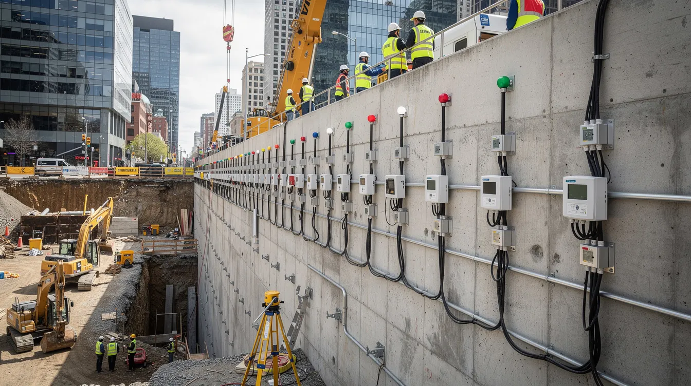
Understanding Instrumentation Alert Systems and Alert Notifications
Singapore’s BCA mandates an alert notification framework for all excavations exceeding 6 m in depth or located near adjacent structures. Under BCA Approved Document V7.08, the Qualified Person (QP) must determine allowable limits of ground deformation and changes in groundwater levels, then design instrumentation and monitoring programmes around those limits. Alerts are generated when specific conditions are met at each monitoring point. The system exists to create a window between “something is moving” and “something has failed.”
Alert Condition vs Alarm vs Action Levels
The BCA framework operates on a tiered system. The Alert Level is defined as 70% of the Work Suspension Level (WSL). When an instrument reading crosses this point, the response is to increase monitoring frequency and review the excavation sequence. No work stoppage is required, but the project team must act within the same working day.
The Action Level, typically set at 85–90% of WSL, is not explicitly codified in BCA documents but is standard industry practice in Singapore. At this level, contingency measures become active: additional struts, grouting, or partial suspension of certain works. The WSL itself equals 100% of the maximum allowable deflection. Crossing it triggers immediate work suspension and a full safety review before any resumption.
Alerts remain until dismissed manually or automatically, depending on the monitoring platform configuration. Some monitoring platforms also generate alerts when storage space runs low, so data continuity is not compromised. You can sort alerts by time or severity in the manager interface, and in some systems select recipient or visibility settings from a drop down menu, which helps site teams prioritize responses during the construction phase when multiple instruments may be triggered simultaneously.
Critical Monitoring Parameters
Three instrument categories form the core of any deep excavation monitoring programme. Inclinometers measure lateral wall deflection in diaphragm walls, secant pile walls, and sheet pile systems. Piezometers track pore water pressure and groundwater drawdown during dewatering. Settlement markers and robotic total stations measure vertical movement of adjacent structures and ground surface.
Each parameter connects to a different failure mode. Lateral wall deflection beyond design limits can lead to wall collapse or excessive ground loss. Piezometric head drops below safe levels risk basal heave. Settlement of adjacent buildings beyond tolerable limits damages structures and utilities. The relationship between ground settlement monitoring and adjacent building protection is direct: in soft clay conditions, ground settlements can reach 0.5% of excavation depth (H), translating to 100 mm for a 20 m excavation, enough to crack masonry walls.
Understanding how these parameters interact with FEA predictions is the foundation for setting thresholds that are neither recklessly loose nor operationally disruptive.
Finite Element Analysis Integration for Threshold Setting
FEA models generate the predicted deflection profiles that anchor every threshold value. Without a calibrated model, threshold setting becomes guesswork. The quality of the FEA output determines whether the alert condition for each instrument reflects actual site risk or an arbitrary number.
FEA Model Calibration Requirements
Soil parameter validation starts with site investigation data. CPT, SPT, and vane shear test results provide undrained shear strength and stiffness moduli. In Singapore’s Old Alluvium formation, sediment layers can extend to approximately 195 m depth with variable stiffness; the overconsolidation ratio and modulus reduction curves must be explicitly defined in the finite element model. A 2021 parametric sensitivity study of deep excavations in Singapore’s Old Alluvium found that allowable maximum wall deflection ranges from 0.5% to 1.0% of excavation depth depending on geotechnical conditions and nearby structure sensitivity.
Wall stiffness modeling requires accurate representation of the retaining system. Diaphragm walls typically range from 0.8 m to 1.5 m thick panels. When cross walls are included (0.8–1.0 m thick at approximately 6 m spacing), measured deflections drop to 0.07–0.12% of H, compared with 0.2–0.5% H in conventional braced systems. The FEA model must represent the actual support system installed, not a generic equivalent.
Construction sequence simulation is where many models fail. Staged strut installation, cross wall hacking, and dewatering produce different peak deflections at different excavation depths. Maximum wall deflections often appear during base slab installation, when the lowest strut level bears the full excavation load. The FEA model should simulate every excavation stage with props and supports in place at the correct elevations.
Threshold Calculation Methodology
Once the FEA model produces predicted deflection profiles, the threshold calculation follows BCA zone classifications. Under Approved Document V7.08:
-
Zone 1 (existing structures within distance < H from excavation face): maximum wall deflection ≤ 0.5% of H
-
Zone 2 (structures between H and 2H): ≤ 0.7% H
-
Zone 3 (structures more than 2H away): ≤ 0.7% H for Ground Type A (stiff clays, residual soils, medium to dense sands) or ≤ 1.0% H for Ground Type B (soft clays including Kallang Formation)
The QP must adopt the more stringent value between the BCA zone-based deflection limit and what is required to protect adjacent structures. This means that even if the zone classification permits 0.7% H, a sensitive heritage building nearby may require the WSL to be set at 0.3% H or lower.
Model uncertainty, soil parameter variability, and instrument accuracy all introduce error. To account for these, partial factors are applied. If the FEA predicts 120 mm maximum deflection but the BCA limit is 100 mm (Zone 1, 0.5% of a 20 m excavation), the WSL is set at 100 mm regardless of the prediction. The alert level becomes 70 mm (70% of WSL) and the action level approximately 90 mm.
Validation Against Historical Data
Comparing FEA predictions with measured data from completed projects is the most reliable calibration check. In the CTE Phase II excavation case, lateral wall deflections in soft soil overlying stiff soil were less than 0.5% of H. In composite soft layers less than 0.9H or 0.6H thickness, movements stayed below 0.35% H.
An Old Alluvium excavation study produced a direct comparison: FEA predicted 18 mm lateral deflection at a specific stage, while the inclinometer measured 14 mm at the same excavation level (1 m below strut S2, for H approximately 20–24 m). That 22% difference between predicted and measured values is typical. At the Marina South 26 m deep excavation in marine clay, deviation between predicted and measured deflection was generally within 20%.
For projects in Bukit Timah Granite residual soils, observed deflection profiles at Cashew station showed deflections lower than FEA predictions, with settlements becoming the controlling parameter rather than lateral wall movement. This highlights why both instruments must be monitored and why a single threshold approach across all soil types does not work.
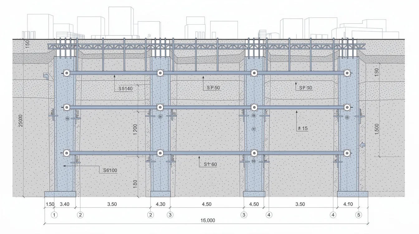
Instrument-Specific Alert Threshold and Alert Settings Configuration
Each instrument type requires different threshold values, measurement intervals, and response protocols. The following sections apply the FEA alignment principles to specific monitoring equipment commonly used in temporary works and ERSS projects.
Inclinometer Alert Thresholds
Inclinometer casings must be installed before excavation begins, grouted into the retaining wall or the ground behind it. Readings are taken at 0.5 m depth intervals to build a deflection profile that shows where the wall is moving and by how much.
For a 25 m deep diaphragm wall excavation in soft clay (Ground Type B) with adjacent buildings in Zone 1, the thresholds work out as follows. WSL = 0.5% × 25 m = 125 mm. Alert level = 70% × 125 mm = approximately 87 mm. Action level = 90% × 125 mm = approximately 112 mm. If the same excavation were in Zone 3 with no sensitive structures nearby, WSL = 1.0% × 25 m = 250 mm, giving an alert at 175 mm.
In high-stiffness systems with cross walls, where actual measured deflections fall to 0.07–0.12% H, the thresholds tighten. If FEA predicts 30 mm maximum deflection for a 25 m deep excavation with cross walls, setting the alert at 70% gives 21 mm and the action level at 27 mm. The difference between alert and action is only 6 mm, which demands precise instrumentation with resolution better than 1 mm.
You can configure alert settings to notify the project team via email notifications when readings approach these thresholds. Email notifications can be sent to specific users for alerts, ensuring the Qualified Person receives immediate notification at every level.
Piezometer Monitoring Thresholds
Piezometer threshold setting follows a different logic than inclinometers because the failure mode is hydraulic, not mechanical. During dewatering, the primary concern is basal heave: if the piezometric head in the aquifer below the excavation base drops too far, uplift pressure can exceed the weight of the soil plug and cause catastrophic failure.
Set the Alert level when the piezometric head drops to within 2 m above the excavation base. The Action level activates if the drop rate exceeds 1–2 m per hour, indicating potential hydraulic connection to the excavation. WSL is reached when head levels approach the point where uplift forces threaten wall base stability.
BCA’s Engineering Group Document for piezometer installation stipulates that the porous element must be at least 125 mm long, filters must be pre-soaked, and installation depth and stage must be recorded. Placement at the correct depth relative to permeable strata is essential; a piezometer installed 2 m above the target sand layer will miss pressure changes entirely.
In residual soils with fractured rock or high permeability, groundwater drawdown causes settlement that can exceed wall deflection. Research on braced excavation performance in residual soils at 20–24 m depth found ground settlements were larger than wall deflections when permeability was high. This means piezometer thresholds in such soils should be more conservative relative to water table lowering rate, and settlement markers become the primary control instrument rather than inclinometers.
Settlement Monitoring Configuration
Settlement marker thresholds depend on the sensitivity of the structure being protected, not just the excavation depth. For modern commercial buildings with reinforced concrete frames, total settlement alert thresholds of 15–20 mm are typical. Heritage buildings, unreinforced masonry, or structures with existing distress require much tighter limits of 10–15 mm or even lower.
Automated total stations (robotic total stations) with 1 mm precision are standard for adjacent building monitoring. Prisms are installed on the building facade, and readings are taken automatically at intervals ranging from 30 minutes to 2 hours. Differential settlement between adjacent prisms matters more than absolute settlement: 10 mm over 5 m horizontal distance (1:500 angular distortion) is a common trigger for masonry cracking.
Structural and facade inspections before excavation begins establish baseline conditions. A pre-construction condition survey documents existing cracks and distortions so that any new movement can be attributed to the excavation rather than pre-existing conditions.
Real-Time Data Integration and Email Notifications Systems
|
Instrument Type |
Alert Frequency |
Data Transmission |
Response Time |
|---|---|---|---|
|
Automated Inclinometers |
Every 2 hours |
Wireless/GSM |
15 minutes |
|
Vibrating Wire Piezometers |
Every 1 hour |
Datalogger/Cloud |
30 minutes |
|
Robotic Total Station |
Every 30 minutes |
WiFi/Ethernet |
5 minutes |
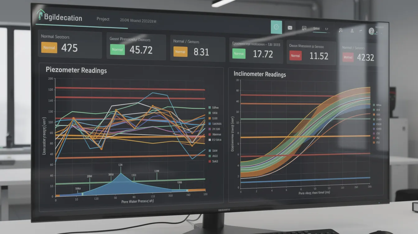
You can set alert frequency to daily or hourly checks depending on the excavation stage. During early excavation (first strut level), daily monitoring is sufficient. As excavation approaches full depth and base slab construction, increase to hourly or better. Alerts can be configured to trigger on specific conditions and sent to the project team’s email account or displayed on a mobile device dashboard. You can create alerts on user-defined dashboards that show real-time instrument readings against threshold values, giving the site team a live alerts page.
The choice of monitoring frequency should match the excavation risk profile. A 15 m excavation in stiff residual soil with no adjacent buildings within 2H does not need the same monitoring density as a 25 m excavation in marine clay next to an MRT tunnel.
Common Challenges and Solutions
Three recurring problems undermine threshold reliability on Singapore excavation projects.
FEA Model Uncertainty
Soil parameter variability is the primary source of FEA error. Undrained shear strength in Singapore marine clay can vary by 30–40% across a single site. A study on diaphragm walls with cross walls found that assuming “clean contact joints” between panels overestimates wall stiffness, producing unconservative deflection predictions. The practical response: apply a safety factor of 1.3–1.5 to FEA-predicted deflections when setting thresholds, and use the more stringent value between the factored prediction and the BCA zone limit.
Bayesian hierarchical models (HBM) represent a newer approach. These models combine deflection data from early excavation stages with a statistical database of prior projects to produce confidence intervals around predictions. Setting the alert threshold where the upper bound of the 95% confidence interval reaches WSL provides a probabilistic safety margin that tightens as more data becomes available during the project. This is an active area of research; a pre-defined set of alerts based on statistical thresholds can be enabled once the model accumulates sufficient site-specific data.
Instrument Installation Errors
Inclinometer casing misalignment, piezometer filter placement at the wrong depth, and settlement marker baseline readings taken after ground has already moved all produce systematically incorrect data. Implementation of installation QA/QC procedures is mandatory. For piezometers, this includes verifying filter element length (≥ 125 mm per LTA Engineering Group Document requirements), checking seal integrity, and recording installation depth against the borehole log.
For inclinometers, the casing must extend at least 3 m below the expected zone of influence to establish a stable reference point. If the tip moves, all readings are compromised. Redundant installations at critical wall sections (every 10–15 m of wall length) provide cross-checks. The Resident Engineer should verify instrument locations and orientations before excavation begins.
False Alarm Management
Temperature drift, barometric pressure changes, and electronic instrument drift can all trigger threshold exceedances that do not reflect actual ground movement. A single inclinometer reading that spikes 5 mm between two consecutive measurements, then returns to the previous trend, is more likely instrument noise than wall failure.
Establish graduated response protocols that distinguish genuine structural movements from artifacts. Trending analysis over multiple reading cycles is the primary tool: a genuine movement appears as a consistent trend across multiple instruments and multiple reading intervals. Cross-checking inclinometer data with survey markers and piezometer readings adds another layer. If the inclinometer shows 3 mm of movement but the adjacent settlement markers and piezometers show no change, the reading warrants investigation rather than alarm. Alerts can be marked as public or private in settings to manage information flow: confirmed alerts go to the full project team, while suspected instrument anomalies are reviewed internally first.
Conclusion and Next Steps
Alert thresholds for construction monitoring instruments are percentages of FEA-predicted maximum deflections, anchored to BCA zone classifications and ground type. Alert at 60–70% of WSL, Action at 85–90%, and Work Suspension at 100%. These values must be documented in the ERSS plan and referenced in monthly declarations per BCA Advisory Note 1/09, which requires the QP to declare whether alert or WSL levels have been exceeded.
To implement these thresholds on your next project:
-
Conduct site investigation with CPT, SPT, and vane shear tests sufficient to characterize all soil layers within the excavation zone of influence
-
Develop a calibrated FEA model that simulates the full construction sequence, including strut installation, dewatering stages, and base slab construction
-
Classify adjacent structures by BCA zone (1, 2, or 3) and ground type (A or B) to determine WSL percentages
-
Select instruments and configure alert notification protocols with graduated response procedures for Alert, Action, and WSL levels
-
Train site personnel on response procedures; the QP supervision framework should define who receives each alert level and their required response time
Related topics worth exploring include BIM integration for construction information management, which automates the link between monitoring data and design models, and Bayesian updating methods that refine thresholds as construction progresses.
Additional Resources
-
BCA Approved Document V7.08: wall deflection limits by zone and ground type, AAA system requirements
-
LTA Engineering Group Document EGD09104: piezometer installation specifications including filter element requirements and QA/QC procedures
-
Singapore case studies from the CTE Phase II depressed expressway and Marina South circular shaft excavations, which demonstrate measured deflections against FEA predictions in soft clay conditions