
Introduction
Permanent retention design for deep excavation shafts in the Jurong Formation demands an integrated approach to rock socketing, wedge stability analysis, and groundwater management across one of the most geologically variable sedimentary rock masses in Southeast Asia. Singapore’s sedimentary Jurong Formation – dating back to the Late Triassic period with LA ICP-MS U-Pb zircon ages of 240.6 ± 1.2 Ma – presents engineers with interbedded sandstone, siltstone, mudstone, and shale layers where rock quality can change significantly over short distances. Designing permanent shafts in this environment differs fundamentally from temporary shaft design due to the need for long-term stability under sustained groundwater pressures, weathering effects, and load transfer through highly variable rock mass properties.
This article covers the structural detailing and construction integration requirements for permanent retention systems in deep excavation shafts exceeding 30 metres in Jurong Formation bedrock. The scope encompasses rock socket capacity assessment, wedge failure prevention through discontinuity mapping, rock bolt anchor design and installation procedures, and water inflow management strategies – all within the regulatory framework of Singapore Standards CP4 and BCA guidelines. Topics outside this scope include soft-ground temporary excavation support and marine foundation design.
The target audience includes structural engineers, geotechnical consultants, and construction professionals working on deep basement projects, underground storage cavern excavation, and infrastructure shafts in Singapore’s sedimentary geology. Whether designing access shafts for rock cavern construction or deep sewerage tunnel shafts, the principles covered here apply directly to engineering rock mass classification challenges unique to the Jurong Formation.
Direct answer: Permanent retention design in the Jurong Formation requires integrated rock socketing analysis calibrated to lithology-specific UCS values (ranging from <30 MPa in weathered mudstone to >90 MPa in fresh sandstone), wedge stability assessment using stereographic projection of mapped discontinuities, and robust anchor systems with corrosion protection – all supported by probe-and-grout groundwater control where hydraulic conductivity of rock masses is around 1.73 × 10⁻⁶ m/s.
Key outcomes from this article:
-
Rock socket design optimization for interbedded sedimentary rock with variable strength profiles
-
Wedge failure prevention strategies using kinematic analysis and rock bolt reinforcement
-
Anchor load calculation methods accounting for weak mudstone interbeds and joint planes
-
Water inflow management techniques including pre-grouting and permanent drainage integration
-
Construction sequencing protocols for shafts exceeding 50 metres in fractured rock masses
Understanding the Jurong Formation for Deep Excavation Design
The Jurong Formation is a Late Triassic to Early Jurassic sedimentary rock mass underlying much of western and southwestern Singapore, including Jurong Island. It consists of interbedded sandstone, siltstone, mudstone, and shale – typical sedimentary rocks that have undergone low-grade metamorphism, folding, and faulting due to lateral basin compression. In certain zones, pyroclastic lava intruded into the sequence, introducing pyroclastic rocks and triggering subsequent thermal metamorphism that altered the engineering geological properties of adjacent beds. The formation also contains localized limestone beds where cavities can extend to depths of 60 metres, creating additional hazards for deep shaft construction.
For deep excavation design, the highly variable Jurong Formation presents a dual challenge: the rock mass strength and deformation modulus change rapidly between lithological units, while structural discontinuities (joints, bedding planes, faults) create potential failure surfaces that govern shaft wall stability. Understanding these characteristics is the foundation of any permanent retention design in this geological setting.
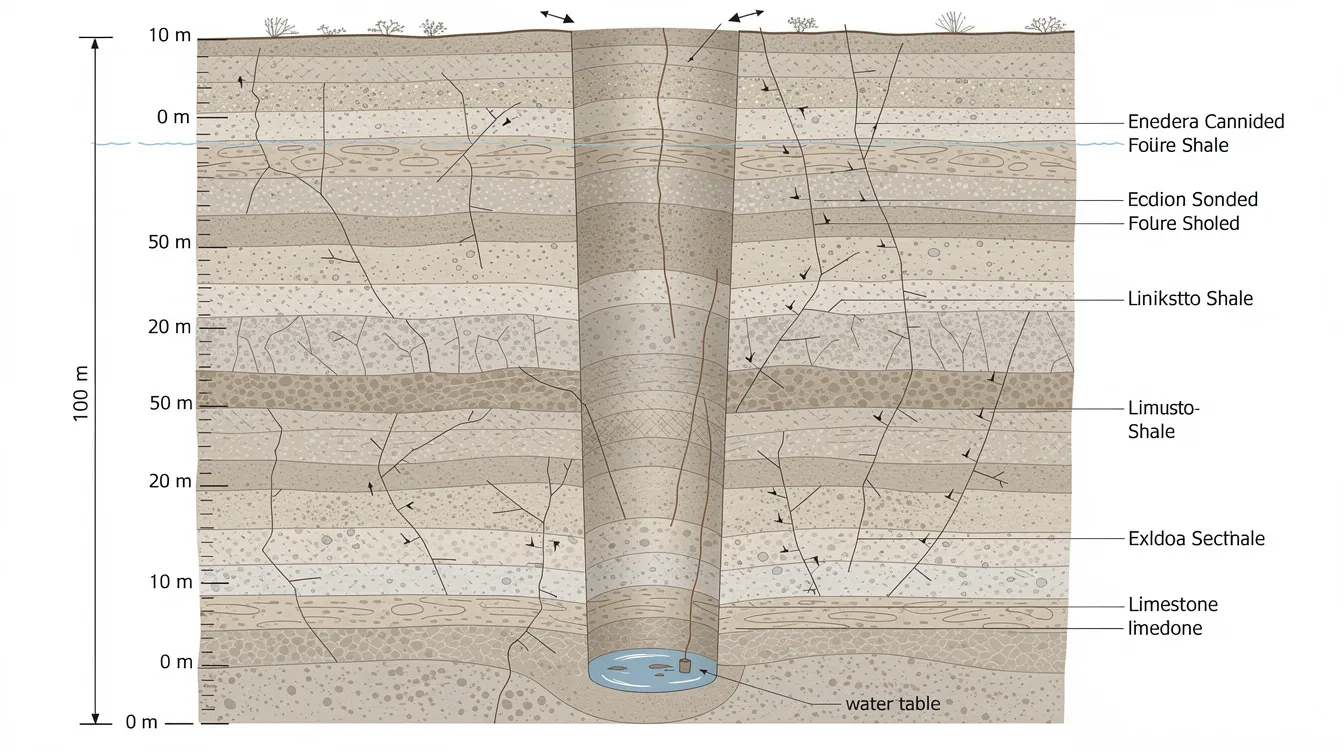
Geological Characteristics Affecting Retention Design
The engineering rock mass classification of the Jurong Formation reveals substantial variability in rock mass quality. Geological Strength Index (GSI) values in the formation typically range between 45 and 55 for moderately jointed rock masses, though values drop considerably in heavily weathered or faulted zones. Weathering grades per Singapore Standard CP4:2003 classify constituted rocks from Grade I (fresh intact rock) through Grade V (completely weathered to soil-like material), and engineers must apply the appropriate approach – Approach 2 for stronger beds like sandstone and conglomerate, Approach 4 for weaker mudstones and highly weathered zones.
The mechanical properties show wide banding tied to rock type. Compiled data from over 1,000 unconfined compressive strength tests across multiple projects reveals median UCS values for fresh sandstone (Grade II–III) of approximately 67–90 MPa, siltstone at ~35–45 MPa, limestone at ~65 MPa, and mudstone often below 30 MPa in weathered zones. Tangent Young’s modulus for sandstone ranges from 15–40 GPa, while weaker mudstones may show a rock mass deformation modulus of only 5–20 GPa. Rock Quality Designation (RQD) values can be as low as 10% even in fresh rock at depth, indicating that fractured rock masses are prevalent throughout the formation.
Structurally, the formation exhibits significant folding with NW–SE strike orientation and variable dipping up to approximately 25°. Two major sub-vertical joint sets (NS and EW) create block geometries that directly affect wedge stability on excavated rock faces. High lateral stress ratios occur in competent sections of the Jurong Formation, influencing the vertical stress ratio and requiring careful numerical modeling of stress redistribution during shaft excavation. The Jurong Formation presents significant geological variability that demands dense ground investigation programs including discontinuity surveys and groundwater monitoring.
Hydrogeological Considerations
Groundwater behavior in rock differs significantly from soil, affecting design considerations throughout every phase of deep shaft construction. The Jurong Formation exhibits fractured sedimentary rock hydrogeology: water flows preferentially along joints, bedding planes, and faults rather than through intact rock matrix. Hydraulic conductivity of rock masses is approximately 1.73 × 10⁻⁶ m/s, though this figure masks enormous local variation – weak fractured mudstone zones may exhibit orders-of-magnitude higher permeability, while fresh sandstone beds are relatively impermeable.
Localized high-pressure groundwater can threaten shaft stability in the Jurong Formation, particularly where limestone beds host solution cavities or where faults act as conduits. Slaking can degrade mudstones and shales within the Jurong Formation due to moisture exposure, progressively weakening retention system bearing strata when rock is in wet and unconsolidated condition. Water inflow prediction must account for seasonal variations and long-term changes in the hydraulic regime as urbanization alters recharge patterns.
The relationship between water pressure and effective stress in rock socket design is critical: elevated pore pressures reduce the effective normal stress across discontinuities, lowering shear resistance and potentially triggering wedge failures. Permanent shafts must accommodate long-term groundwater and weathering effects on stability, making groundwater control crucial for stability in the Jurong Formation – not merely during construction but throughout the design life of the retention system.
These geological and hydrogeological characteristics establish the design envelope within which all permanent retention systems must operate, leading directly to the specific design principles discussed next.
Deep Excavation Shaft Design Principles in Sedimentary Rock
Building on the understanding that Singapore’s sedimentary rock mass presents highly variable strength, pervasive discontinuities, and complex groundwater conditions, the design methodology for permanent retention systems must integrate three interdependent analyses: rock socket capacity, wedge stability, and structural load paths. Numerical modeling is vital for predicting stress distribution and potential rock behavior in excavation, and modern rock engineering practice employs both continuum (FEM) and discontinuum (UDEC/DFN) approaches to capture the behavior of jointed rock masses.
Rock Socket Capacity Assessment and Engineering Rock Mass Classification
Rock socket design in the Jurong Formation must account for the rapid lithological changes that characterize this interbedded formation. Socket length calculations require sampling and testing at multiple depth intervals to capture strength variation – a socket that passes through 5 metres of strong sandstone (UCS >80 MPa) may encounter a 2-metre mudstone interbed with UCS below 20 MPa before re-entering competent rock.
For permanent installations, sockets should extend into fresh or slightly weathered rock (Grade I–II, or strong Grade III) to ensure adequate capacity. This typically means penetrating through 10–30 metres of weak or weathered rock below residual soil before reaching reliable bearing strata. Skin friction design values must be significantly reduced across bedding planes and in weak rock – typically factored to 15–30% of intact rock strength depending on interface roughness, discontinuity orientation, and moisture conditions. End bearing capacity should use intact rock UCS adjusted by rock mass strength reduction via Hoek-Brown criteria or GSI-based reductions, with quantitative GSI determination calibrated from in situ mapping of rock cores.
Load testing requirements for permanent rock sockets include full-scale or push/pull tests to verify both toe (end bearing) performance and side friction. Socket diameter optimization must balance drilling costs against load capacity – larger diameters increase end bearing area but may intersect more discontinuities, potentially reducing average skin friction. Laboratory test programs should include UCS, Point Load Index (PLI), and triaxial compressive strength testing at representative intervals. Note that PLI/UCS ratios in Jurong Formation rocks are often lower than standard correlations predict (sandstone ~16, siltstone ~10, mudstone ~7), suggesting persistent planes of weakness and anisotropic behavior that must be captured in design.
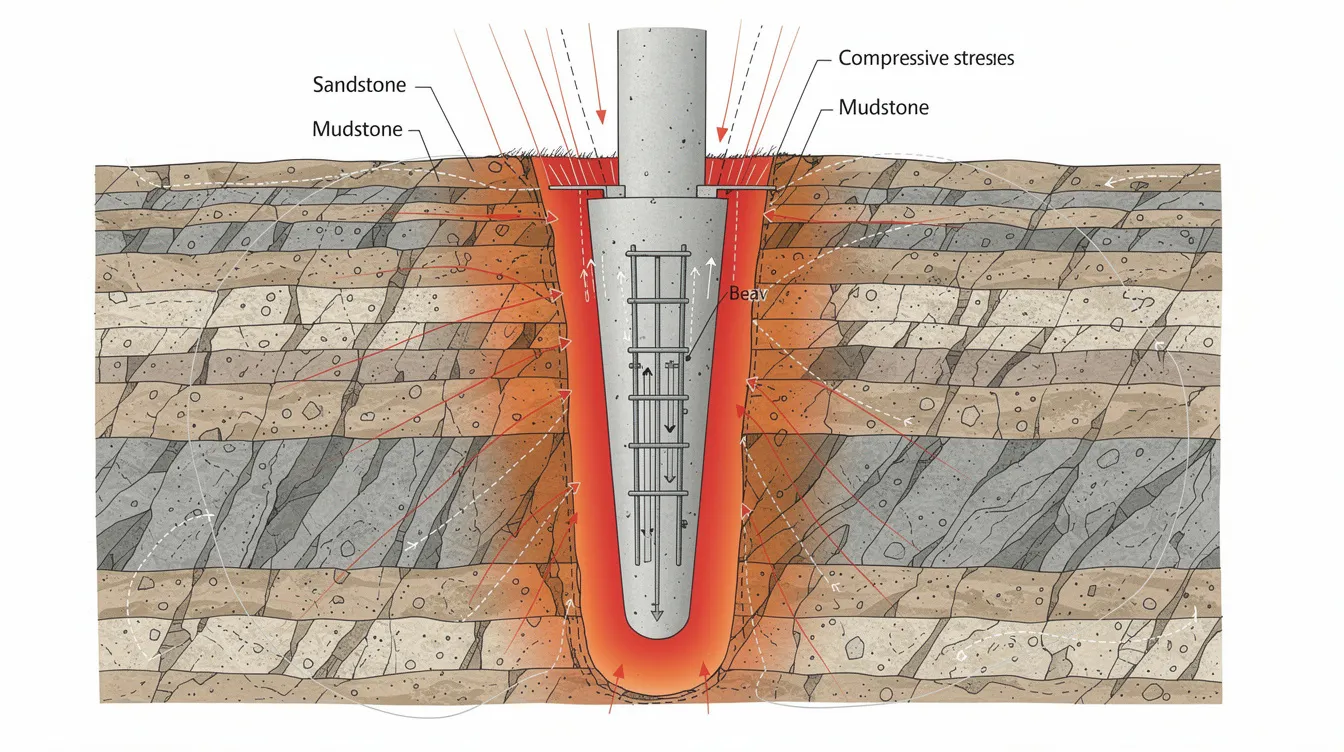
Wedge Stability Analysis Methods
Structural failures in the Jurong Formation can be due to wedge failures along joints and bedding planes – making stability analysis of potential wedge formations one of the most critical aspects of permanent retention design. Discontinuity mapping is critical to ensure stability during excavation in the Jurong Formation, and robust site investigations should include discontinuity surveys covering orientation, spacing, persistence, roughness, and infilling characteristics.
Kinematic analysis begins with collecting joint orientation data from geological mapping of rock cores, borehole televiewer logs, and exposed shaft faces. Stereographic projection techniques then identify critical wedge geometries by plotting joint set intersections against the shaft wall orientation. In the Jurong Formation, the combination of gently dipping bedding planes (up to ~25°) with two sub-vertical joint sets (NS and EW) creates the potential for large wedge blocks, particularly where bedding acts as the basal release surface.
Factor of safety calculations must incorporate both peak and residual shear strength across joints. For permanent retention, minimum factors of safety should be ≥1.5 under static conditions, increasing when water pressure, dynamic loads, or seismic loading are considered. Rock bolt reinforcement contributions to wedge stability should be modeled using both limit equilibrium and numerical methods. The Jurong Rock Caverns project used Phase² and UDEC analyses to demonstrate that calculated vertical displacements and roof stability were controlled by rock mass quality, joint orientation, and the damage factor from blasting – providing a validated framework applicable to shaft design.
Structural Integration Requirements
The interface design between temporary works and permanent structure elements requires careful detailing to ensure load continuity. In many Jurong Formation projects, temporary rock bolts and shotcrete are incorporated into the permanent retention system rather than being treated as sacrificial elements – demanding higher material specifications from the outset.
Load path analysis must trace forces from superstructure through the retention system to the rock socket foundation, accounting for lateral earth pressures from retained soil above rock, water pressures, and back-loads from adjacent structures. In deep shafts, the permanent lining (typically reinforced concrete, sometimes with steel fibre reinforcement) must transfer all loads into the rock mass through a combination of frictional contact, rock bolt anchorage, and end bearing at the socket base. Permanent support systems should be optimized based on excavation depth and rock mass quality – stiffer, more heavily reinforced systems in weak or highly fractured zones; lighter systems where strong, massive sandstone provides reliable confinement.
Key integration principles: socket depth must be determined by rock quality at the actual socket location (not assumed from nearby boreholes); anchor spacing must relate to mapped joint block dimensions; and waterproofing must be continuous across temporary-to-permanent construction joints.
These design principles translate into specific construction procedures and detailing requirements, addressed in the following section.
Permanent Retention System Implementation and Detailing
With design parameters established from geological investigation and numerical modeling, implementation requires precise construction sequencing, quality-controlled anchor installation, and integrated water management – all coordinated to minimize excavation damage and preserve the integrity of surrounding rock.
Rock Bolt Anchor Design and Installation
Permanent rock bolt systems are required in deep excavations where the jointed rock mass cannot sustain long-term stability without reinforcement, particularly across weak mudstone interbeds and through zones where wedge formation is kinematically possible. The design of permanent shafts differs from temporary shafts due to the need for long-term stability, corrosion protection, and resistance to sustained water exposure.
-
Drilling: Holes are drilled to predetermined depth and diameter using rotary percussive methods. In interbedded formations, drill logs must record lithological changes encountered, as bolt anchorage zones must seat in competent rock (sandstone or siltstone with UCS >50 MPa) beyond any weak interbed.
-
Hole preparation: The hole is flushed clean of cuttings using water or compressed air. In wet and unconsolidated condition zones, stabilization of the hole may require temporary casing or thickened grout.
-
Anchor insertion and grouting: Fully grouted bolts (cement or resin) are standard for permanent retention in the Jurong Formation. Bond length must cross weak layers entirely and anchor beyond them – if a 3-metre mudstone interbed exists, the bond zone should extend at least 2–3 metres past it into stronger rock. Grout mix design must account for groundwater chemistry, particularly sulphate content in clay minerals-rich zones.
-
Tensioning and lock-off: Bolts are tensioned to predetermined preload (typically 60–80% of yield) and locked off. Preload values are determined from wedge stability analysis requirements.
-
Corrosion protection: Double corrosion protection (corrugated sheath + cement grout annulus) is mandatory below the water table. In marine-influenced zones near Jurong Island, additional epoxy coating or stainless steel tendon options may be specified.
-
Verification testing: Pull-out tests on a minimum percentage of installed bolts (typically 5–10%) verify anchorage capacity. Results are compared against design bond stresses at the grout–rock interface.
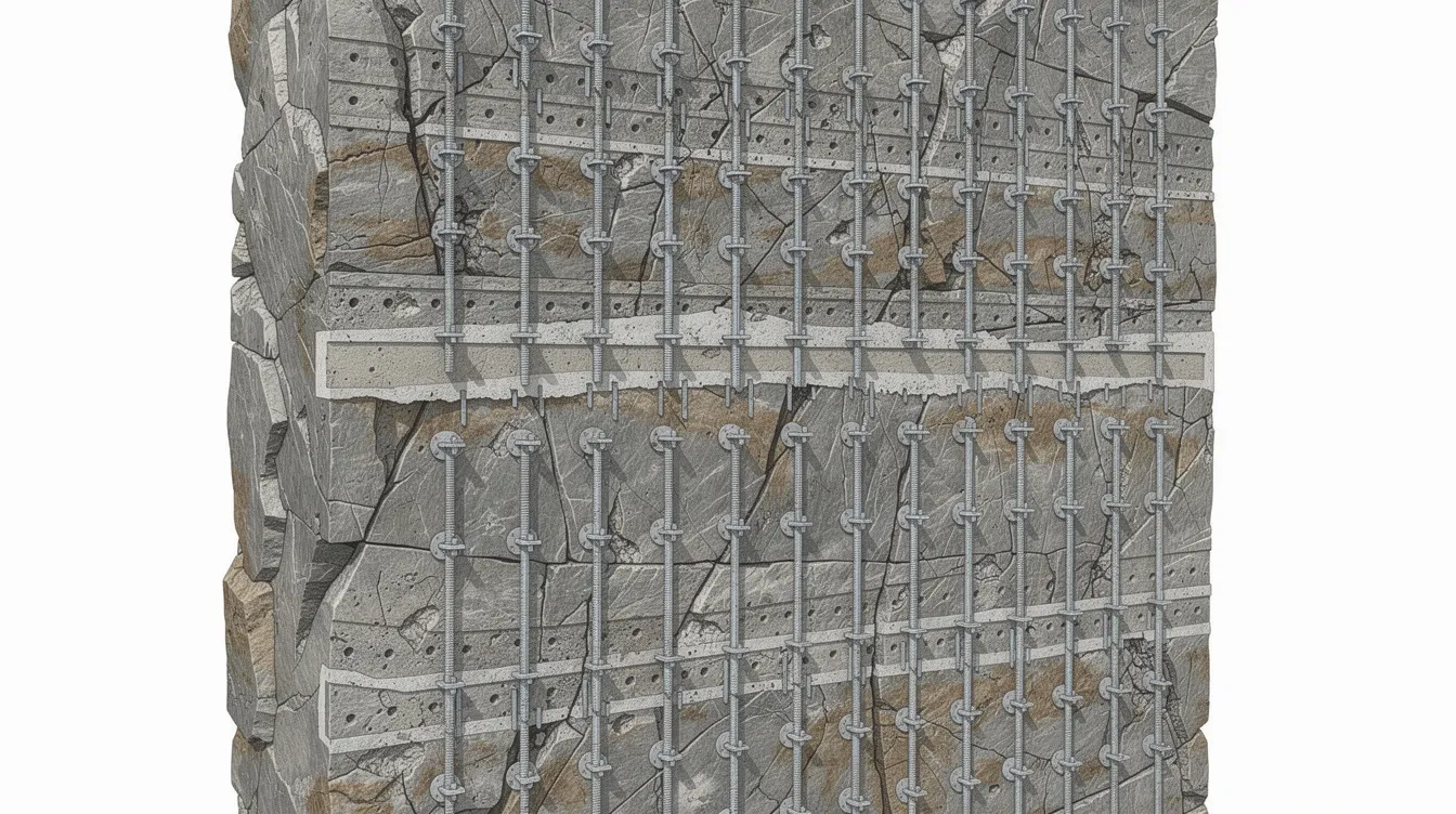
Typical bolt spacing in highly fractured rock masses ranges from 2–5 metres on centres for shaft walls, with closer spacing at intersections of major joint sets. In strong, massive rock, spacing may widen to 4–6 metres.
Construction Sequencing and Monitoring
Construction methods must minimize excavation damage to preserve the integrity of surrounding rock. The choice between drill-and-blast and mechanical excavation depends on rock mass quality, shaft diameter, and proximity to sensitive structures.
|
Criterion |
Drill-and-Blast |
Mechanical Excavation |
|---|---|---|
|
Best suited rock type |
Hard rock (UCS >60 MPa); fresh sandstone, limestone |
Weaker sedimentary rock; weathered mudstone/siltstone |
|
Excavation rate |
Higher in competent rock; typical 2–4 m/day advance |
Lower but more controlled; 1–2 m/day |
|
Damage zone |
0.5–2.0 m blast damage zone requiring additional support |
Minimal damage; better preservation of rock mass properties |
|
Vibration impact |
Requires blast monitoring; may affect nearby structures |
Low vibration; suitable near sensitive infrastructure |
|
Cost efficiency |
More economical for large cavern excavation and wide span caverns |
Higher unit cost but fewer remedial works |
|
Typical application |
Underground cavern excavation (JRC used drill-and-blast method) |
Shaft through weathered/transition zones |
The drill-and-blast method is used for large cavern excavations and is standard for competent sections of deep shafts, while mechanical methods are preferred through weathered transition zones. Sequential excavation proceeds in benches of 2–4 metres, with support installed immediately after each bench:
-
Probe drilling ahead of the face to identify water-bearing fractures
-
Pre-grouting if required based on probe results
-
Excavation of bench (blast or mechanical)
-
Geological mapping of exposed faces – engineering geology documentation of discontinuities, lithology changes, water seepage
-
Installation of rock bolts and initial shotcrete layer (50–75 mm)
-
Monitoring readings: extensometers, piezometers, bolt load cells
-
Final shotcrete layer and permanent lining installation
Dynamic monitoring is essential to adjust designs based on geological variability during construction. Instrumentation includes multi-point borehole extensometers, vibrating wire piezometers, strain gauges in bolts, and convergence measurement arrays. For shafts deeper than 50 metres (such as the Jurong Rock Caverns access shafts at up to 150 metres deep), monitoring data must be reviewed in near-real-time to trigger design adjustments if deformation or water inflow exceeds alert levels.
Water Inflow Management Systems
Groundwater control is crucial for stability in the Jurong Formation, and permanent retention systems should include drainage paths to manage groundwater throughout the design life. Excavation in the Jurong Formation requires extensive ground treatment, particularly where fractured zones or limestone solution features are encountered.
Pre-excavation grouting: Probe drilling ahead of the shaft face identifies water-bearing fractures. Cementitious or chemical grouts are injected to seal major joints and fissures before excavation exposes them. In worst-case fracture zones, inflows of thousands of cubic metres per day are possible without pre-treatment.
Permanent drainage integration: Embedded drainage layers behind the permanent lining, weep holes at regular intervals, and drainage channels collecting to sumps form an integrated system. The drainage path must be designed to relieve hydrostatic pressure without allowing progressive erosion of joint infill or migration of clay minerals from muddy sediments into drainage elements.
Waterproof lining systems: For permanent shafts, a composite system of sprayed waterproof membrane between initial and final concrete linings is standard. The membrane must accommodate the calculated vertical displacements and lateral deformations predicted by numerical models without tearing or debonding.
Long-term monitoring: Piezometers behind the permanent lining track water pressure build-up. Leakage rate monitoring confirms waterproofing integrity. Any increase in seepage rates triggers investigation – potential causes include deterioration of grout curtains, new fracture propagation, or membrane damage.
These implementation details address the design intent but must anticipate the challenges that inevitably arise during construction in this geologically complex formation.
Common Challenges and Solutions
Deep excavation in the Jurong Formation consistently produces conditions that deviate from design assumptions. The following challenges represent the most frequently encountered issues, with proven solutions drawn from major projects including the Jurong Rock Caverns and DTSS Phase 2.
Variable Rock Mass Quality
Rock quality can change significantly over short distances in the Jurong Formation – a single shaft bench may expose fresh sandstone (UCS >80 MPa) adjacent to completely weathered mudstone (UCS <5 MPa). This variability challenges every aspect of retention design, from rock bolt anchorage to lining thickness.
Solution: Adopt adaptive design frameworks with pre-defined response protocols for different rock classes encountered. Dense ground investigation with boreholes at close spacing (typically 10–15 m centres for shafts), supplemented by geophysical surveys (seismic refraction/reflection) to identify lateral strength variations between boreholes. Rock socket depths should be specified as “minimum embedment into Grade II or strong Grade III rock” rather than fixed absolute depths, allowing adjustment based on actual conditions revealed during excavation. In situ tests including pressuremeter and plate load tests supplement laboratory data from rock cores. For the BCA structural submission process, design documentation should include contingency details showing how the design accommodates the range of rock classes expected.
Unexpected Water Inflow
Limestone beds, faults, or previously unmapped fracture systems may produce sudden high-volume inflows that exceed dewatering capacity and threaten shaft stability. Localized high-pressure groundwater can threaten shaft stability in the Jurong Formation with minimal warning.
Solution: Emergency grouting procedures using fast-setting chemical grouts (polyurethane or silicate-based) for immediate flow control, followed by systematic cement grouting once flow is reduced. Probe drilling ahead of every excavation bench (minimum 6 metres ahead) is non-negotiable in limestone-bearing zones. Fallback measures include temporary steel cover plates bolted to the shaft wall to contain inflow while grouting proceeds from the surface or from adjacent access tunnels. Redundant dewatering capacity (minimum 150% of predicted peak inflow) must be available on-site. In the JRC project, a water curtain system maintained hydraulic containment by injecting water into outer rock to ensure pore pressures exceeded internal pressures – a principle adaptable to shaft design where external groundwater control is required.
Construction Access and Safety
For excavations exceeding 50 metres depth – particularly shafts approaching the 150-metre depths of the Jurong Rock Caverns – logistics, ventilation, emergency egress, and worker safety become governing constraints. Stand-up time in weak rock is limited, requiring rapid support installation.
Solution: Dedicated shaft cage systems for personnel and material transport, with redundant hoisting mechanisms. Ventilation systems must provide minimum 0.3 m³/s fresh air per person working at depth. Emergency ladderways independent of mechanical systems are mandatory under Workplace Safety and Health (Construction) Regulations. Construction platforms at maximum 10-metre vertical intervals provide staging for support installation and emergency refuge. For shafts in the Jurong Formation, qualified person supervision must include a geotechnical engineer with authority to halt excavation if mapped conditions deviate significantly from design assumptions. Shotcrete quality control requires accelerated strength testing (minimum 1 MPa at 8 hours for initial support adequacy) given the limited stand-up time in weak interbeds.
These challenges reinforce the necessity of the integrated design approach summarized in the conclusion.
Conclusion and Next Steps
Permanent retention design for deep excavation shafts in the Jurong Formation is fundamentally an exercise in managing geological uncertainty while engineering for long-term performance. The integration of rock socket capacity analysis (calibrated to lithology-specific UCS values across interbedded sandstone, siltstone, and mudstone), wedge stability assessment (using kinematic analysis of mapped discontinuities with minimum FOS ≥1.5), and robust water management (pre-grouting, permanent drainage, waterproof membranes) defines the core design framework. The rock mechanics principles demonstrated in landmark projects – particularly the Jurong Rock Caverns, which provide 1.47 million cubic metres of storage at up to 150 metres deep at a project cost of approximately S$950 million, and the earlier Underground Ammunition Facility (UAF) completed in 2008 as Singapore’s first major rock cavern that freed up 300 hectares of surface land for development – validate the feasibility of permanent underground excavations in this formation.
The Jurong Rock Caverns support Singapore’s petrochemical sector by providing underground storage that reduces the need for extensive safety buffer zones, demonstrating how underground caverns on Jurong Island deliver strategic value despite building underground costing about 30% more than surface facilities. The JRC created 1.47 million cubic metres of storage capacity through cavern development at depths requiring mastery of the exact design principles covered in this article – rock engineering practice applied to Singapore’s sedimentary Jurong Formation at its most demanding scale. The UAF project freed up 300 hectares of surface land, confirming that well-designed permanent retention in rock delivers enduring infrastructure value. For context, while Jurong Formation rocks harder than mudstone can approach significant strengths, the Bukit Timah Granite – a different geological unit – has an unconfined compressive strength of 160 MPa, illustrating that design parameters must always be formation-specific.
Immediate actionable steps:
-
Commission comprehensive geological investigation including minimum 3 boreholes per shaft location, with continuous coring, UCS/PLI testing at 1-metre intervals, discontinuity logging, packer permeability tests, and groundwater monitoring over at least one wet/dry season cycle
-
Perform preliminary numerical modeling using continuum (FEM) and discontinuum methods to establish rock mass modulus, stress distribution, and potential failure mechanisms before finalizing retention system geometry
-
Prepare regulatory submissions including BCA structural plan approval and, for Jurong Island projects, JTC plan consent – both requiring demonstration of adequate rock mass classification, stability analysis, and construction monitoring plans
-
Develop adaptive design protocols with pre-defined response actions for different rock classes, water inflow rates, and deformation thresholds encountered during construction
-
Engage an accredited checker early in the design process for independent verification of retention system adequacy, particularly for shafts exceeding 30 metres depth
Related topics worth exploring include BIM modeling applications for underground rock engineering visualization, civil and structural design service integration for above-ground/below-ground structural continuity, and structural assessment protocols for completed permanent retention installations requiring periodic inspection.
Additional Resources
-
Singapore Standard CP4:2003 – Code of Practice for Foundations, including weathering classification for Jurong Formation, rock bearing values, rock mass classification approaches (Approach 2 and 4), and socket design guidelines
-
BCA Guidelines on Identification of Rock During Bored Piling Works (GeoSS) – Point load test criteria, specimen frequency requirements, UCS/PLI correlations, and rock stratum identification procedures
-
TR26:2010 Technical Reference for Deep Excavation – LTA general guidelines supplementing site-specific geotechnical requirements
-
Recommended testing protocols for rock socket capacity verification: Minimum UCS testing at 1-metre intervals through socket zone; PLI testing on all recovered core; at least 2 full-scale load tests per shaft; pull-out tests on 5–10% of permanent rock bolts; packer tests at 3-metre intervals for permeability characterization
-
Key research references: Shirlaw, Hencher & Zhao (2000) on tunnelling in weathered rocks of the Jurong Formation; Rueda et al. on engineering properties and mechanical properties of Jurong Formation rocks compiled from extensive laboratory test programs; research contributions from Nanyang Technological University and the defence science community on physical properties and geological properties of the formation, with age determination studies refining the age range assigned to the formation’s constituent units, supported by collected fossil species and previous finding data that fall within the same age range