
Introduction
Contiguous bored pile walls achieve permanent retention status when integrated with cast-in-place reinforced concrete facing walls, drainage membranes, and shotcrete applications – converting what begins as a deep excavation support system into a lasting structural element of the building envelope. In Singapore’s dense urban environment, where basement construction routinely pushes below multiple levels and permanent underground structures such as a cut and cover tunnel demand both retention and watertightness, CBP walls offer a cost-effective alternative to diaphragm wall systems while delivering the structural performance required for long-term use.
This article covers the full technical pathway for justifying CBP walls as permanent retention systems: structural liner design and implementation, waterproofing integration strategies, connection and load transfer detailing, and the regulatory compliance framework under Singapore’s BCA submission process. It does not address temporary-only retention design or secant pile wall systems, which involve fundamentally different construction and design approaches. The focus is on permanent basement walls and other underground developments, including coordination implications for the excavation plan, where design, waterproofing, and authority compliance must work together over the intended service life.
The target audience includes structural engineers designing permanent basement walls, developers evaluating retaining structure options for underground developments, contractors coordinating CBP installation with liner and waterproofing works, and professionals preparing BCA structural plan submissions for permanent retention solutions in Singapore. For these teams, the issue is not only initial excavation support but whether the permanent wall can transfer load reliably, control groundwater, satisfy durability requirements, and pass approval without redesign during construction.
In short: permanent contiguous bored pile CBP walls become effective permanent retention structures when integrated with structural liners such as cast-in-place reinforced concrete facing walls or shotcrete, combined with comprehensive waterproofing through membranes, integral admixtures, and drainage systems to achieve watertightness and meet Singapore building standards including SS 637:2018 and SS 544.
After reading this article, you will understand:
- How contiguous bored pile walls transition from temporary support to permanent retaining walls through structural liner integration
- Design requirements for cast-in-place concrete facing systems and shotcrete applications in permanent CBP walls
- Waterproofing strategies including membrane systems, integral admixtures, and drainage integration
- BCA submission and approval strategies for permanent CBP retention systems
- Practical solutions for common construction challenges including joint sealing, sequencing, and quality assurance
Understanding CBP Wall Permanent Retention Systems
Contiguous bored pile walls consist of bored piles installed side by side with small gaps typically ranging from 50 mm to 150 mm between adjacent piles. Contiguous bored piles are typically 700 mm in diameter with center-to-center spacing often at 750 mm, though larger diameters – such as the 1.5 m piles at 1.7 m centre-to-centre used in a documented 35 m deep excavation in Singapore’s Jurong Formation – are common for deeper retaining walls. CBP walls are commonly used in urban areas where space is constrained, and they have evolved significantly from purely temporary lateral earth support systems to fully permanent retention solutions in Singapore’s construction industry.
The evolution toward permanent applications has been driven by cost considerations – constructing a separate permanent basement wall inside a temporary retention system doubles material use – and by demonstrated performance in projects like the SMU campus development where contiguous pile retaining walls were adopted because diaphragm wall construction proved impractical through boulder-laden stratum. Structural liners are used to transition CBP walls into permanent structural elements, transforming the pile arrangement into a load-bearing, waterproofed wall suitable for occupied basements, subway stations, road underpasses, a cover tunnel, and other tunnel structure applications. For cut and cover works, the CBP system may also need to support the cover tunnel structure.
Permanent vs Temporary CBP Applications
The fundamental difference between temporary and permanent contiguous bored pile walls lies in design life, material specifications, and structural integration requirements. Temporary CBP applications – typically supporting staged excavation for months to a few years – can tolerate some water seepage through pile gaps, use lower concrete durability grades, and rely on temporary ground anchors or struts that will be removed. Permanent CBP walls, by contrast, must perform for the full intended working life of 50 to 100 years, resisting earth pressure, hydrostatic loads, and environmental degradation over decades.
For permanent applications, concrete specifications must comply with SS 544 durability requirements for the relevant exposure class. Concrete cast directly against soil demands a minimum nominal cover of approximately 40 mm after accounting for construction deviations, as specified in LTA Engineering Group Documents E/GD/09/106/A2. Early-age thermal cracking and shrinkage must be calculated and mitigated, with crack widths controlled to less than 0.3 mm to limit water ingress. These requirements directly feed into BCA structural plan submissions, where permanent retention walls must demonstrate full compliance with building codes for durability, waterproofing, and structural adequacy.
Permanent CBP walls can be used in deep basements, subway stations, and road underpasses. Contiguous bored pile walls can be tied back with permanent soil anchors or supported by permanent strutting integrated into the building frame structure. A typical contiguous bored pile wall length is around 14 m, though deeper installations are routine – the maximum height of excavation can reach 20 meters in challenging projects, and the Jurong Formation case study documented CBP piles extending to toe embedments of 4 m into rock or 19 m into stiff residual soil.
Structural Integration Components
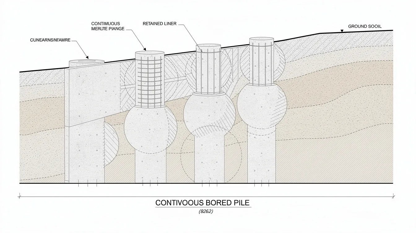
The installation of a capping beam ties the pile heads together in a CBP wall, creating a unified retaining structure that distributes loads across individual wall elements. Below the capping beam, the cast-in-place reinforced concrete facing wall or shotcrete liner connects to the CBP piles through overlapping reinforcement, embedded plates, or post-installed anchors – forming a composite system that handles earth pressure, water pressure, and surcharge loads from adjacent structures and adjacent buildings.
CBP walls rely on the soil arching effect for stability between pile gaps, but for permanent applications this mechanism alone is insufficient. Liners help prevent soil loss and erosion behind pile gaps, while secondary structural liner walls can provide a smooth internal finish suitable for occupancy. The relationship between CBP piles, structural liners, and the overall building structural system must be modelled – typically using 2D or 3D finite element analysis – to verify load paths, deflection limits, and long-term performance under drained and undrained conditions.
The structural liner, whether cast concrete or shotcrete, must accommodate both the permanent earth pressures and the hydrostatic pressures from pore water pressures acting on the wall. Groundwater management is critical when using CBP walls in construction, particularly in Singapore where shallow water tables have been observed at 0.7 to 1.0 m below the ground surface level in documented projects, and site investigation and monitoring data consistently confirm the need to design for hydrostatic loading from near the top of the excavation to almost the full excavation depth in such conditions.
Structural Liner Design and Implementation
Structural liner selection for permanent CBP walls depends on available space between the pile face and the building’s usable area, the exposure conditions, cost constraints, and the waterproofing strategy. The two primary options – cast-in-place reinforced concrete facing walls and shotcrete liners – serve different project conditions but must both achieve the same outcome: a durable, watertight, structurally integrated permanent wall.
Cast-in-Place Concrete Facing Systems
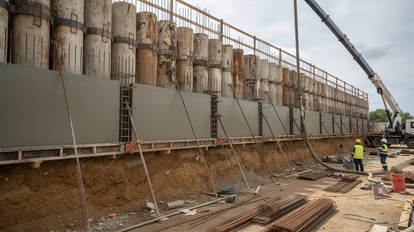
Cast-in-place reinforced concrete facing walls are constructed by erecting formwork in front of the CBP pile face, placing reinforcement that ties into the pile reinforcement, and pouring concrete to create a continuous structural wall. This approach produces a predictable, high-quality finish with excellent control over concrete cover, reinforcement placement, and surface regularity – making it the preferred substrate for bonded membrane waterproofing systems.
Reinforcement detailing for the concrete facing must address connection to the CBP pile reinforcement through overlapping bars, welded embedded plates, or cast-in dowels that ensure composite action between the facing and the piles. The facing reinforcement itself must be designed for the permanent earth pressures and hydrostatic loads, with spacing and bar sizes determined by structural analysis. Concrete cover must comply with exposure class requirements – for basement walls in contact with groundwater, this typically means a minimum durable cover of 40 mm or more, with supplementary cementitious materials (silica fume, fly ash) reducing permeability and improving long-term durability in Singapore’s tropical environment.
The concrete specification for permanent facing walls typically requires strength class C32/40 or higher, a low water-to-binder ratio to minimise permeability, and may include hydrophobic pore-blocking or crystalline admixtures as integral waterproofing. Construction joints in the facing wall require waterstops – PVC or hydrophilic strips – to prevent water migration along joint planes. The SMU campus project demonstrated this approach: where space was available in front of the CBP wall, a waterproofed reinforced concrete deck and facing wall was constructed, providing both structural capacity and a clean finished surface for the basement.
Shotcrete Applications and Specifications
Where space constraints prevent formwork erection – a common condition in urban deep excavation projects – shotcrete applied directly to the CBP pile face serves as the structural liner. Shotcrete (wet-mix or dry-mix) is pneumatically projected onto the pile surface, building up thickness in layers with embedded reinforcement mesh or steel fibres providing structural capacity.
Quality control for permanent shotcrete liners is substantially more demanding than for temporary applications. Thickness must meet structural design requirements at every point, which means careful monitoring given the irregular CBP pile face. Surface planeness and finish must be specified and verified, particularly where waterproofing membranes will be applied over the shotcrete. The use of spray-applied waterproofing systems can be effective for CBP walls where shotcrete provides the substrate – these systems conform to the irregular surface geometry while maintaining waterproofing continuity.
Shotcrete mix design for permanent liners should incorporate integral waterproofing admixtures where the project waterproofing strategy relies on structurally integral protection rather than separate membranes. The SMU project adopted this approach in constrained CBP sections: modified shotcrete containing CALTITE or similar hydrophobic admixtures was applied directly to the pile face, eliminating the need for separate membrane installation and protection layers – a significant advantage beneath heavily landscaped podium areas where root penetration and construction equipment loads could damage conventional membrane systems.
Curing of shotcrete liners requires particular attention in Singapore’s high-temperature, high-humidity environment. Inadequate curing leads to shrinkage cracking, reduced impermeability, and compromised long-term durability. Reinforcement integration – whether welded mesh or fibre reinforcement – must achieve minimum cover from the exposed shotcrete surface to protect against corrosion over the design life.
Connection and Load Transfer Details
The structural connection between CBP piles and the facing system is the critical detail that determines whether the composite wall performs as designed. Connection methods include:
- Overlapping reinforcement: Pile cage reinforcement extended beyond the pile face and lapped with facing wall reinforcement – provides direct structural continuity but requires coordination during pile construction
- Embedded steel plates: Plates cast into pile heads or pile faces, welded to facing reinforcement – allows sequential construction with clear load transfer paths and can serve as an embedded pressure element where the liner-to-pile connection must transfer concentrated forces without overstressing local concrete
- Post-installed anchors: Drilled and grouted anchors connecting the cured facing to the pile concrete – most flexible for construction sequencing but requires verification of anchor capacity, including the properties of the surrounding bond soil, and durability
- Tie beams and pile caps: Structural elements at pile heads connecting piles to the facing wall and integrating with the building’s floor slab system – provides robust load transfer at floor levels
Load transfer through the integrated CBP-liner system must account for lateral earth pressures, hydrostatic water pressure, surcharge loads from adjacent buildings and traffic, and any asymmetric loading conditions. Support layout, including anchor or tie locations, also needs appropriate horizontal spacing to control loads and serviceability. Maximum wall deflection must be controlled within limits established in the ERSS plan – for permanent walls, these limits are typically stricter than for temporary retention to protect surrounding structures foundation integrity and avoid unwanted consolidation settlements in adjacent ground.
In documented performance monitoring, maximum wall deflection of SBPW and CBPW was recorded at 7.3 mm in one Kuching City project where excavation depth averaged about 10 m, while maximum wall deflection occurred at 14.3 mm during the final excavation stage in more challenging conditions. These values inform design verification and assessment of overall excavation performance for permanent retention systems.
Comprehensive Waterproofing Integration
Waterproofing is usually required for permanent CBP walls due to gaps between piles – the 50 mm to 150 mm spaces between contiguous piles create direct pathways for water ingress that must be sealed. Effective detailing is essential for waterproofing continuity in CBP wall construction, and the waterproofing strategy must be determined early in design because it directly affects structural liner selection, construction sequencing, and material specifications. Singapore’s SS 637:2018 provides the governing framework, recognising three water-tightness methods: tanked protection (continuous waterproofing barrier), structurally integral waterproofing (the concrete structure itself resists water penetration), and drained protection (cavity and drainage systems collecting water).
Primary Waterproofing Systems
Primary waterproofing is essential for all permanent CBP walls where the basement environment must remain dry – which includes virtually every occupied basement, underground car park, and service corridor. The choice between membrane-based and integral systems (or a combination) depends on hydrostatic pressure levels, construction access, long-term maintenance feasibility, and cost.
Membrane application for permanent CBP walls follows a systematic process:
- Substrate preparation: The CBP pile face – or more commonly the shotcrete or cast concrete facing – must be clean, sound, and free of loose material, laitance, and form tie points. Rough CBP pile surfaces generally require shotcrete smoothing or RC facing to provide a regular substrate suitable for membrane adhesion
- Priming: Apply manufacturer-specified primer to prepared substrate, ensuring coverage of all surfaces including recesses and irregularities
- Membrane installation: Apply bonded membrane sheets or spray-applied membrane to the primed surface, maintaining specified overlap widths at all seams (typically 75–100 mm), ensuring full adhesion without air pockets, and sealing all penetrations with compatible sealant systems
- Seam and detail sealing: All overlaps, corners, penetrations, and terminations require additional treatment – typically reinforcing strips, injection ports, or hydrophilic sealant bands
- Quality assurance testing: Under SS 637:2018, ponding test duration has been extended from 12 to 24 hours to verify membrane integrity. Documentation must include waterproofing datasheets, as-built drawings, photographs, and delivery records of waterproofing materials
- Protection layer installation: Geotextile or drainage board protection applied over the membrane before any backfilling operations, preventing mechanical damage from construction equipment or soil backfill
For blind-side applications where waterproofing must be installed before the structural liner, systems like PREPRUFE SCS Plus – comprising a polymer mesh, plastic film, geotextile backing, and injection ports for hydrophilic grout – are installed against the excavation face or temporary retention before shotcrete is applied. Post-construction grout injection through the ports seals any voids or cracks that develop during curing.
Waterproofing membranes can be applied to reduce water ingress through pile joints, but membrane performance depends critically on adhesion quality and seam integrity. Projects with high hydrostatic pressure from shallow groundwater tables – groundwater level was generally encountered at 0.7 to 1.0 m depth in multiple Singapore-region projects – demand robust membrane systems with verified adhesion under sustained pressure.
Secondary Protection Methods
| Waterproofing Approach | Performance Characteristics | Cost Factors | Maintenance Requirements | Best Application |
|---|---|---|---|---|
| Bonded membrane (positive side) | High impermeability; proven long-term performance under hydrostatic pressure | Higher material and labour cost; requires protection layer | Low if properly installed; repair requires excavation access | High water table; occupied basements requiring dry conditions |
| Blind-side membrane (e.g. PREPRUFE SCS Plus) | Installed before liner; injection ports allow post-cure sealing | Moderate material cost; specialist installation | Injection ports allow remedial grouting without excavation | Space-constrained sites; shotcrete liner applications |
| Integral waterproofing admixtures | Embedded protection; no membrane to damage; self-healing of microcracks (crystalline types) | Lower installation cost; higher concrete material cost | Minimal – protection is within the concrete matrix | Landscaped podium areas; where membrane protection is impractical |
| Crystalline admixtures (e.g. Xypex) | Reacts with moisture to fill capillary pores and microcracks; water penetration ≤ 10 mm achieved in tests vs 15 mm specification | Moderate admixture cost | Self-healing capability reduces maintenance | Combined with membrane at joints; RC facing or shotcrete |
| Drainage membrane systems | Reduces hydrostatic pressure; collected water directed to drains | Moderate cost; requires pump maintenance | Regular inspection of drains and pumps; filter replacement | Sites with very high or variable groundwater; as secondary protection behind primary membrane |
Synthesis: Most permanent CBP wall projects in Singapore adopt a combined approach. For example, the shopping mall and office complex project used Xypex Admix in the CBP skin wall concrete, Xypex Concentrate coat at joints between the CBP and raft slab, and shotcrete facing – achieving water penetration of approximately 5 mm (Concentrate) and 10 mm (Admix) against a specification limit of 15 mm. This layered strategy addresses the different failure modes: membranes protect joints and interfaces, integral admixtures protect the concrete mass, and drainage systems manage residual hydrostatic pressure.
Drainage System Integration
Drainage integration is essential for reducing hydrostatic pressure on permanent CBP walls and managing the inevitable small quantities of moisture that penetrate any waterproofing system over its service life. The Jurong Formation CBP wall case study demonstrated how weepholes installed between piles to lower the water table significantly reduced lateral loads on the retaining structure – an approach that can be adapted for permanent walls using controlled drainage paths, particularly where permeable gravel layers or gravelly sand layers are present behind or below the wall and groundwater movement can be more pronounced.
Drainage membrane installation must be coordinated with the CBP wall construction sequence: drainage board or cavity drain membrane is typically placed between the waterproofing membrane and the structural liner, collecting any water that penetrates the primary barrier and directing it to floor-level collection channels connected to sump pumps. Groundwater monitoring included weekly measurements of water standpipes in documented projects, with survey-based checks using topographic measure points, and groundwater levels were monitored using vibrating wire piezometers to verify that drainage systems performed as designed during and after construction. Some projects also encounter a siltstone bedrock layer below the soil profile, which can affect long-term drainage assumptions and seepage behaviour.
Connection details between wall drainage systems and the building’s overall waterproofing strategy – including base slab drainage blankets, floor sump systems, and storm drainage outlets – must be designed as an integrated system. Groundwater drawdown was observed during excavation activities in documented cases, and permanent drainage systems must be sized for the long-term steady-state groundwater condition rather than the temporarily drawn-down construction-phase condition, with design reflecting soils that show relatively high permeability values where drainage inflows may persist.

Common Challenges and Solutions
Permanent CBP wall projects with integrated liners and waterproofing consistently encounter three categories of challenges: construction sequencing conflicts, water ingress at pile joints, and regulatory approval complexity. Addressing these proactively during design – rather than reactively during construction – is essential for project success.
Construction Sequencing Conflicts
The construction sequence for permanent CBP walls involves multiple interdependent activities: pile installation, excavation stages, structural liner construction, waterproofing application, protection layer installation, and backfilling. Each stage can damage or compromise the previous one if not properly coordinated.
Solution: Develop a detailed construction methodology statement that maps each activity against its predecessors and successors, with hold points for quality inspection, and ensure the sequencing documents align with the project cover structure plan where the CBP wall forms part of a staged permanent works system. Waterproofing must not be applied until the substrate (shotcrete or RC facing) has achieved adequate cure and surface preparation – but must be completed before any backfilling or subsequent concrete pours that would prevent access. For blind-side systems, the membrane goes in before the liner; for bonded systems, the membrane goes on after. Protection layers must follow immediately after membrane installation to prevent damage from subsequent works. CBP walls serve as temporary support during excavation and as a permanent structural wall, meaning the transition from temporary to permanent function must be explicitly planned in the temporary works design, with coordination to the overall cut and cover sequence where relevant. This coordination should identify the excavation basement level at which the permanent liner, waterproofing, and any ground improvements are introduced.
Water Ingress at CBP Joints
The gaps between contiguous piles represent the most vulnerable points for water ingress in permanent CBP walls. Even with structural liners and waterproofing, poorly treated pile joints can allow water to migrate behind the liner and compromise the entire waterproofing system. In one documented case, ground anchors that punctured through the CBP wall worsened leakage conditions significantly.
Solution: A multi-layered approach addresses joint leakage at multiple levels. First, jet grout columns or cement grout columns installed between piles during wall construction reduce permeability at the source and can also mitigate unexpected effective stress increments caused by groundwater changes around the wall – jet grout columns were designed at 80 cm diameter for stability in one documented project. Second, waterstop strips or hydrophilic gaskets installed at pile joints provide a physical barrier. Third, the structural liner (shotcrete or RC facing) bridges across joints, with the liner’s own waterproofing – membrane or integral – providing the final barrier. Fourth, injection ports cast into the liner allow post-construction grouting to seal any residual leakage paths. For post grouted soil anchors penetrating the wall, special sleeve and sealant details must be specified to maintain watertightness at penetration points.
BCA Submission and Approval Challenges
Justifying CBP walls as permanent retention systems in Singapore requires comprehensive documentation that demonstrates structural adequacy, waterproofing compliance, and long-term durability. Incomplete submissions – particularly those that omit waterproofing details, joint treatment specifications, or durability assessments – risk rejection or extensive revision requests.
Solution: The structural plan submission must include: full structural design calculations showing pile strength, facing liner design (thickness, reinforcement, cover), load transfer mechanisms, and safety factors under earth and hydrostatic pressures; waterproofing strategy demonstrating compliance with SS 637:2018 including membrane type, location, joint details, and ponding test requirements; durability assessment showing concrete mix design, cover adequacy for exposure class, crack width control measures, and curing regime; and a monitoring plan with deflection limits, instrumentation specifications, checks on potential ground movements affecting adjacent buildings, and documentation defining the most critical excavation cross for assessment of nearby building response, with alert/work suspension levels per BCA ERSS guidelines. Including precedent case studies – such as the SMU project or documented performance data from similar installations – strengthens the submission and demonstrates practical feasibility, and where heritage or sensitive assets are involved, the submission should describe the existing masonry museum building and relevant foundation vulnerabilities, including cases where a masonry museum building founded on shallow supports requires added monitoring detail. Foundation descriptions should also distinguish a strip foundation from wall footings where those elements govern movement sensitivity. Engagement of a qualified PE and, where required, an Accredited Checker ensures the submission meets regulatory expectations.
Conclusion and Next Steps
Permanent contiguous bored pile walls are viable and increasingly adopted retention solutions for Singapore’s deep excavation and basement construction projects. The technical pathway is clear: CBP walls transition from temporary support to permanent retaining walls through structural liners – cast-in-place reinforced concrete facing walls or shotcrete – combined with comprehensive waterproofing that addresses both the concrete mass and the critical pile joint interfaces. Contiguous bored piles are often used in urban excavation projects where they offer advantages over diaphragm wall systems in terms of cost and constructability through difficult ground conditions.
Performance data from completed projects confirms the approach works: water penetration values of 5–10 mm against 15 mm specifications, maximum wall deflection values within design limits, and successful long-term operation of waterproofed CBP basement walls in Singapore’s demanding tropical environment. The maximum total displacement under museum building was recorded at 1.3 cm in one project with initial settlement of museum building calculated as 3.5 cm, while excavation caused building settlement up to 98.3 mm in more extreme cases – demonstrating the importance of proper design, monitoring, and ground movement control for nearby structure foundations.
Immediate next steps for engineers and developers considering permanent CBP walls:
- Site assessment: Conduct thorough site investigation including groundwater conditions – groundwater conditions were measured by a series of piezometers in documented projects – soil stratigraphy, including clay deposits where present; the clay deposits range in consistency and strength across a site and should be defined during investigation; and proximity to adjacent structures. The original site investigation comprised borehole data, in-situ testing, and groundwater observation to establish design parameters, and should identify any uncontrolled fill material and the underlying clay layer, with uncontrolled fill material overlying weaker natural strata treated as a particular risk condition, because both affect permanent wall behavior and groundwater control. Dense layers based on SPT results, including any very dense layers, should also be identified because they influence pile behaviour, seepage paths, and support design. The museum building foundation soil should likewise be characterised where adjacent heritage or sensitive structures are present.
- Preliminary design: Select structural liner type (RC facing vs shotcrete) based on available space, soil conditions, and waterproofing strategy. Evaluate ground improvements where weak rock zone or stiff clay layer conditions warrant additional treatment
- Waterproofing strategy: Choose primary system (membrane, integral, or combined) and secondary protection (drainage) based on hydrostatic pressure, exposure conditions, and life-cycle cost; larger underground works such as an excavation tunnel or portal structure may impose additional waterproofing and staging demands. For the Konak Tunnel, the excavation dimensions used to cover excavation area were approximately 60 m × 42 m, with the longest section of the main excavation reaching 155 meters wide – illustrating the scale at which these decisions affect project cost. Support design for a cover tunnel may also require checking each east piled wall row separately where geometry or neighboring loads differ.
- BCA pre-consultation: Engage with BCA early to confirm acceptance of permanent CBP retention approach, clarify submission requirements, and identify any project-specific conditions
- Contractor qualification: Verify contractor experience with permanent CBP wall systems, including shotcrete application, membrane installation, and joint treatment – quality of execution is as critical as quality of design
Related topics for further exploration include pile load testing requirements for permanent CBP piles, ground anchor integration for permanent retention (including the distinction between temporary removable and permanent soil anchors), and long-term structural inspection and monitoring systems for permanent retention structures.
Additional Resources
- SS 637:2018 – Code of Practice for Waterproofing of Reinforced Concrete Buildings: governs waterproofing design, membrane specifications, ponding test requirements (24 hours), and documentation for Singapore projects
- SS 544 – Durability of Concrete Structures: exposure class definitions, concrete cover requirements, and durability provisions for underground structures with intended working life of 50–100 years
- LTA Engineering Group Documents E/GD/09/104/A1 and E/GD/09/106/A2 – minimum concrete cover requirements for concrete cast against soil, deviation allowances, and early-age thermal cracking calculations
- BCA Approved Document – building control standards including ERSS requirements, wall deflection alert levels, and structural plan submission procedures. See the complete guide to BCA Approved Document for current requirements
- Green Mark 2021 Technical Guide – sustainability requirements including water-tightness prerequisites for basement walls and Green Mark points related to waterproofing performance
- AMAN Engineering provides professional engineering services for CBP wall design, BCA structural submissions, temporary works and ERSS design, PE endorsement, and structural inspection for permanent retention structures in Singapore