

Key Takeaways
Deep excavations beside property boundaries require the retaining system, construction sequence, approvals, and monitoring plan to be considered together.
- Permanent tie-back anchors can preserve internal working space but may require rights beyond the site boundary.
- Strutting keeps support within the site, reducing dependence on neighboring land and easement approvals.
- Soil, groundwater, excavation depth, adjacent structures, and utility sensitivity govern movement-control requirements.
- Singapore projects must coordinate engineering submissions with SLA, LTA, and other relevant authority requirements.
- A clear, documented comparison helps the client and stakeholders understand why a support system was selected.
How boundary constraints shape temporary earth-retaining design
An excavation beside a road, railway, building, or narrow property line has little tolerance for an improvised support arrangement. The Earth Retaining Stabilising System (ERSS) must resist lateral soil and water pressures while limiting movement around the excavation. The most suitable arrangement depends on ground conditions, groundwater, depth, construction methodology, and the sensitivity of nearby structures and infrastructure.
Identifying property lines, easements, and underground obstructions
The first task is to establish what the project can occupy and what it cannot. A boundary survey should be coordinated with title information, easement records, existing structures, utility records, and physical detection works. An anchor may be structurally feasible yet unusable if its bonded zone passes beneath a neighboring parcel, road reserve, tunnel, utility corridor, or other protected area.
This information also affects the retaining-wall alignment. A small shift can change the available anchor length, the position of walers, or the clearance needed for drilling equipment. Treating the boundary as a line on a drawing rather than a three-dimensional legal and physical constraint is a common source of late redesign.
Assessing excavation depth, soil conditions, and groundwater
Excavation depth and soil stratification determine the magnitude and distribution of lateral loading. A reliable ground model should account for variable soil properties, groundwater levels, permeability, and possible hydraulic failure mechanisms. Singapore deep-excavation investigations commonly include boreholes, in-situ testing, laboratory testing, and groundwater monitoring, with the investigation detailed enough to capture spatial variability.
The wall and support system must then be checked for ultimate and serviceability limit states. Groundwater can increase pressure, complicate drilling, and influence the choice between a water-tight wall and a system that permits controlled seepage. The temporary design life, often measured in months or a few years, should also be stated rather than assumed.
Understanding movement limits near adjacent structures and utilities
The acceptable movement is governed by what surrounds the site, not only by the capacity of the retaining wall. A robust structure may tolerate more deformation than a brittle utility, heritage building, track system, or sensitive item of equipment. Noise, vibration, dust, restricted access, and the accuracy required at removal or cutting boundaries can be just as influential as structural strength.
Allowable settlement beside excavations in Singapore is often discussed in the range of 10 mm to 25 mm, depending on sensitivity. That range is not a universal acceptance criterion; the project team must establish limits for the actual neighboring assets. Monitoring should measure wall deflection, ground settlement, groundwater behavior, and building or utility response where relevant.
Coordinating SLA, LTA, and other authority requirements
Authority coordination should begin while support options are still open. The submission package may need to address temporary works design, land occupation, traffic or rail interfaces, utility protection, monitoring, emergency access, and the effect of construction stages on partially completed permanent works. The acronym SLA can also refer to unrelated service agreements, as explained in this service level agreement guide, so project records should use clear descriptions when referring to the Singapore Land Authority.
The distinction matters because an approval risk may arise from land rights even when the structural calculations are satisfactory. Other background uses of the acronym, including this historical SLA reference, are unrelated to authority submissions; precise terminology avoids confusion in correspondence and meeting records. A project-specific approval matrix should identify the responsible party, required drawing, submission date, and response condition for each authority interface.
Permanent tie-back anchors: Benefits, limitations, and approval risks
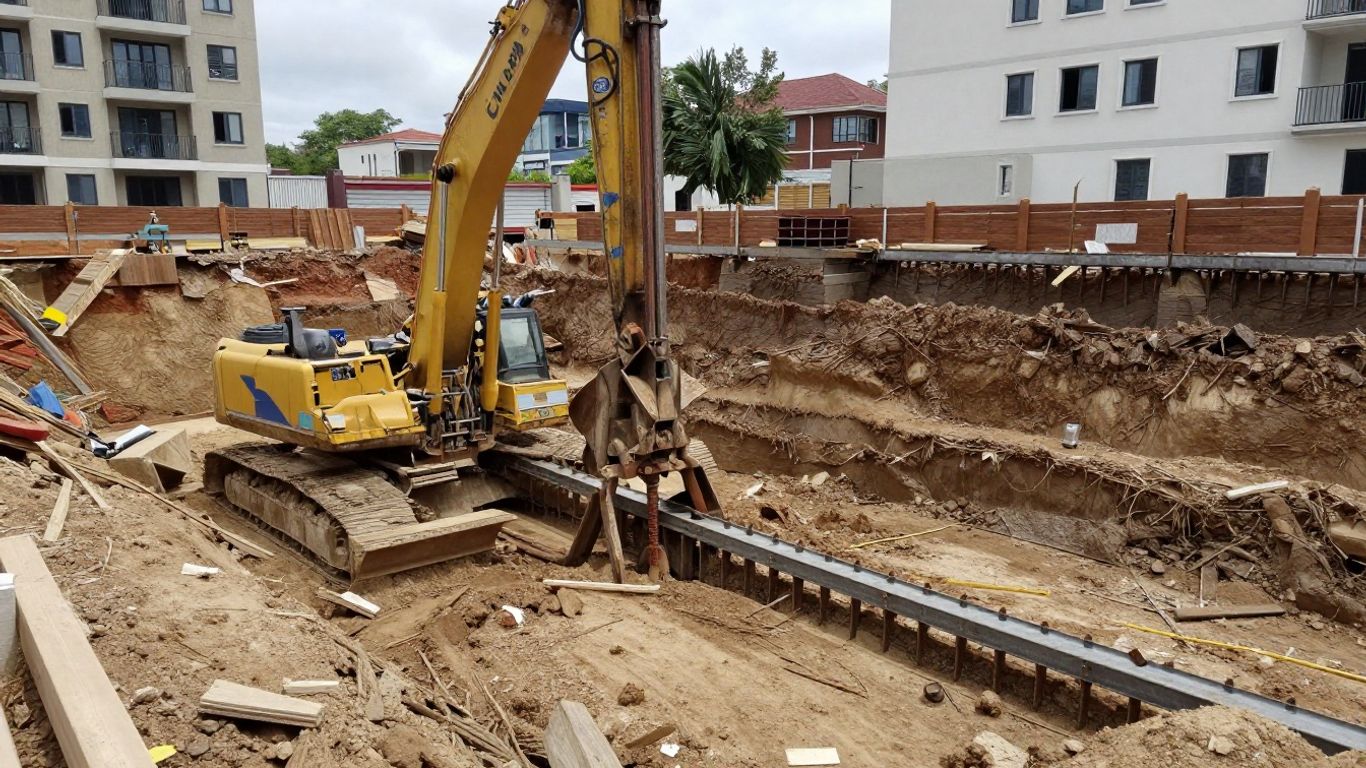
Anchored retaining systems can move support away from the excavation face and leave more room for excavation plant and basement construction. Their apparent simplicity can be misleading, however, because the anchor system extends beyond the wall and may remain in place after construction. The design therefore has structural, geotechnical, land-rights, durability, testing, and monitoring implications.
How anchored retaining systems transfer excavation loads
Ground anchors use pre-stressed tendons to provide active support, usually in combination with a retaining wall. The tendon transfers force through a free length into a bonded zone formed in competent ground beyond the potential failure wedge. At the wall, anchor heads and walers distribute the force into the retaining system.
The arrangement must be checked for tendon capacity, bond, wall bending, waler forces, local bearing, overall stability, and serviceability movement. It must also be coordinated with excavation stages, because stressing an anchor before the wall and surrounding ground are ready can create an unintended load path.
Required anchor zones beyond the site boundary
A permanent tie-back needs sufficient length and ground quality outside the active excavation zone. That zone may lie below neighboring land, a road, reserve, public infrastructure, or an existing basement. Existing and planned underground works must be mapped before drilling, and the possible three-dimensional envelope of each anchor should be reviewed rather than represented only by a plan line.
Where the available zone is uncertain, the designer should test alternative inclinations, levels, and wall positions. The feasibility review should include access for drilling rigs, spoil handling, grout control, tendon installation, and verification testing. If the required bonded length cannot be placed in an acceptable zone, an internal support system may be the more reliable option.
Permanent easements, land rights, and SLA considerations
Permanent anchors commonly require a legal right to occupy or remain beneath land outside the project parcel. The required easement must identify the anchor corridor, access rights, inspection obligations, restrictions on future excavation, and responsibility for damage or removal. Approval from the relevant landowner or authority should be treated as a project dependency, not as paperwork to be completed after design.
For an SLA interface, the submission should distinguish temporary occupation from permanent subsurface rights and show how the anchor geometry relates to the boundary. A technically efficient anchor layout can still fail the programme if the necessary consent is unavailable or subject to conditions that alter the design. The client should receive a clear record of assumptions, outstanding rights, and approval risks.
Corrosion protection, testing, monitoring, and long-term maintenance
Permanent anchors need a durability strategy suited to the ground and groundwater environment. This may include encapsulation, grout protection, corrosion-resistant components, controlled installation, proof testing, and records that allow the installed system to be identified later. The design life and inspection responsibilities should be stated explicitly.
Testing confirms installation quality and load behavior, but it does not replace construction control. Tendon stressing, grout records, anchor coordinates, wall response, and nearby movement should be documented. Long-term maintenance can also become difficult when access points are concealed by permanent works, so the interface between temporary support and the completed basement must be resolved early.
Strutting systems: When internal support is the safer boundary solution
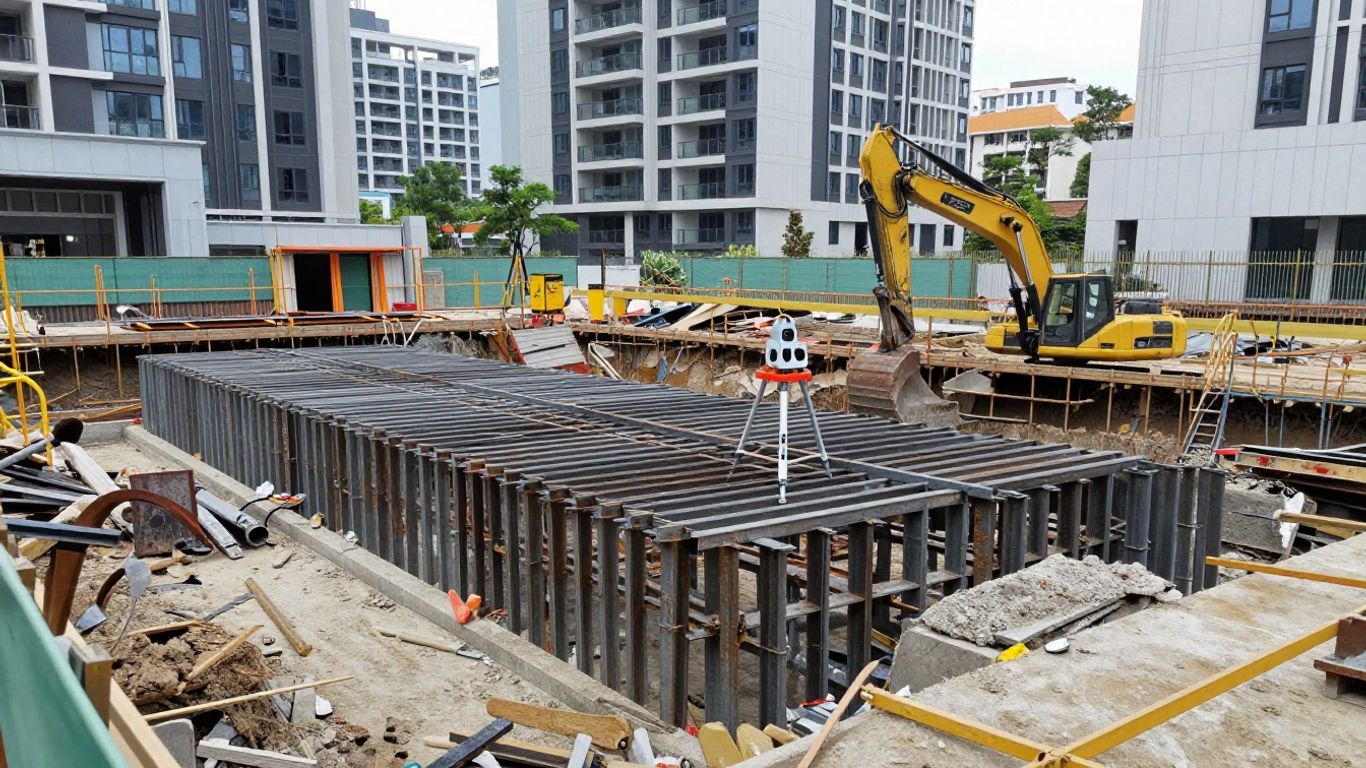
Strutting supports the retaining wall from within the site rather than relying on ground beyond the boundary. Cross-lot struts, walers, rakers, and corner braces can therefore reduce the need for neighboring land rights. They introduce their own constraints: internal steelwork occupies the excavation, affects plant routes, and must be installed and removed in step with excavation and permanent construction.
How walers, rakers, and cross-lot struts provide support
Walers collect and distribute reactions along the retaining wall, while cross-lot struts transfer forces across the excavation. Rakers can brace a wall from a slab, wale, or internal foundation arrangement where a full cross-lot span is impractical. Connections, buckling, bearing, temperature effects, and construction tolerances require the same attention as the primary members.
The support level and spacing are selected through staged analysis. Each excavation lift changes the exposed wall height and the force carried by installed members. The system must remain stable during partial installation, not only after every strut shown on the final drawing is in place.
Avoiding off-site permissions and encroachment complications
The principal boundary advantage of strutting is that its load path remains inside the site. It can avoid permanent anchor easements and reduce dependence on neighboring approvals, although temporary access, road occupation, utility interfaces, and authority conditions may still apply. This is especially useful where property ownership is fragmented or negotiations are uncertain.
Avoiding an external right does not remove the need for coordination. Struts may bear near pile caps, basement walls, ramps, or temporary access zones, so their support points must be checked against the permanent design. Cast-in items, brackets, and embedments should be designed for both temporary and permanent load conditions where they remain in the works.
Managing plant access, excavation sequencing, and workspace
Internal support reduces clear working volume, which can affect excavator reach, truck routes, crane operations, spoil removal, waterproofing, and slab construction. The contractor should model the sequence before selecting member sizes and levels. A support arrangement that is economical on paper may create inefficient handling or unsafe manual work below.
The planning review should address at least these practical questions:
- Can excavation plant reach each working bay after the support level is installed?
- Where will spoil, pumps, reinforcement, and formwork move through the excavation?
- Can permanent slabs or beams be cast without compromising temporary stability?
- What lifting and dismantling method will remove the struts safely?
The answers often lead to changes in strut spacing, temporary openings, ramp locations, or the use of rakers. Construction methodology is part of the engineering decision, not a separate exercise left to site operations.
Controlling deformation through staged installation and removal
Struts should be installed before the wall reaches the movement level associated with the next excavation stage. Preloading may be required to control slack and establish the intended load path, subject to the design assumptions and site procedure. Survey data and instrumentation then provide evidence that the wall and surrounding ground are responding as predicted.
Removal is another critical stage. A strut can be carrying substantial force when a slab or permanent wall is ready to replace it. The replacement element must have achieved the required strength and connection performance before the temporary member is released. Removing several supports in one operation can cause a sudden redistribution of loads and should not be treated as routine dismantling.
Comparing tie-back anchors and strutting systems
Neither system is automatically superior for a constrained excavation. Anchors preserve internal space but extend into ground that may not be controlled by the developer. Struts stay within the boundary but compete with the excavation and basement works for space. A sound comparison therefore considers legality, constructability, movement control, programme, cost, and the consequences of failure or redesign.
Structural performance and excavation movement control
Both systems can provide effective lateral support when designed for the actual soil-structure interaction and construction stages. Anchors provide active restraint through pre-stress, while struts provide internal reaction as the wall moves and the support frame engages. The comparison should include wall stiffness, support stiffness, load redistribution, groundwater, overall stability, and the sensitivity of adjacent assets.
The relevant performance target is not simply the largest calculated capacity. Serviceability movement, angular distortion, vibration, and the reliability of the installation sequence often govern. Monitoring results should be reviewed against design predictions so that the team can respond before a trigger level becomes a damage event.
Construction cost, programme, and equipment requirements
Anchor systems may require specialist drilling, grout handling, stressing, testing, and coordination beyond the site. Strutting may require heavier steel members, lifting operations, temporary connections, and more complicated excavation access. Prices can change significantly once removal, standby time, traffic management, and approval delays are included.
A useful early comparison is shown below. It is a decision aid, not a substitute for project-specific design.
| Consideration | Permanent tie-back anchors | Internal strutting |
|---|---|---|
| Boundary dependency | May require external land rights | Generally contained within the site |
| Internal workspace | Usually more open | Occupied by walers, struts, or rakers |
| Specialist operations | Drilling, grouting, stressing, testing | Steel erection, preloading, and dismantling |
| Long-term issue | Easement, durability, and inspection obligations | Temporary removal and load transfer |
The lowest initial installation cost may not produce the lowest project cost. A delay in obtaining an easement, or a difficult strut-removal sequence, can outweigh a difference in material quantities. The estimate should include the whole temporary works cycle.
Effects on site logistics and basement construction
Anchors are often attractive where the excavation must remain clear for a large basement footprint or where internal columns are difficult to place. They can, however, conflict with neighboring foundations, future utility works, or permanent waterproofing zones. Struts may interfere with slab pours and access but can be arranged around construction stages if the permanent frame is designed to receive load progressively.
The interface between temporary and permanent works deserves a coordinated drawing set. It should show support nodes, openings, embedments, slab strength requirements, removal clearances, and any temporary loads imposed on partially completed permanent elements. Early coordination is usually less disruptive than modifying a basement after steel has arrived on site.
Environmental, safety, and neighboring-property considerations
Drilling, grouting, steel handling, vibration, noise, dust, and spoil disposal all affect the surrounding environment and workforce. The selected arrangement should reflect working-hour limits, confined access, nearby sensitive equipment, and the consequences of an unexpected ground response. Neighboring-property protection also depends on communication, baseline surveys, and a monitoring regime that can distinguish normal construction effects from developing damage.
Risk should be allocated clearly between designer, contractor, landowner, and authority. Where the support system affects a public corridor or neighboring building, the method statement and emergency response should be reviewed with the same seriousness as the calculations.
Design and construction workflow for constrained excavations
A constrained excavation benefits from a workflow that keeps legal, geotechnical, structural, and construction information connected. The design should mature through verified surveys and investigation rather than through assumptions carried forward from a typical detail. Each stage should produce information that can be checked by the next discipline and understood by the authority reviewing the submission.
Completing surveys, ground investigations, and utility detection
Begin with a coordinated boundary and topographical survey, records search, utility detection, trial investigations where appropriate, and a condition survey of neighboring structures. Boreholes and groundwater instruments should be located to test the ground model around the planned wall and anchor zones, not merely within the easiest part of the site.
The investigation should identify soil layers, groundwater regime, obstructions, existing foundations, and potential geohazards. It should also record uncertainty. Where a utility or foundation cannot be confirmed, the support design should include a conservative assumption and a method for verification before excavation proceeds.
Developing the retaining wall and support scheme
The engineer then develops the wall type, embedment, support levels, connection details, drainage or water-stopping provisions, and temporary-to-permanent interfaces. Options may include contiguous bored piles, secant piles, diaphragm walls, sheet piles, or other suitable systems, depending on water control, depth, ground, vibration tolerance, and construction access.
For numerical assessment, PLAXIS Suite can be used for geotechnical finite element analysis of complex soil-structure interaction problems, including soil stratification, groundwater, existing structures, construction staging, dewatering effects, and sensitivity studies. Its use should support engineering judgment and site information rather than disguise uncertainty in the ground model.
Sequencing excavation, support installation, and monitoring
The construction sequence should state the excavation lift, support installation or stressing operation, inspection hold point, monitoring review, and permission to continue. Temporary works can impose loads on partially completed permanent structures, so the permanent works must be checked in their temporary condition before they are used as support.
STAAD Pro provides structural analysis capabilities for assessing the response of affected structures to predicted ground movements, including support settlements and lateral displacements. Used alongside the geotechnical model and monitoring plan, such analysis can help assess induced member stresses, deformation, and potential cracking rather than treating the neighboring structure as an abstract boundary.
Defining trigger levels and contingency measures
Trigger levels should be based on predicted behavior, asset sensitivity, instrument precision, and the time needed to act. The response to an alert should be agreed before work begins, with named decision-makers and preplanned options such as slowing excavation, installing additional support, adjusting dewatering, or temporarily stopping work.
A useful monitoring plan normally identifies:
- The parameter and instrument location to be measured.
- The alert, action, and stop-work levels.
- The measurement frequency during each excavation stage.
- The person responsible for review and notification.
- The contingency action available if the trend worsens.
These details make monitoring operational rather than ceremonial. Trends, rates of change, and correlations between instruments should be reviewed alongside site observations and construction records.
Selecting the right system for an encroachment-constrained project
Selection should be based on the project’s controlling constraint. If external land rights are secure and the excavation requires unobstructed internal space, anchors may be appropriate. If the boundary is legally uncertain, adjacent assets are highly sensitive, or the anchor zone is unavailable, internal strutting may offer a more dependable route even when it complicates construction.
When permanent anchors may be technically and legally viable
Permanent anchors are more likely to suit a project where the ground beyond the wall can be demonstrated to provide a stable bonded zone, the drilling corridor is accessible, and the required easements can be secured before construction. The design must also address corrosion protection, testing, inspection, future restrictions, and the legal consequences of leaving tendons beneath third-party land.
The approval path should be tested against actual geometry and rights documents. A conditional or revocable permission may not provide the same certainty as a registered permanent easement. The client should understand both the engineering benefit and the continuing obligation created by the anchor arrangement.
When strutting is preferable despite internal obstructions
Strutting is often preferable where the boundary cannot be crossed, neighboring owners will not grant rights, or authority approval for permanent subsurface encroachment is uncertain. It can also be advantageous where the project team wants the temporary support to remain entirely under its control. The cost is paid in internal space, sequencing complexity, and lifting or dismantling operations.
Those disadvantages may be manageable if the basement layout has planned support zones or if slabs can be used progressively as permanent props. A slightly less convenient excavation sequence can be preferable to a design dependent on an approval that may arrive late or with restrictive conditions.
Evaluating hybrid systems and temporary anchor alternatives
A hybrid scheme can use different support methods at different elevations or along different boundaries. Anchors may serve an open boundary while struts protect a public corridor or a side with critical neighboring infrastructure. Temporary anchors can sometimes reduce internal obstruction, but their legal, access, testing, durability, and removal requirements still need project-specific review.
The hybrid option should be analyzed as one load path, including transitions between support types. Changes in stiffness can redistribute force into the wall and adjacent supports. The construction sequence must show how each system is installed, monitored, replaced, and removed without creating an unsupported intermediate condition.
Documenting the decision for client, authority, and stakeholder review
The final decision record should explain the constraints, options considered, assumptions, design checks, programme effects, cost basis, approval status, and residual risks. Drawings should show property boundaries, easements, anchor envelopes, strut zones, utilities, monitoring points, and the interfaces with permanent works. This gives the client and reviewing authorities a traceable basis for accepting the proposal.
For teams coordinating detailed steel or concrete interfaces, Tekla Structures supports detailed geometric models and documentation, including temporary structures and construction aids. The model is most useful when it reflects the approved sequence and is coordinated with architectural, structural, and MEP information rather than used only for presentation.
Conclusion
Permanent tie-back anchors and strutting systems can both support deep excavations safely, but they solve different boundary problems. Anchors trade internal freedom for external rights and long-term obligations; struts trade legal independence for tighter construction logistics. A disciplined ERSS workflow—grounded in surveys, investigation, staged analysis, authority coordination, and active monitoring—allows the project team to choose the arrangement that is technically sound and achievable in practice.
Frequently Asked Questions
What is the main difference between tie-back anchors and strutting systems?
Tie-back anchors transfer retaining-wall forces into ground beyond the excavation, while strutting transfers forces through internal members installed within the site. The choice depends on ground, geometry, approvals, and construction sequence.
Why can permanent anchors create approval risks?
Their bonded lengths may extend beneath neighboring land or public corridors. The project may therefore need easements, landowner consent, authority approval, future access provisions, and restrictions on later works.
Does strutting eliminate all boundary-related approvals?
No. Strutting can reduce dependence on off-site land rights, but the project may still require approvals for road occupation, traffic, rail interfaces, utility protection, environmental controls, and monitoring arrangements.
Which system generally provides more internal workspace?
Tie-back anchors usually leave the excavation more open because the main support members are outside the excavation. That benefit must be balanced against drilling access, external rights, and long-term anchor obligations.
How are adjacent structures protected during excavation?
Protection relies on an appropriate wall and support system, realistic movement predictions, staged construction, baseline surveys, instrumentation, trigger levels, and agreed contingency actions. The required limits depend on the sensitivity of each neighboring asset.
Can anchors and struts be used together?
Yes. A hybrid arrangement may use anchors where external rights are available and struts where encroachment is unacceptable. The transitions, stiffness changes, installation stages, and load redistribution must be designed as one coordinated system.
When should authority coordination begin?
It should begin during concept design, before the support arrangement becomes fixed. Early coordination can identify land-rights, utility, traffic, rail, monitoring, and submission requirements that would otherwise cause redesign or delay.