

Key Takeaways
Permanent ERSS design in Singapore requires more than selecting a wall section. It depends on a clear design basis, reliable ground and groundwater information, correct Eurocode 7 design approaches, and coordinated construction-stage controls.
- Define the retaining system, design life, design situations, and movement criteria before sizing members.
- Build characteristic soil and groundwater parameters from a sufficiently detailed site investigation.
- Compare DA1 combination 1, DA1 combination 2, and DA3 using the Singapore National Annex.
- Verify geotechnical, structural, hydraulic, global stability, and serviceability limit states.
- Record assumptions, monitoring responses, construction sequence, and independent review requirements.
Establish the design basis for permanent ERSS in Singapore
A permanent earth retaining structural system must be treated as part of the completed development, not merely as temporary excavation support left in place. The design therefore has to address its intended working life, durability, interfaces with permanent construction, and consequences of movement or failure. In Singapore, the design basis should align the project requirements with SS EN 1997-1 and the applicable Singapore National Annex. Early decisions made here will govern the reliability of every later calculation.
Define the retaining system, design life, and performance requirements
Start by describing the ERSS in functional terms: wall type, retained height, excavation depth, embedment, support levels, and whether the system will remain accessible for inspection or maintenance. A secant pile wall may provide interlocking bored piles and water-tightness for deep excavations, while diaphragm walls are generally suited to very deep excavations exceeding 30 m. Contiguous bored pile walls, sheet piles, and other arrangements may be appropriate where the ground and groundwater conditions permit.
The design life must be stated alongside the exposure, durability, corrosion protection, waterproofing, and inspection assumptions. Performance requirements should include strength, stiffness, watertightness where required, construction tolerances, and acceptable movement at adjacent assets. A permanent ERSS also needs a clear statement of what happens if drainage, anchors, or temporary propping cannot be maintained after the basement is completed.
Identify site constraints, retained ground, and adjacent assets
The investigation and design team should map the excavation boundary against neighboring buildings, roads, rail infrastructure, utilities, drains, property lines, and access routes. The same wall can be acceptable beside an open paved area but unsuitable beside a brittle utility or a movement-sensitive structure. Existing foundations, undocumented obstructions, and restricted working space often control the choice of installation method as much as the soil parameters do.
Record levels, construction easements, plant access, vibration restrictions, noise limits, and the sequence in which adjacent structures can be supported. Singapore’s dense urban setting makes ground movement a central design issue; typical allowable settlement adjacent to excavations may range from 10 mm to 25 mm, depending on the sensitivity of nearby structures and utilities. Those values should be confirmed for the actual project rather than copied as universal limits.
Confirm the applicable SS EN 1997-1 clauses and Singapore National Annex parameters
The calculations should identify the relevant SS EN 1997-1 provisions for retaining structures, limit states, actions, soil parameters, groundwater, and verification. The Singapore National Annex may modify or specify values used in the design, so the engineer should cite the adopted parameters rather than relying on an unqualified Eurocode default. Structural components must also be checked to their applicable material standards, with interfaces and load transfer clearly defined.
A design statement should explain which design approaches are used, which partial factors apply to actions and material properties, and how resistance factors are treated. Aman Engineering Consultancy supports professional engineering consultancy in Singapore and internationally, including design and back-to-back engineering endorsement against standards such as SS and Eurocode. That role is most useful when the code basis is made explicit and reviewable from the beginning.
Set geotechnical categories, investigation scope, and design situations
Geotechnical categorisation should reflect excavation depth, system complexity, consequences of failure, groundwater uncertainty, and the proximity of sensitive assets. The investigation scope should be proportionate to the risk and should provide enough data to develop a three-dimensional ground model, not just isolated borehole descriptions. Singapore deep excavation investigations commonly include boreholes at approximately 15–30 m spacing, in-situ testing such as SPT, CPT, and pressuremeter testing, laboratory testing, and groundwater monitoring.
Separate persistent, transient, accidental, and construction-stage design situations. A permanent wall may experience different load paths during excavation, basement construction, prop removal, transfer to the permanent structure, and the final operating condition. These stages should be represented in the design brief before analysis begins, especially where temporary works impose loads on partially completed permanent elements.
Translate site and structural information into design actions
The design model is only as credible as the information translated into it. Soil layers, groundwater observations, construction equipment, traffic, adjacent foundations, and future permanent loads all need a defensible relationship to the wall and its supports. Actions should be defined for each design situation and not added informally after the main analysis is complete.
Develop the ground profile and characteristic soil parameters
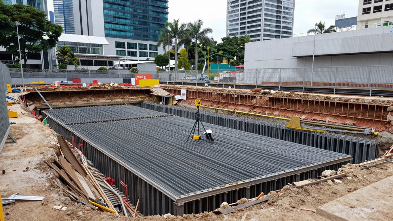
Construct the ground model by correlating investigation results, geological interpretation, laboratory testing, and observed groundwater conditions. Identify fill, soft marine or estuarine deposits, residual soils, weathered rock, and any reclaimed ground, while recording the uncertainty at layer boundaries. Characteristic values for unit weight, effective strength, undrained strength, stiffness, permeability, and interface properties should be selected with consideration of spatial variability and the failure mechanism being checked.
Do not treat a single average soil profile as representative where weak seams or variable fill could control deformation. Drainage assumptions must distinguish total-stress and effective-stress behavior, and stiffness parameters should be compatible with the strain range used for movement predictions. The resulting model should state both the adopted values and the evidence supporting them.
Account for surcharge, traffic, construction, and imposed loads
Surcharge actions may arise from road traffic, cranes, spoil heaps, stored materials, temporary site facilities, neighboring buildings, and permanent floor or foundation loads. Their magnitude, footprint, distance from the wall, duration, and ability to move during construction should be recorded. Loads from construction equipment can be particularly important when access is close to the excavation crest.
A practical action register helps prevent omissions. It should distinguish loads that are present continuously from those that occur only during a particular excavation or propping stage. Where load distribution is uncertain, sensitivity checks can show whether the selected ERSS geometry remains adequate across realistic alternatives.
Model groundwater, seepage, drawdown, and drainage conditions
Groundwater should be based on monitoring over a period that captures seasonal and construction-related variation, supplemented by an assessment of recharge and nearby drainage. Consider perched water, artesian pressures, leaking services, tidal influence where relevant, and the possibility that pumping changes the external hydraulic regime. Hydrostatic pressure, seepage forces, internal water levels, and temporary drawdown should be assigned consistently to each stage.
The design should examine both drained and undrained responses where the soil and construction rate justify them. A drainage strategy may include relief systems, sumps, cut-off walls, waterproofing, or permanent collection systems, but each measure must be checked for clogging, maintenance, discharge restrictions, and consequences of failure. Uncontrolled drawdown can transfer risk to neighboring ground through settlement, even when the wall itself remains stable.
Include seismic, accidental, and temporary construction-stage actions where relevant
Singapore projects should confirm whether seismic action is relevant to the structure, ground profile, and authority requirements rather than assuming it is automatically absent or governing. Accidental situations may include impact, anchor loss, prop removal, local obstruction, fire exposure, or an unexpected water inflow, depending on the site and system. Temporary wind, rainfall, equipment, and construction loads should also be considered where they affect exposed elements or stability.
The construction sequence is itself a source of action. Excavation lifts, installation tolerances, prestressing, strut preloading, casting of slabs, and removal of supports can produce transient force paths that do not occur in the final condition. Aman Engineering Consultancy’s documented positioning around international standards is relevant when a project requires a consistent engineering basis across Singapore, UK, UAE, or Malaysian compliance contexts, but the project-specific load model remains decisive.
Compare DA1 vs DA3 for Eurocode 7 design
The choice between DA1 and DA3 is not a preference between two software settings. It determines how partial factors are applied and how geotechnical actions, structural actions, and soil parameters are combined for verification. The engineer should compare the approaches using the same geometry, characteristic model, and design situations, then explain why one or more combinations govern. The abbreviations should also be kept distinct from unrelated online results such as a DA1 and DA3 comparison; in this article they refer to Eurocode 7 design approaches.
Understand the purpose of design approaches and partial factors
Design approaches provide a structured way to achieve a target reliability while recognizing the different uncertainties in actions, material properties, and resistances. Partial factors may be applied to actions, soil strength or stiffness parameters, and resistances according to the adopted National Annex and the relevant verification. They are not interchangeable safety multipliers, and applying them twice or to the wrong quantity can produce a misleading result.
For an ERSS, the effect of a factor can vary with the failure mode. Factoring an unfavorable surcharge, reducing soil strength, or modifying passive resistance may shift the critical slip surface, support reaction, embedment, or wall moment. The calculation record should therefore show the factored inputs and the resulting mechanism, rather than only reporting a final utilization ratio.
Apply DA1 combination 1 and combination 2 correctly
DA1 generally requires verification using two combinations, with different treatment of actions and soil or material parameters. Combination 1 commonly tests factored actions with otherwise characteristic material parameters, while combination 2 commonly tests characteristic actions with factored material parameters, subject to the exact SS EN 1997-1 and Singapore National Annex provisions adopted for the project. Both combinations must be run and checked for every relevant limit state.
The engineer should not assume that the larger wall moment is automatically the governing result. One combination may control sliding, another bearing, and another structural resistance or global stability. Keep the combinations separate in the model and report the governing result for each mechanism.
Apply DA3 with geotechnical and structural actions
DA3 applies factors to the geotechnical actions and material parameters in the manner specified by the adopted design basis, while structural actions are treated through the relevant structural design framework. This distinction matters where building loads, traffic, temporary plant, or support reactions interact with the soil-structure system. The analysis must make clear which action is classified as geotechnical, which is structural, and where the load is transferred between the two domains.
For example, an imposed load from an adjacent foundation may enter the geotechnical model as a surcharge, while a connection or capping beam must be checked as a structural component. The interface cannot be resolved by simply applying every factor to every input. It requires a documented load path and consistency between the geotechnical and structural calculations.
Select and justify the governing design approach for permanent ERSS
Select the approach required by the Singapore National Annex and project brief, then use the alternative approach as a comparison where it helps expose sensitivity or clarify the governing mechanism. The final choice should be supported by the ground model, construction method, consequences of failure, interaction with permanent works, and the design situations considered. If DA1 combination 1 and combination 2 produce different governing mechanisms, retain both results in the design record.
A useful comparison is not a contest to find the smallest wall. It shows where the design is sensitive and whether a change in embedment, support level, drainage, or surcharge assumption changes the conclusion. A concise explanation of which mechanism governs is often more valuable to a reviewer than a long table of unexplained factors.
Size the ERSS against ultimate limit states
ULS verification must cover the full system, from the retained soil and groundwater to the wall, supports, connections, and foundation interface. A wall that satisfies bending resistance can still fail through rotation, sliding, hydraulic instability, or a deep-seated mechanism. The analysis should therefore test plausible failure surfaces and load paths rather than relying on one simplified equilibrium check.
Check rotational failure, sliding, and bearing resistance
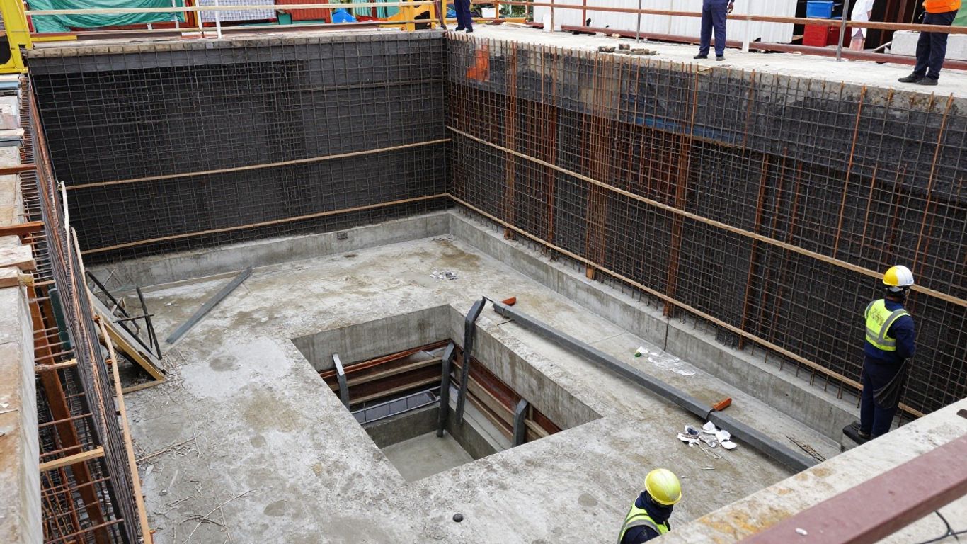
For a cantilever or supported wall, determine the earth pressure distribution, hydrostatic effects, surcharge contribution, support reactions, and passive resistance below excavation level. Embedment should be sufficient for the selected support condition and should allow for reduced passive resistance where disturbance, soft layers, groundwater, or construction tolerances make full mobilization unrealistic. Check rotation, sliding, toe stability, and bearing or interface resistance as separate mechanisms.
The calculation should distinguish between free-earth and fixed-earth assumptions where those methods are used, and it should state how wall flexibility affects pressure redistribution. Anchor or strut forces must be compatible with the wall equilibrium and with the resistance available in the ground. Local excavation geometry, corners, openings, and changes in support spacing can create effects that a two-dimensional idealization does not capture.
Assess global stability and deep-seated failure mechanisms
Global stability checks should include slip surfaces passing behind the wall, beneath the excavation, through weak strata, and around adjacent foundations where applicable. These analyses need the same design situations and groundwater assumptions used for local checks. A stable wall section does not guarantee a stable overall soil mass, particularly where a weak layer extends beyond the excavation footprint.
Consider three-dimensional effects, staged excavation, strut levels, anchor inclination, and the influence of nearby loads. Where the site includes reclaimed or variable ground, use sensitivity analyses to test the effect of weaker zones and uncertain interfaces. Results should identify the critical surface, resistance components, and margin under the adopted design approach.
Verify structural resistance of walls, struts, anchors, and connections
Structural checks should cover axial force, bending, shear, buckling, interaction effects, local instability, fatigue where relevant, and the behavior of connections. For reinforced concrete walls and capping beams, check reinforcement, crack control, anchorage, cover, construction joints, and durability. Steel walls, walers, struts, brackets, and plates require member and connection checks consistent with the applicable structural standard.
Permanent ground anchors need verified tendon resistance, bond capacity, corrosion protection, lock-off or stressing requirements, testing, and access assumptions. Struts need checks for buckling, eccentricity, preload, temperature effects, installation tolerance, and accidental loss where that situation is relevant. Aman Engineering Consultancy can provide design and back-to-back engineering endorsement, but the endorsed package must still show the actual force paths and design checks for the selected project.
Check hydraulic failure modes, including piping and uplift
Hydraulic ULS checks should consider piping, internal erosion, boiling, uplift, heave, loss of effective stress, and instability caused by excessive seepage gradients. Cut-off walls and drainage systems should be assessed together, because reducing inflow may alter external groundwater levels and settlement while increasing internal water pressures if drainage is inadequate. The analysis should cover both normal operation and credible drainage or pumping failures.
Where uplift acts on a base slab or temporary formation, verify the available resisting weight and any reliable tensile or anchorage contribution. Seepage analysis should use realistic permeability contrasts and boundary conditions, with attention to corners, joints, penetrations, and changes in ground level. Hydraulic stability is not a secondary check in a high-groundwater excavation; it can govern the entire construction method.
Complete serviceability and deformation checks
Serviceability checks translate engineering movement into consequences for people, structures, utilities, finishes, and operations. They should be carried out for the construction sequence as well as for the final permanent condition. The acceptable value is site-specific and should reflect asset sensitivity, not simply the capacity of the retaining wall.
Establish acceptable movement limits for neighboring structures and utilities
Set movement limits in consultation with the owners and designers of adjacent assets. A historic masonry building, flexible buried pipe, railway installation, and modern reinforced-concrete frame may tolerate different combinations of settlement, angular distortion, horizontal strain, vibration, and rotation. Define trigger and alarm values separately from the ultimate acceptance limit so that action can begin before damage occurs.
The assessment should include pre-existing defects and baseline surveys. Utility tolerances may be controlled by joint movement, service continuity, or leakage rather than by visible structural cracking. Where the consequences are uncertain, use conservative limits initially and refine them only with documented evidence and monitoring.
Calculate wall deflection, ground settlement, and lateral displacement
Estimate wall deflection and ground settlement using methods suitable for the wall stiffness, support sequence, soil model, groundwater regime, and excavation geometry. Simple beam-spring approaches can be useful for preliminary sizing, while numerical analyses may be needed where soil layering, staged construction, adjacent foundations, or three-dimensional effects are significant. Inputs should be calibrated against comparable local experience only with care.
Report displacement profiles, not just maximum values. The location and shape of a settlement trough can be more damaging than a larger isolated movement in an unoccupied area. Compare predicted movements with the agreed limits at each excavation stage and identify whether deformation is recoverable, progressive, or likely to continue after construction.
Evaluate anchor movement, strut loads, and connection behavior
Support movements and force changes should be checked as part of the system response. Anchors may experience stressing losses, bond movement, creep, or load redistribution as excavation proceeds; struts may attract unexpected force because of preload, temperature, alignment, or slab interaction. Connections and walers must be stiff enough to distribute reactions without local overstress or excessive distortion.
The monitoring plan should be capable of distinguishing a changing support load from an instrument error or an isolated reading. Where a connection is inaccessible after completion, its detailing and installation tolerances deserve particular attention. Temporary support reactions transferred into permanent slabs, beams, or walls must be checked for both temporary and final conditions.
Consider long-term effects such as creep, consolidation, and corrosion
Long-term performance may be affected by consolidation of compressible layers, creep of soils and anchors, shrinkage and temperature effects in concrete, and corrosion of exposed or inadequately protected steel. Groundwater chemistry, drainage maintenance, waterproofing defects, and access for inspection should be incorporated into the design life assessment. Permanent works should not rely on a temporary measure that cannot reasonably be maintained.
Where consolidation is expected, model the time-dependent change in effective stress and settlement, including the influence of drawdown or new permanent surcharge. For anchors and steel components, specify protection systems, inspection intervals, and replacement assumptions where practicable. The design record should state which long-term effects are calculated and which are controlled through detailing or monitoring.
Develop a robust permanent ERSS design
Once the governing mechanisms and movements are understood, the design can be developed around the whole construction sequence. The most efficient solution is not necessarily the lightest wall; it is the arrangement that remains buildable, inspectable, durable, and compatible with the permanent structure. Decisions should be tested against access, tolerances, drainage, and authority requirements before they are frozen in drawings.
Select wall type, embedment, and support arrangement
Choose the wall type by balancing soil and groundwater conditions, depth, stiffness, installation constraints, vibration, water control, and the intended permanent function. Secant piles can provide a water-tight interlocking wall for deep excavations up to about 30 m, while diaphragm walls are suited to very deep excavations exceeding 30 m. Sheet piles may be practical for suitable soft-soil applications, but noise, vibration, corrosion, and installation limits require careful review.
Set embedment and support levels from the governing ULS and SLS results, then review whether the construction plant can install the system to the required tolerance. Struts may preserve neighboring property rights where anchors cannot cross boundaries, while permanent anchors may provide a cleaner excavation but require easements, testing, corrosion protection, and long-term access assumptions. The selected arrangement should be explainable in both geotechnical and constructability terms.
Design permanent anchors, struts, capping beams, and facing systems
Permanent anchors should be designed for the required service life, stressing sequence, proof or suitability testing, corrosion protection, bond-zone separation, and failure consequences. Strut systems need clear load paths through walers, brackets, capping beams, slabs, and foundations, with allowance for construction tolerances and removal or transfer stages. Capping beams should be checked for wall alignment, diaphragm action, reinforcement continuity, and connection to the permanent structure.
Facing and architectural interfaces should address water ingress, fire exposure where applicable, cracking, joint treatment, access, and future inspection. Where the ERSS becomes a basement wall, the interface between retaining wall, base slab, intermediate slabs, waterproofing, and internal finishes should be drawn as a coordinated detail rather than left to site resolution.
Provide drainage, waterproofing, corrosion protection, and durability measures
Durability begins with a realistic exposure and maintenance strategy. Specify concrete cover, concrete quality, joint waterstops, protective coatings, sacrificial thickness where appropriate, anchor protection, drainage layers, pumps, sumps, and discharge arrangements according to the actual environment. The system should remain safe if a drain becomes partially blocked or a pump is temporarily unavailable.
Waterproofing details need continuity at corners, construction joints, penetrations, pile interfaces, and slab connections. Corrosion protection should address the permanent exposure, not only the installation period. Materials and details that cannot be inspected after backfilling should have a clear quality-control and acceptance procedure before they are concealed.
Coordinate ERSS geometry with foundations, basements, utilities, and site access
Coordinate the wall line and support zones with pile caps, footings, basement columns, ramps, stairs, plant rooms, drainage runs, utility corridors, and waterproofing zones. Conflicts often arise when a wall is moved for architectural reasons after anchors, capping beams, or excavation stages have already been designed. Maintain a single coordinated geometry and identify no-go zones for drilling, excavation, and temporary support.
The construction sequence should show how equipment enters, how spoil is removed, how supports are installed and preloaded, and how loads transfer into the completed basement. Aman Engineering Consultancy’s global and regional engineering positioning can support projects that need design coordination across international standards, but local site constraints, authority conditions, and the selected Singapore National Annex remain the controlling basis for this ERSS.
Document, review, and implement the Eurocode 7 design
A technically sound ERSS can still fail in practice if assumptions are hidden or the construction sequence is vague. The design package should allow a reviewer, contractor, site engineer, and monitoring team to understand what was assumed, what must be verified, and what response is required when conditions differ. Documentation is therefore part of the engineering control system, not an administrative afterthought.
Present assumptions, design parameters, load combinations, and partial factors
Begin the report with the design brief, site model, geometry, design life, consequence classification, groundwater assumptions, construction sequence, and applicable standards. Tabulate characteristic soil parameters, interface assumptions, surcharges, water levels, support properties, material strengths, and tolerances. State every partial factor and identify whether it applies to an action, material parameter, resistance, or structural component.
The report should distinguish measured information from adopted assumptions and should record unresolved uncertainties. Include sketches of pressure diagrams, load paths, support reactions, and stage geometry where they make the calculation easier to audit. A clear basis of design reduces the risk that a later reviewer mistakes a temporary assumption for a permanent requirement.
Show calculation outputs for DA1, DA3, and governing limit states
Present the results in a way that connects numerical output to a physical failure mechanism. For DA1, show combination 1 and combination 2 separately; for DA3, identify the treatment of geotechnical and structural actions. Report utilization, resistance, displacement, critical slip surface, wall moment, shear, axial force, support reaction, embedment demand, and hydraulic gradients where relevant.
The comparison should explain why a result governs and what design change would address it. A compact summary table can help reviewers see the relationship between the check, governing approach, and response, provided the detailed calculations remain available behind it.
| Verification area | Typical governing output | Design response |
|---|---|---|
| Wall equilibrium | Rotation, sliding, or embedment demand | Revise embedment, support level, or pressure model |
| Global stability | Critical slip surface and utilization | Improve geometry, staging, or ground treatment |
| Structural resistance | Moment, shear, axial force, or buckling | Increase section, reinforcement, or connection capacity |
| Hydraulic stability | Gradient, uplift, heave, or piping risk | Improve cut-off, drainage, pumping, or slab resistance |
The table is a reporting aid, not a substitute for the underlying analysis. Each output should be traceable to a design situation, a set of factors, and a stated acceptance criterion before the package is issued.
Define instrumentation, monitoring thresholds, and observational-method responses
Monitoring should measure the behaviors that matter: wall movement, ground settlement, adjacent-structure response, support loads, groundwater levels, piezometric pressure, and selected utility movements. Establish baseline readings before excavation and define alert, action, and stop-work thresholds with named responsibilities. The observational method is effective only when the response to a threshold exceedance is designed in advance.
A practical response plan should cover the following sequence:
- Check the reading, instrument condition, and recent survey control.
- Compare the trend with excavation stage, rainfall, pumping, and support installation.
- Notify the responsible engineer and affected stakeholders at the defined threshold.
- Implement a pre-designed control measure, such as slowing excavation, adding support, reducing pumping, or improving drainage.
- Record the decision, outcome, and any required design revision.
This sequence turns monitoring into an active design control rather than a collection of readings. It also gives the contractor and reviewing engineer a common basis for acting before movement becomes irreversible.
Coordinate drawings, specifications, construction sequence, and independent checks
Drawings should show wall geometry, reinforcement or steel sections, embedment, support levels, anchor zones, drainage, waterproofing, joints, tolerances, instrumentation, and interfaces with permanent works. Specifications should define materials, testing, installation methods, stressing, inspection, hold points, acceptance criteria, and remedial procedures. The sequence must match the analysis stages, including excavation lifts, support installation, preload, slab casting, and support transfer.
Independent checking should cover the design basis, ground model, DA1 and DA3 application, ULS and SLS results, structural detailing, hydraulic assumptions, and construction methodology. Aman Engineering Consultancy provides professional engineering consultancy and endorsement services, so its involvement should be tied to a clearly defined review scope, submission responsibility, and document-control process. The final issue should make clear which drawings and calculations are approved for construction and how revisions are managed.
Conclusion
Sizing a permanent ERSS under SS EN 1997-1 in Singapore is a coordinated process of ground interpretation, action definition, DA1 and DA3 verification, structural and hydraulic checking, movement control, and construction planning. The strongest designs make their assumptions visible, test the real failure mechanisms, and connect every calculation to a buildable detail and a monitoring response. That discipline gives the permanent retaining system a defensible basis from investigation through completion.
Frequently Asked Questions
What is the difference between DA1 and DA3?
DA1 uses two combinations that distribute partial factors between actions and material parameters, while DA3 applies factors according to the adopted treatment of geotechnical and structural actions. The exact factors must be taken from SS EN 1997-1 and the Singapore National Annex used for the project.
Should both DA1 combinations be checked?
Yes. DA1 combination 1 and combination 2 can govern different mechanisms, such as wall bending, sliding, bearing, or global stability. They should be modelled and reported separately rather than replaced by whichever produces the larger single force.
What information is needed before sizing an ERSS?
The design needs excavation geometry, retained and founding levels, soil layering, characteristic strength and stiffness parameters, groundwater conditions, surcharges, adjacent assets, construction sequence, support arrangement, and performance requirements. The quality of the ground model is particularly important.
Which failure modes should a permanent ERSS design cover?
The design should address rotational failure, sliding, bearing or toe resistance, global and deep-seated instability, structural resistance, buckling, connection failure, piping, uplift, heave, and excessive deformation. The relevant modes depend on the site and system.
How are movement limits selected?
Movement limits are selected from the sensitivity and function of neighboring buildings, utilities, roads, rail assets, and finishes. Baseline surveys, asset-owner requirements, predicted deformation, and consequence of damage should all inform the limits and monitoring thresholds.
Do groundwater conditions affect the design approach?
Groundwater affects earth pressures, effective stress, seepage forces, uplift, piping, heave, wall waterproofing, and the risk of drawdown-induced settlement. It should be modelled for normal, construction-stage, and credible drainage or pumping failure conditions.
What should the final design report contain?
It should contain the design basis, investigation interpretation, parameters, geometry, actions, design situations, DA1 and DA3 combinations, partial factors, ULS and SLS results, structural checks, hydraulic checks, drawings, specifications, construction sequence, monitoring thresholds, and independent review records.