
Introduction to Deep Excavation
Connection detailing between permanent earth retaining stabilising structures (ERSS) walls and basement floor slabs governs the structural integrity, waterproofing performance, and long-term serviceability of deep basement construction. Permanent ERSS walls can double as permanent basement retaining walls, making the interface between these walls and floor slabs one of the most structurally demanding and leak-prone zones in any underground project. Getting the detailing right at this junction-where lateral earth pressures, hydrostatic forces, and differential movement all converge-determines whether a basement performs as designed or develops costly defects within years of completion.
This guide covers structural load transfer mechanisms (shear keys, starter bars, rebar couplers), reinforcement continuity requirements, waterproofing system integration, and construction sequencing considerations specific to Singapore’s regulatory frameworks under the Building and Construction Authority (BCA), with relevant context from structural engineering, geotechnical engineering, and soil mechanics. The target audience includes structural engineers, geotechnical engineering professionals, contractors, engineering firms, and project managers working on deep excavation and tunneling projects involving permanent ERSS walls.
In direct terms: connection detailing involves designing reinforcement continuity, shear transfer mechanisms, and integrated waterproofing systems at wall-slab interfaces to ensure structural stability and water resistance under sustained lateral earth pressures and hydrostatic water pressure, with the exact approach depending on the project design model used for structural and geotechnical coordination. Detailing the connection between permanent ERSS walls and basement floor slabs requires careful coordination across structural, geotechnical, and waterproofing disciplines.
By the end of this guide, you will understand:
-
How lateral earth pressures and hydrostatic forces are transferred through the wall-slab interface via shear keys, dowel bars, and reinforcement systems
-
Specific reinforcement detailing requirements including lap lengths, anchorage, and coupler specifications per Singapore Standards
-
Waterproofing integration strategies using waterstops, membranes, and crystalline admixtures at construction joints
-
Construction sequencing impacts on connection quality for both top down and bottom-up methods
-
BCA regulatory compliance requirements for ERSS submissions and structural inspections
Understanding ERSS Wall-Slab Interface Fundamentals for Sheet Pile Walls
Permanent ERSS walls-including diaphragm walls, secant piles, sheet pile walls, and contiguous bored piles-serve dual roles in deep basement projects. During construction, they retain the surrounding soil mass and control ground movement. In the permanent condition, they function as the basement’s perimeter retaining wall. These systems are often extremely stiff and rely on slab restraint as permanent works take over. ERSS includes sheet piles, secant piles, and diaphragm walls, each suited to different excavation depths, soil conditions, and water tightness requirements. The basement floor slab typically acts as a horizontal diaphragm that restrains the retention wall, replacing temporary supports such as steel struts or ground anchors as excavation proceeds and permanent structures take shape.
ERSS must resist lateral earth pressures and hydrostatic forces throughout its service life. During the construction phase alone, ERSS must endure severe loading conditions for 12 to 24 months-temporary ERSS typically lasts 12 to 24 months during construction before permanent elements take over, with wall behavior and pressure redistribution during deep excavation also influenced by the arching effect. The interface between the wall and slab must therefore be designed to transmit these forces reliably across the full design life.
Load Transfer Mechanisms
Lateral earth pressure transfer from ERSS walls to basement slabs occurs through a combination of shear keys, reinforcement connections, and friction at the construction joint. Dowel bars extend from the ERSS wall into the concrete floor slab to transfer horizontal shear forces, while shear keys may be required where significant horizontal shear must be transferred. Vertical load distribution and moment transfer at wall-slab junctions depend on reinforcement continuity and the stiffness compatibility between the wall and slab elements. Soil-structure interaction influences wall stiffness and deflection, which in turn affects the magnitude and distribution of forces at the interface.
Proper load transfer prevents differential settlement and structural failure. Differential settlement characteristics may vary between permanent shoring elements and interior foundations, meaning the connection must accommodate relative movements while maintaining clear load paths. Construction-stage loading must be accounted for in slab-wall connection designs, as the interface may experience higher temporary loads during construction than in the permanent condition.
Interface Design Principles
Structural continuity at the wall-slab interface demands that reinforcement detailing, concrete placement, and joint preparation work together as an integrated system. The reinforcement cage within the ERSS wall must align with starter bars or couplers that connect into the slab reinforcement. Concrete cover requirements-minimum 40 mm when cast against prepared ground per SS 544-must be maintained even in congested zones.
Waterproofing integration is inseparable from structural detailing. The slab-wall interface is one of the most common leakage locations in construction, and any waterstop, membrane, or sealant system must be coordinated with the reinforcement layout to avoid conflicts. Holistic coordination of structural, geotechnical, and waterproofing design is crucial for interface stability.
These principles apply regardless of construction sequence, but the specific detailing approach varies substantially depending on whether the project utilizes a top down or bottom-up method-a distinction explored in the sections that follow.
Connection Detailing Requirements and Applications
Building on the load transfer principles above, the specific detailing at wall-slab connections involves three interdependent systems: reinforcement continuity, shear transfer, and waterproofing. Each must be designed, specified, and inspected with precision.
Reinforcement Continuity Systems
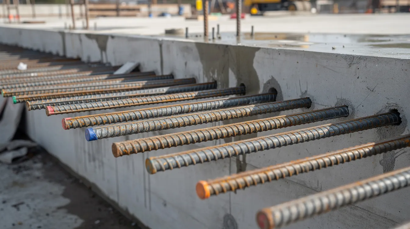
Starter bars are vertical or horizontal reinforcement bars projecting from the ERSS wall into the slab. For diaphragm wall construction, these bars are typically cast into the wall panel and left projecting for later connection. Embedment length must satisfy anchorage requirements per SS EN 1992-1-1: for Grade B600 rebar with bar diameters exceeding 16 mm, anchorage length may reach 37×Ø in good bond conditions, while lap lengths for tension bars in C32/40 concrete range from approximately 47×Ø for Ø10–16 mm bars to 52×Ø for larger diameters. Reinforcement spacing near the wall-slab interface shall not exceed 200 mm, with clear spacing not less than 100 mm (75 mm in lap zones), per LTA EGD 09/106 standards.
Rebar couplers are mechanical connectors used to splice reinforcement where lap overlaps are impractical-common in top down construction or where the reinforcement cage geometry prevents adequate overlap. Couplers must match the rebar grade (often B600H per Design Guide BC5:2019) and be verified for moment and shear demands. They reduce congestion compared to traditional laps but require strict alignment tolerances and post-installation inspection.
Lap splices remain the most common connection method for conventional reinforcement connections. Poor bond conditions or congested reinforcement require longer lap lengths. Bundled bars are generally prohibited at the interface zone due to bond and cover concerns.
Shear Key Design and Installation
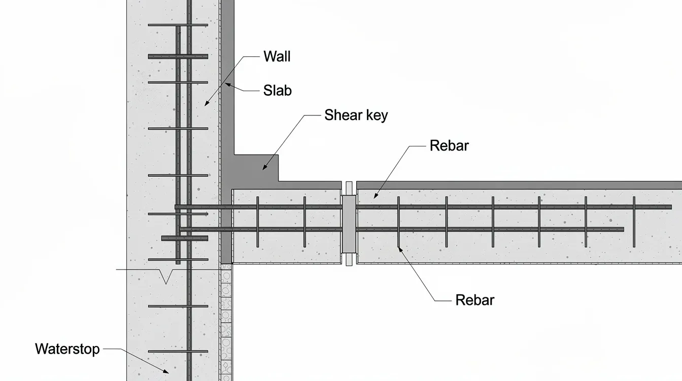
Shear keys are physical projections or recesses cast into the wall base that mechanically interlock with the slab concrete. Their geometry-height, width, spacing-is sized based on the lateral forces to be transferred. Research published in MDPI’s Buildings journal on the flexural performance of underground combined walls confirms that specimens with interface roughening and shear grooves demonstrated no interfacial slip under load, with significantly higher ductility and load-bearing capacity compared to smooth interfaces.
Construction joint preparation is equally critical. The surface must be clean, free of laitance, and roughened to a minimum 3–5 mm profile. Studies using laser scanning to quantify diaphragm wall surface roughness show that “very rough” surfaces produce interface friction angles (δ) of 23°–32°, with resultant effects on earth pressure coefficients that can vary by 5–10% compared to smooth surfaces. Open retaining systems can also be vulnerable to ground loss if fines migrate through gaps or poorly controlled interfaces during excavation. Form oil, surface bleeding, or inadequate roughening can negate the shear key’s benefit entirely.
Integration with waterproofing systems at shear key locations requires careful sequencing: waterstops must wrap around the key geometry, and membranes must accommodate the profile change without tearing or delamination while helping prevent movement of adjacent soil and wall elements as the slab connection is completed.
Waterproofing Detail Integration
Waterstops must be installed at the cold joint between the floor slab and the retention wall-this is non-negotiable under both BS 8102:2009 (Type A barrier, Type B integral, and Type C drained classifications) and SS 637:2018. Continuous PVC waterbars (centrally placed, ribbed) or hydrophilic swellable strips are positioned along the construction joint. Swellable waterstop products can achieve volume increases of up to approximately 300% and resist hydrostatic head up to 100 m (~10 bar) when fully submerged, providing robust sealing against joint movements.
Membrane systems-whether external positive-side HDPE pre-applied membranes or negative-side interior systems-must wrap continuously across the wall-slab junction with properly sealed overlaps. Penetrations from starter bars, couplers, tie-backs, and MEP services create discontinuities that require sleeved and collared sealing details. Integral waterproofing admixtures (crystalline types) added to the concrete mix reduce permeability and contribute to Type B systems per BS 8102, though they do not replace physical waterstops at construction joints.
Key detailing points at the interface:
-
Waterstop profile must be continuous and unbroken around the full perimeter
-
Membrane overlaps at the junction require minimum 150 mm sealed laps
-
All penetrations need flexible collars compatible with the membrane chemistry
-
Differential movement should be accommodated in the slab-wall connection to prevent structural issues at waterproofing terminations
The complexity of integrating all three systems-reinforcement, shear transfer, and waterproofing-within the same narrow zone is why 3D BIM modeling and clash detection are increasingly essential during the design phase.
Design Process and Construction Implementation
With detailing requirements established, the practical implementation involves systematic design calculations, construction method selection, and rigorous quality control-all within Singapore’s regulatory frameworks.
Design Calculation Procedure
Detailed calculations are required for every permanent ERSS wall-slab connection. Eurocode 7 applies partial factors to loads and soil properties, providing the basis for geotechnical force computation. The following table outlines the sequential design process:
-
Determine lateral earth pressures acting on the ERSS wall from the geotechnical analysis-including active, at rest, and passive conditions, hydrostatic side pressure, surcharges, and groundwater drawdown effects. The Clough and O’Rourke method estimates lateral wall deflection for initial assessments, while 3D FEM modeling captures soil-structure interaction benefits for complex geometries. Note that for rough wall-base interfaces, the induced δ angle increases passive earth pressure coefficients.
-
Calculate required shear transfer capacity at the wall-slab interface based on applied loads. From lateral load analysis, compute shear forces at the wall base that must be transferred into the slab via shear keys and reinforcement. Size shear keys (depth, width, spacing) so that concrete shear capacity exceeds design shear, accounting for interface roughness and sliding friction.
-
Size reinforcement and connection elements to resist calculated bending moments and shear forces with appropriate safety factors. Select bar sizes (typically Ø16–Ø32 mm for main flexural bars at wall-slab interfaces), compute lap or anchorage lengths per SS EN 1992, and specify couplers where laps are impractical. Include safety factors for bond, cover, and concrete strength. The structural modelling and analysis process must verify deformation compatibility between wall and slab, including shrinkage and thermal loads.
-
Verify structural adequacy using finite element and numerical analysis for irregular geometries, asymmetrical excavation, or high loads. Numerical modeling should check crack width control per SS EN 1992 at the wall-slab junction, confirm that the serviceability limit state is satisfied, and remain consistent with the project design model and instrumentation feedback. Advanced instrumentation provides real-time monitoring of displacements during construction to validate design assumptions.
-
Design the waterproofing system: select membrane type, waterstop profile, and sealing details. Verify that waterstop products are rated for the expected hydrostatic head. Detail termination points, overlaps, and penetration seals. Check compliance with BS 8102 and SS 637. Material and system selection may also be reviewed for project carbon footprint where the design brief includes sustainability targets.
Construction Method Comparison
The choice between top down and bottom-up construction fundamentally affects connection detailing, quality control feasibility, and construction sequence coordination.
|
Factor |
Top-Down Construction |
Bottom-Up Construction |
|---|---|---|
|
Starter bar installation |
Bars cast into diaphragm walls during initial wall construction; slab cast against exposed bars; alignment critical |
Bars projecting from wall base; slab cast in sequence from lowest level upward; easier access for inspection |
|
Rebar coupler usage |
Frequently required due to restricted access below completed slabs; allows connection without lap space |
Less common; standard laps often feasible with adequate formwork clearance |
|
Shear key formation |
Formed during d wall panel casting; geometry must be precise as access for correction is limited |
Can be formed at construction joint with conventional formwork; easier to inspect and rectify |
|
Waterproofing continuity |
Challenging-membranes must be pre-applied or installed in confined spaces; waterstop placement requires advance planning |
More straightforward-waterstops placed on exposed joint surfaces before slab pour |
|
Construction speed |
Faster overall program-basement and superstructure proceed simultaneously |
Slower-each level completed before proceeding upward |
|
Quality control |
More difficult due to limited access; requires experienced crews and rigorous inspection protocols |
Easier inspection access; greater opportunity for correction before next pour |
|
Cost implications |
Higher unit cost for connections due to coupler requirements and access constraints; offset by program savings |
Lower connection costs; higher overall program duration |
The synthesis for method selection depends on project-specific constraints. For very deep excavation in challenging soil conditions-particularly in Singapore’s marine clay and soft clay deposits-top down construction often provides better ground settlement control and allows the basement floor slab to serve as a strut during excavation, preventing movement of the surrounding soil mass. Shallow stabilization alternatives such as soil nailing may suit different site conditions, but they do not replace the wall-slab detailing demands of permanent deep-basement ERSS. Local geology also shifts method selection and movement-control expectations; over-consolidated formations such as London Clay in other markets behave differently from Singapore soils. However, bottom-up methods offer superior quality control at connections, allowing engineers to inspect every starter bar, waterstop, and joint surface before concrete placement. BCA mandates a zero-tolerance approach to excavation failure, making the quality control advantages of bottom-up methods particularly relevant for higher-risk geotechnical works where Independent Checkers are required.
Common Challenges and Solutions
Field implementation of wall-slab connections consistently encounters three categories of problems. Recognizing and addressing these during design-rather than during construction-prevents costly remediation.
Reinforcement Congestion at Wall-Slab Junction
At wall-slab junctions with multiple layers of starter bars, couplers, waterstop elements, and slab reinforcement, congestion can impede concrete compaction, cause honeycombing, and reduce effective cover.
Solution: Optimize reinforcement layout using Tekla 3D steel and concrete detailing and coordinate with MEP systems before construction through comprehensive BIM modeling. Predetermine bar bending schedules, adjust rebar diameters (using fewer larger bars rather than many smaller ones where structurally equivalent), and consider couplers to eliminate lap zones. Produce mockup panels at the wall-slab interface to test concrete consolidation in congested mesh before full-scale construction. Minimum concrete cover requirements per SS 544 must be maintained even in the most congested zones-typically set at 40 mm nominal for below-grade elements cast against prepared ground.
Construction Joint Water Infiltration
Singapore’s high water table and hydrostatic conditions make the construction joint at the wall-slab interface a primary leakage path. Incomplete waterstop installation, membrane damage during reinforcement placement, or poor joint preparation can all create water ingress pathways.
Solution: Implement a multi-layer waterproofing system combining continuous PVC or hydrophilic waterstops with membrane wrap-arounds and integral crystalline admixtures. Surface roughening to 3–5 mm profile is mandatory before the slab pour, with complete removal of laitance and application of bonding agent where specified. Monitoring plans must include piezometers for water pressure measurement around the excavation to verify that hydrostatic conditions match design assumptions. Where soft clay and high water pressures coincide, basal heave is a key excavation risk that must also be checked. On some deep excavations, base improvement measures such as jet grouting may be required to control uplift and indirectly support waterproofing integrity. For the Watertown & Waterway Point project in Singapore, a hybrid ERSS approach using diaphragm walls and secant pile walls demonstrated how careful integration of waterproofing systems at wall-slab interfaces performs under challenging conditions with excavation exceeding 20 m depth and unbalanced terrain. The project utilized cross diaphragm walls that also functioned as shear walls, illustrating the structural and retaining roles that overlap at these critical junctions.
Inadequate Shear Transfer Capacity and Basal Heave
Insufficient shear key dimensions, poor surface roughening, or misaligned reinforcement can result in inadequate shear transfer at the interface-potentially leading to wall movement relative to the slab under lateral loading.
Solution: During design, size shear keys conservatively based on worst-case earth pressure analysis and verify using numerical modeling. During construction, inspect surface roughness using profile gauges and reject surfaces that do not meet the specified 3–5 mm minimum. If post-construction assessment by a structural engineer inspection reveals deficiencies, strengthening options include epoxy-bonded steel plates, carbon fiber reinforcement, or supplementary dowel installation-though these are significantly more expensive and disruptive than getting the initial detailing right.
Inclinometers measure wall deflection during excavation, and the AAA system monitors wall deflection and water pressure in real-time. BCA mandates a three-level trigger system for monitoring, using automated total stations that provide real-time monitoring of displacements. Real-time data analytics enhance geotechnical monitoring effectiveness, allowing engineers and contractors to detect problems at the interface before they become critical. These monitoring systems, combined with digital twins technology, represent the current gold standard for ground deformation tracking on deep basement projects across global metropolises.
Conclusion and Next Steps
Proper connection detailing at the interface between permanent ERSS walls and basement floor slabs is the single most critical factor in determining whether a deep basement achieves its design life without structural distress or water infiltration. The integration of reinforcement continuity (starter bars, lap splices, and couplers), shear transfer mechanisms (shear keys and roughened interfaces), and continuous waterproofing systems (waterstops, membranes, and crystalline admixtures) must be coordinated as a unified system-not as three separate disciplines working in isolation.
In Singapore, regulatory bodies including BCA regulate excavation deeper than 6 meters, and ERSS submissions require endorsement by a Professional Engineer (Geotechnical). The BCA requires a Professional Engineer’s endorsement for ERSS submissions, with typical fees for ERSS submissions ranging from S$3,000 to S$15,000. Within this framework, the qualified person oversees design submission coordination and site compliance checks. BCA mandates a two-set-of-eyes principle for geotechnical works, and Independent Checkers are required for higher-risk geotechnical works in Singapore. Understanding these regulatory requirements early in the design process prevents submission delays and costly redesigns.
Immediate next steps for your project:
-
Conduct detailed geotechnical and structural analysis of the wall-slab interface forces, including soil parameters, hydrostatic conditions, and construction-stage loading
-
Prepare connection detailing drawings showing starter bar positions, coupler locations, shear key geometry, waterstop alignment, and membrane terminations-coordinated through 3D BIM
-
Coordinate with a waterproofing consultant to specify waterstop products and membrane systems rated for site-specific hydrostatic conditions
-
Develop a monitoring plan incorporating inclinometers, piezometers, and automated total stations for real-time verification during construction
Related topics worth exploring include basement wall design optimization for other retaining systems, advanced waterproofing systems for structures in flowing sands and marine clay conditions, and BCA structural submission requirements for deep basement projects. For projects involving soldier piles with timber or concrete lagging, contiguous bored piles that have small gaps between them, or sheet piles typically used for shallower excavations, the interface detailing principles remain consistent but the specific connection methods vary based on the structural capacity of each wall type.
Additional Resources and Case Studies
-
BCA Guidelines for ST Plan Applications: Covers ERSS submission requirements for excavations deeper than 6 m, including geotechnical analysis, performance monitoring, and construction sequencing requirements. Diaphragm walls are used for very deep excavations and MRT works, while secant pile walls interlock to provide water tightness for moderate-depth basements. More details are available through BCA’s structural plan submission guidelines.
-
Singapore Standards: SS EN 1992-1-1 for reinforcement detailing (anchorage, lap lengths, cover), SS 637:2018 for below-grade waterproofing, and Design Guide BC5:2019 for Grade B600 reinforcement properties and coupler specifications.
-
AMAN Engineering Consultancy: Provides temporary works design for ERSS, PE endorsement for civil and structural works, and accredited checker services for deep basement projects requiring connection detailing, structural inspections, BIM modeling, and construction authority submissions. For projects requiring investigation of existing connection defects, the firm’s building defect investigation services provide diagnostic assessment and remediation recommendations.