
Introduction
The top down construction method design and submission for permanent ERSS basements involves casting permanent basement slabs progressively from ground level downward, with each slab acting as lateral bracing for the perimeter retaining wall. In a permanent ERSS basement, the retaining wall and basement slabs are designed as one integrated system to resist earth and water pressures during excavation and throughout the building’s service life.
This article is written for structural engineers, geotechnical engineers, developers, and contractors planning deep excavation works in Singapore that require BCA approval for permanent ERSS basement construction. It focuses on the parts of the design and submission process that control approval, buildability, and performance: soil-structure interaction during staged excavation, king post vertical capacity, temporary-to-permanent load transfer, diaphragm wall to slab connection detailing, and the authority submission requirements under Singapore’s Building and Construction Authority (BCA) framework.
For urban basement projects, this method matters because permanent slabs replace much of the temporary strutting by acting as horizontal props, which helps control wall deflection and ground movement while allowing superstructure and substructure works to proceed in parallel. Perimeter retaining walls must be installed before excavation, and each newly cast basement slab then braces the excavation while transferring lateral soil pressures into the retaining wall system.
After reading this article, you will understand:
-
How soil-structure interaction governs wall deflection and ground settlement at each excavation stage
-
King post design for vertical load capacity, local buckling failure prevention, and connection to permanent columns
-
Load transfer sequencing from temporary works to the permanent structure
-
Diaphragm wall to slab connection detailing, including starter bars and waterproofing
-
BCA submission documentation requirements for deep basement excavation with permanent ERSS
Understanding Top-Down Construction for Permanent ERSS Basements
Top-down construction has the basement and support elements constructed sequentially from ground level downward: the first floor slab is cast at grade, excavation proceeds beneath it to the next level, and the same procedure repeats slab by slab until the foundation slab is reached at the desired depth. Each completed slab provides continuous lateral restraint to the embedded retaining wall design, replacing extensive temporary shoring systems that would otherwise occupy the excavation zone.
This approach suits deep urban basements where site constraints prevent installation of large temporary propping arrays, or where adjacent structures require that ERSS must limit ground deformation to protect adjacent structures. Top-down construction minimizes soil movement during excavation because permanent slabs are stiffer than temporary props and are installed earlier in the construction sequence. The top down method is especially suitable for tall buildings with deep basements where excavation control and build sequence integration are critical.
Permanent vs Temporary Support Systems
Temporary support systems use steel struts, walers, and rakers spanning between retaining walls or bearing on king posts. These elements must be designed for the full lateral earth pressure at each excavation stage, then removed once permanent slabs are in place. The bottom up method follows this pattern: excavate to full depth, cast the foundation slab, and build upward.
Permanent slab-based support differs in three specific ways. First, load paths are shorter; lateral earth pressure transfers directly from the diaphragm wall through the slab connection into the opposite wall or internal columns, without intermediate temporary members. Second, the permanent slabs carry both temporary construction loads and long-term service loads, meaning they must be designed for the envelope of both conditions. Third, permanent slabs minimize neighboring ground settlement and reduce damage risk to adjacent structures because they provide stiffer lateral bracing than temporary struts.
The role of permanent elements in excavation support requires careful design for temporary load cases. A slab designed only for permanent service loads may be undersized for the asymmetric earth pressures it experiences during staged excavation, when soil has been removed on one side but not the other.
Integration with ERSS Design
Diaphragm walls are preferred for deep, water-bearing urban excavations because they can be constructed before bulk excavation begins, forming a continuous perimeter wall with water-cutoff capability. Secant piles and tangent pile walls serve a similar function in different ground conditions, but diaphragm wall construction remains the standard choice for deep basements exceeding 15 m in Singapore’s marine clay and Old Alluvium formations. In some top-down retaining or pre-founding column arrangements, bored piles may also be used as structural elements depending on ground conditions and the project layout.
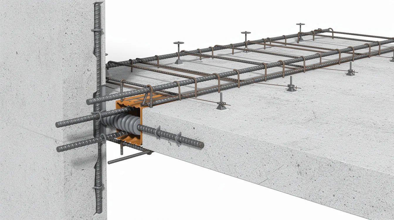
Structural continuity between the retaining wall and basement slabs depends on embedded connections. Starter bars projecting from the diaphragm wall into the slab zone must be cast into the wall panels during their construction. The reinforcement cage in each d wall panel includes these projecting bars at each planned slab level. Complex junctions must be detailed in design plans where permanent slabs meet retaining walls, accounting for differential movement, concrete shrinkage, and thermal loads at the interface.
The BCA/ACES circular distinguishes between “independent ERSS,” where the permanent structure resists in-situ earth loads without reliance on temporary works, and “dependent ERSS,” where permanent basement slabs carry loads from temporary members during construction. In the dependent case, permanent slabs require design for both temporary stage loads and final permanent loads. This classification determines the scope of QP appointments and submission requirements.
Because the retaining wall, slabs, and soil form a coupled system, both design and construction cannot treat any element in isolation. The next section explains how soil-structure interaction governs the behavior of this system across each excavation stage.
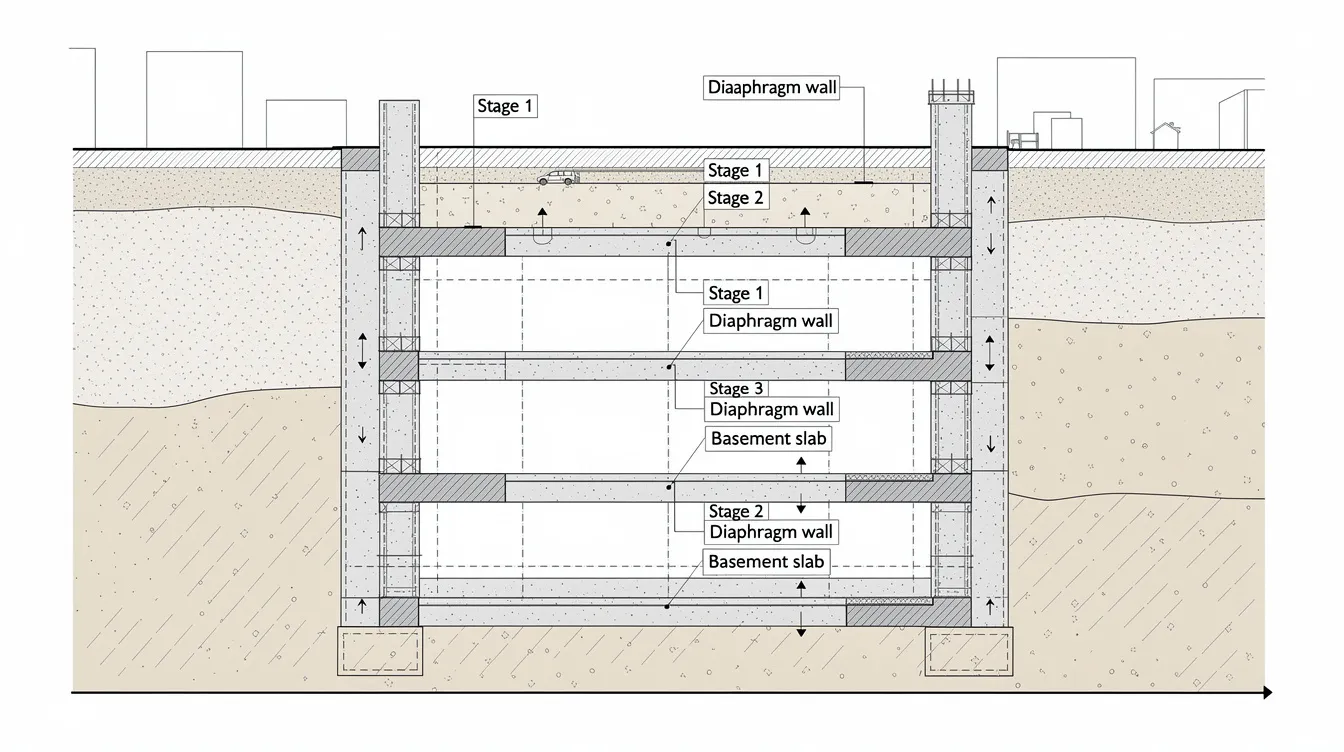
Design Considerations and Soil-Structure Interaction
The interaction between the soil mass, the retaining wall, and the basement slabs changes at every excavation stage. Removing soil below a completed slab redistributes lateral earth pressure, alters the bending moment profile in the wall, and induces ground movement behind the wall. Capturing these effects requires stage-by-stage numerical analysis.
Stage-by-Stage Excavation Analysis
Finite element modeling of the top down construction sequence applies soil mechanics to interpret changing earth pressures as each construction stage is simulated as a discrete analysis step. A typical sequence for a three-level basement includes: diaphragm wall installation, ground level slab construction, excavation to B1 level (5-6 m below ground level), B1 slab casting, excavation to B2 level, B2 slab casting, excavation to B3 level, and foundation slab construction.
At each stage, the soil stress path changes. When excavation proceeds below a completed slab, the unloaded side of the wall experiences reduced passive resistance while active earth pressure on the retained side remains. A slab-braced permanent ERSS can behave as an extremely stiff system, so expected wall movement differs from freer cantilever response. Wall deflection accumulates across stages; a wall that deflects 15 mm at Stage 3 may reach 35 mm by Stage 5 if soil stiffness is overestimated.
For Singapore’s Newton MRT station, finite element analysis of a 25 m deep diaphragm wall through marine clay into decomposed granite demonstrated that early slab installation reduced wall bending moments compared to temporary strutting. Non-linear hyperbolic soil models (Hardening Soil or HS-Small models) captured the stress-dependent stiffness of the soft clay and showed that wall movement concentrated in the marine clay layer between completed slabs. In geotechnical engineering, instrumentation and monitoring are used to validate numerical assumptions and manage uncertainty during staged excavation.
Soil parameters used in the model must match site investigation results. BCA expects the soil modulus and undrained shear strength values to correspond to laboratory and in-situ test data from the SI report. Groundwater management is critical during each construction stage to uphold stability; hydrostatic pressures behind the wall and uplift pressures beneath the excavation base must be modeled at each stage. Similar issues are seen in London Clay, where stiff over-consolidated material can still produce long-term heave and movement that require close monitoring on deep excavation projects.
Ground deformation prediction uses both numerical output and empirical methods. Instrumentation and monitoring plans must outline intervention levels for ground settlement and building tilt at adjacent structures. For excavation and tunneling projects near MRT tunnels, the Land Transport Authority imposes additional settlement limits, typically 15 mm maximum.
King Post Vertical Capacity Requirements
Plunge columns (also called king posts) are pre-installed before excavation to carry gravity loads from upper slabs before permanent columns are constructed. These steel columns are typically H-sections or fabricated box sections driven or bored into the ground, with their bases socketed into founding piles.
Vertical load on a king post includes:
-
Dead load of all completed slabs above (self-weight of concrete, typically 5-7 kN/m² per 200-250 mm slab)
-
Construction live loads (equipment, fresh concrete placement, material storage: 5-10 kN/m²)
-
Any lateral load components transferred via rakers or inclined struts bearing on the king post
Buckling governs king post capacity more often than material strength. The effective length depends on end fixity: a king post connected to a slab at its top and a pile at its base has a different slenderness ratio than one with intermediate slab connections. For a typical 12 m unsupported length with a 305×305 UC section, the slenderness ratio approaches 80-90, reducing the compression capacity to approximately 60% of the squash load. Local buckling failure of thin flanges or webs must be checked separately, with section classification per SS EN 1993.
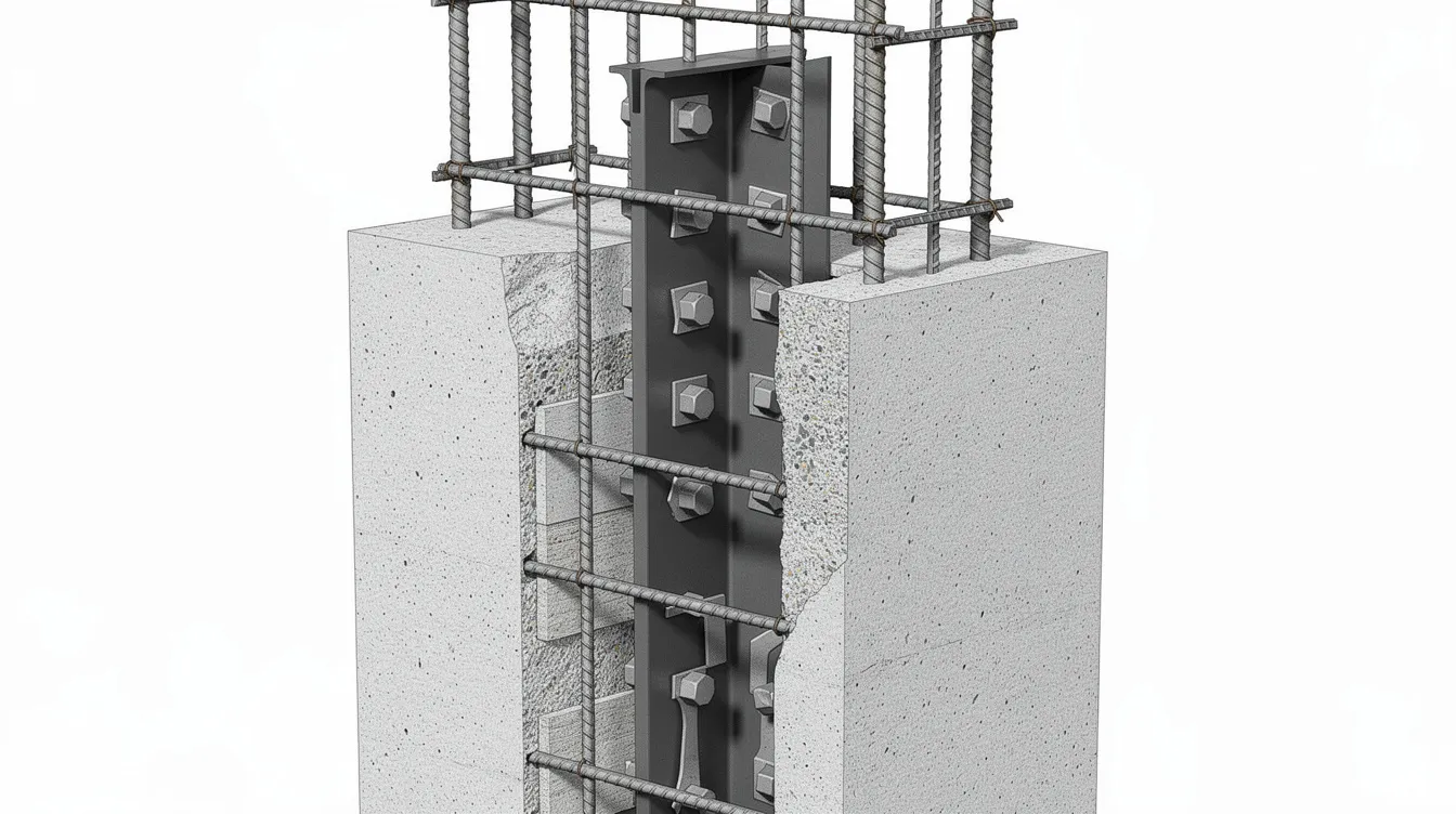
Connection between king posts and permanent columns requires precise alignment. The king post is typically encased in the permanent column concrete, with shear studs or welded plates providing composite action. Tolerances are tight: positional accuracy of ±25 mm horizontally and ±10 mm vertically is standard. Any misalignment forces load into unintended eccentricities, increasing bending demand on both the temporary and permanent elements.
Temporary to Permanent Load Transfer
The transition from temporary king posts to permanent columns is a staged process, not an instantaneous switch. When a permanent column is cast around a king post, the fresh concrete initially carries no load; the king post continues to support all vertical forces from above. As the concrete gains strength over 7-28 days, load gradually transfers through bond and shear connectors.
Strategic voids are left in slabs to facilitate excavation logistics; these openings must be infilled before the slab can carry its full design load. The construction sequence must specify when each void is closed relative to the excavation stage below.
The design must demonstrate that at no point during the transfer sequence do permanent slabs or columns experience forces exceeding their available capacity at that concrete age. This requires time-dependent analysis accounting for concrete strength gain, creep, and shrinkage. Differential settlement between king post foundations and permanent pile foundations can induce parasitic forces in connecting slabs; this is particularly critical in soft clay where consolidation settlement may continue for months.
Load path verification at each stage typically requires both a global structural model (showing force distribution) and local connection checks (showing that shear, moment, and axial forces can be transferred through the king post-to-column joint). Structural modelling and analysis must account for the as-built geometry, including any king post misalignment measured during installation.
Authority Submission Process and BCA Requirements
Deep excavation projects require Earth Retaining Stabilizing Structures (ERSS) submissions to the BCA. The Building and Construction Authority and related regulatory bodies regulate excavations deeper than 6 meters, and the construction authority mandates a two-set-of-eyes principle for oversight through independent Qualified Persons and Accredited Checkers.
Design Submission Documentation
Regulatory submissions for top-down construction must include geotechnical investigations and monitoring proposals. BCA requires submission of Form BEV_ERSS (Design Considerations for ERSS) along with structural plan applications. Processing time for structural plan approvals is 7 days once complete documents are submitted.
Required documentation includes:
-
Structural drawings showing the top down construction sequence at every stage: diaphragm wall panel layout, slab levels, king post positions, permanent column starter bars, and wall-slab connection details with reinforcement schedules
-
Finite element analysis reports documenting wall deflection, bending moments, ground settlement profiles, and pore pressure changes at each excavation stage, with soil parameters matching SI report values
-
Temporary works calculations covering king post buckling capacity, raker loads, hydrostatic uplift on partially completed slabs, and fresh concrete pressure during slab casting
-
Connection detail drawings for diaphragm wall to slab interfaces, showing starter bar embedment lengths (minimum greater than effective depth), shear capacity at joints, waterproof membrane locations, and construction joint treatment
-
SI reports conforming to Singapore Standard requirements, with stratigraphy, undrained and drained strength parameters, stiffness values, and groundwater table data
-
Instrumentation and monitoring plans specifying inclinometers for wall movement, settlement markers, load cells on king posts, and piezometers, with defined trigger levels and action plans
The Qualified Person for Supervision must be independent of builders, ensuring that construction follows the approved sequence without deviation.
Compliance Matrix and Design Standards
|
Criterion |
Excavation < 6 m |
Excavation 6-15 m |
Excavation > 15 m (Top-Down) |
|---|---|---|---|
|
Design Standard |
CP4:2023 / SS EN 1997-1 |
CP4:2023 / SS EN 1997-1 + BCA Advisory |
CP4:2023 / SS EN 1997-1 + Full FEA |
|
QP Requirement |
QP(ST) |
QP(ST) + QP(Geo) |
QP(ST) + QP(Geo) + AC |
|
Analysis Type |
Limit equilibrium |
2D FEM minimum |
2D/3D FEM with staged construction |
|
Monitoring |
Basic survey |
Inclinometers + settlement markers |
Full instrumentation suite + real-time |
|
BIM Requirement |
Not required |
Recommended |
Coordinated BIM model under CORENET X |
|
Submission Form |
Basic ERSS |
BEV_ERSS + structural plans |
BEV_ERSS + full structural plans + monitoring plan |
Under CORENET X, integrated ERSS forming part of the permanent structure must be included in coordinated BIM model submissions. Temporary works elements not incorporated into the permanent structure may be excluded from the BIM model.
Excavation deeper than 6 meters is regulated by Singapore’s BCA, and deep excavations exceeding specific depths require regulatory approvals and structural plans. Singapore’s regulatory framework is a global benchmark for safety in deep basement excavation, with requirements that scale according to excavation depth, proximity to sensitive structures, and ground conditions.
Monitoring and Instrumentation Plans
BCA requires strict monitoring of wall deflection and ground settlement throughout the top down construction sequence. Continuous mandatory supervision applies when installing or removing lateral support elements: struts, walers, king posts, and permanent slabs must follow the approved sequence with daily inspections.
Trigger levels are typically set at three tiers:
-
Alert level: 70% of design prediction (e.g., 25 mm wall deflection where design predicts 35 mm); triggers increased monitoring frequency
-
Action level: 100% of design prediction; triggers engineering review and potential construction sequence modification
-
Alarm level: 120% of design prediction; triggers stop-work and immediate remedial measures
King post load monitoring uses strain gauges or load cells installed on selected posts to verify that actual loads match design assumptions. When loads exceed predictions, the construction sequence may require temporary additional propping before proceeding. Instrumentation records can also confirm whether the project utilized the intended top-down sequence and movement-control assumptions during excavation.
For BCA structural submissions, these monitoring plans form part of the permit for structural works application and must be approved before excavation commences.
Common Challenges and Solutions
Top-down basement construction introduces interface conditions and sequencing dependencies that differ from conventional method approaches. The following challenges occur on most deep basement projects using top down construction and have established engineering solutions.
Diaphragm Wall to Slab Connection Integrity
Differential settlement between the diaphragm wall (founded on toe embedment in stiff soil) and the basement slab (spanning between walls or bearing on secondary piles) concentrates stress at the connection. Cracking at this interface allows water ingress, which in flowing sands or marine clay environments accelerates deterioration.
The solution combines structural and waterproofing measures. Starter bars projecting from the wall into the slab must exceed one full anchorage length (typically 40-50 bar diameters for high-yield reinforcement). Crack control reinforcement at the slab soffit near the wall limits crack widths to 0.2 mm under service loads. Waterstop strips embedded in the construction joint, combined with injectable grout tubes, provide a secondary waterproofing line. Post-construction inspection uses pull-off tests on core samples and water pressure testing at joints.
Diaphragm walls, although effective as both retaining walls and permanent basement walls, may not achieve a fully dry condition without post-construction grouting at panel joints. Engineering firms typically specify a secondary internal waterproof lining for basements where moisture tolerance is low.
King Post Installation Tolerances
A king post installed 40 mm off its design position creates an eccentricity in the permanent column that wraps around it. For a column carrying 5,000 kN, a 40 mm eccentricity introduces a 200 kN·m parasitic moment; this can exceed the column’s bending capacity if not accounted for.
Solutions include real-time survey control during king post installation using total stations, adjustable base plates at the pile-king post connection allowing ±25 mm repositioning, and column reinforcement designs that incorporate a tolerance envelope. The structural design should assume a minimum eccentricity (typically 1/200 of the unsupported height or 20 mm, whichever is greater) even under ideal installation conditions.
Construction Sequence Coordination
Excavation beneath a completed slab requires openings for muck removal, equipment access, and ventilation. These strategic voids reduce the slab’s lateral bracing stiffness until they are infilled. If excavation advances too far below a slab with open voids, wall deflection can exceed predictions.
Scheduling this interaction requires 4D BIM coordination linking the structural model to the construction program. Critical constraints include: slab concrete must reach its design strength before excavation proceeds below (minimum 28-day strength, or 7-day if early-strength mix is specified); void infill must be completed before the excavation below reaches its maximum depth; and king post load monitoring must confirm acceptable performance before additional levels are excavated.
Basal heave can cause catastrophic wall collapse in deep excavations, particularly where soft clay exists below the excavation base. The construction sequence must verify basal heave safety factors at each stage, with wall embedment depth sized for the most critical temporary condition, not only the permanent case. Soil improvement using jet grouting or Deep Soil Mixing (DSM) blocks at the excavation base can increase basal heave resistance; a recent Singapore project used a 5.5 m thick DSM block to stabilize very soft marine clay beneath a three-level basement.
Conclusion and Next Steps
Top-down construction for permanent ERSS basements integrates temporary works design with permanent structure design into a single coupled system. Each excavation stage changes the load paths through the soil, walls, and slabs; the design must verify structural adequacy and ground deformation limits at every stage, not only the final condition. Material selection also affects the project’s carbon footprint, particularly when comparing steel-heavy temporary schemes with concrete-integrated permanent systems. ERSS resist lateral earth and water pressures throughout both construction and service life, making the stage-by-stage analysis the governing design condition for most elements.
Actionable next steps for project teams:
-
Engage a QP(Geo) during concept design to establish soil parameters and confirm whether the excavation depth triggers enhanced BCA submission requirements
-
Develop stage-by-stage construction drawings showing every excavation lift, slab casting sequence, king post loading, and void infill timing
-
Run finite element analysis for each construction stage with soil stiffness values matched to SI data, and verify that wall deflection and ground settlement remain within trigger levels
-
Detail all diaphragm wall to slab connections with starter bar embedment, crack control reinforcement, and waterstop provisions
-
Coordinate early with BCA on submission requirements, particularly for projects classified as dependent ERSS under the BCA/ACES circular
Related topics worth investigating include advanced 3D finite element modeling for asymmetric excavation geometries, alternative retaining systems such as secant piles and sheet pile walls for shallower excavation depths, and long-term monitoring strategies for permanent ERSS basements in consolidating marine clay.
Additional Resources
-
BCA Guidelines for Structural Plan (ST Plan) Applications, including Advisory Note BEV_ERSS for ERSS design considerations
-
Singapore Standard CP4:2023 and SS EN 1997-1 (Eurocode 7) for geotechnical design of earth retaining structures
-
SS EN 1992 (Eurocode 2) for reinforced concrete design of basement slabs and diaphragm wall connections
-
BCA/ACES clarification circular on appointment of single QP and definition of independent vs dependent ERSS
-
FEM software (PLAXIS, ABAQUS, SAFE) for staged construction analysis with soil-structure interaction modeling