
Introduction
Instrumentation monitoring (I&M) plans are mandatory components of geotechnical building works submissions to the Building and Construction Authority (BCA) for any Singapore construction project involving deep excavation, earth retaining or stabilising structures (ERSS), tunnelling, or foundations near sensitive areas. Without an approved I&M plan, structural works cannot legally proceed on site.
This guide covers the full scope of I&M plan preparation, submission procedures, instrument layout density requirements, and automatic real-time monitoring system (ARTMS) integration – from initial documentation through ongoing compliance. It is written for project managers, qualified person practitioners, developers, site supervisors, and consultants who manage construction projects with geotechnical monitoring requirements and need to navigate BCA’s regulatory expectations with confidence and precision.
The direct answer: I&M plans for BCA submission must include instrument layout drawings showing site boundaries and distances to neighbouring structures, monitoring protocols with defined frequency schedules, trigger level specifications with Alert, Action, and Work Suspension thresholds, back-analysis procedures for when measured movements exceed predictions, and professional endorsement by a PE (Geotechnical). A robust Instrumentation and Monitoring plan must be comprehensive and clear for regulatory submissions.
By the end of this guide, you will gain knowledge of the following:
-
The complete documentation and technical specifications required for BCA I&M plan approval
-
How to plan instrument layout density based on project risk, excavation depth, and proximity to sensitive structures
-
Practical ARTMS integration strategies for real-time data collection and automated alerting
-
Back-analysis protocols triggered when monitoring readings exceed design predictions
-
Common submission challenges and proven solutions to avoid delays
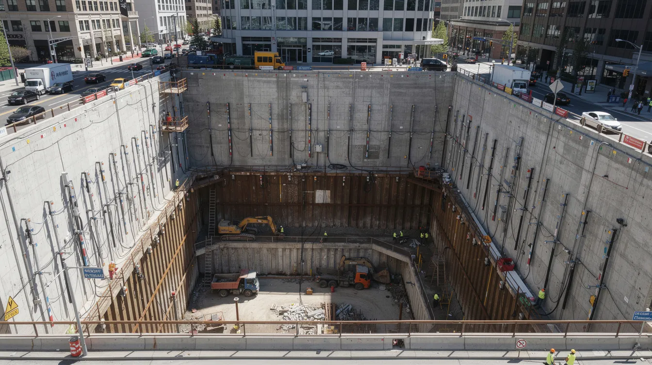
Understanding Instrumentation Monitoring Plans
Instrumentation monitoring plans are systematic monitoring frameworks that ensure construction safety, validate geotechnical design assumptions, and maintain regulatory compliance throughout every critical stage of building works. They form the backbone of risk management for any project where ground conditions, structural elements, or adjacent buildings could be adversely affected by construction activity.
Definition and Purpose of Site Investigation
An instrumentation monitoring plan is a formally documented scheme specifying the types, locations, and density of monitoring instruments deployed on a construction site, along with the frequency of readings, allowable movement thresholds, and emergency protocols. In the Singapore context, these plans serve three core purposes: safety verification (confirming that ground and structural behaviour remain within acceptable limits), design validation (checking that actual conditions match geotechnical parameters assumed in design calculations), and risk mitigation (providing early warning when conditions deviate from predictions).
The I&M plan must specify monitoring strategies including instruments, baseline readings, and monitoring frequency. This connects directly to BCA’s building control framework and its overarching objective of protecting public safety during and after construction.
Regulatory Framework
The Building Control Act (Chapter 29) and Building Control Regulations 2003 establish the statutory foundation for I&M plan requirements. Under Regulation 10A of the BCR, geotechnical building works plans must contain, “where applicable,” instrumentation and monitoring plans as part of the particulars to be shown in geotechnical building works plans. BCA requires structural plan approval before construction begins, and the I&M plan is an integral part of this approval process.
Specific project types triggering mandatory I&M planning include:
-
ERSS and deep excavation exceeding 6 metres in depth or height
-
Tunnelling works with tunnel diameter, width, or height exceeding 2 metres
-
Foundation works for buildings of 30 storeys or more
-
A&A works involving an extension where the structural changes may affect geotechnical or structural behaviour
-
Any earth retaining works adjacent to sensitive structures or critical utilities
The submission requirements for Instrumentation and Monitoring plans must satisfy strict criteria established across these regulations, BCA advisory notes, and approved documents referencing standards such as BS 5930, SS EN 1997-2, and BS 1377.
Types of I&M Plans Required
Different construction activities demand tailored monitoring approaches, including complex or sensitive demolition works where pre-start planning must define safety controls, structural support, and monitoring before work begins. Excavation monitoring plans for basement construction and deep trenches focus on lateral wall movement, base heave, and struts force measurement. These are particularly critical for ERSS schemes involving sheet piles, ground anchors, or soil nailing systems.
Settlement monitoring plans address the impact on adjacent structures and utilities. Plans must show the layout and locations of neighbouring structures and critical utilities, with instruments positioned to capture differential settlement, tilt, and vibration effects on buildings within the zone of influence. ERSS is required for basement excavation and slope stabilisation, making settlement monitoring an essential companion to any earth retaining scheme.
Understanding these requirements in detail is essential for preparing submissions that meet BCA’s technical and procedural standards – which we examine next.
BCA Submission Requirements for I&M Plans
Building on the regulatory framework, the following sections detail exactly what documentation, technical specifications, and professional endorsements must accompany every I&M plan submission to BCA.
Mandatory Documentation
The I&M plan submission must include several categories of documentation, each serving a distinct compliance function:
Instrument layout plans must show precise locations and types of monitoring equipment on both plan view and section view, relative to the excavation perimeter, ERSS alignment, and neighbouring structures. Instrumentation and monitoring plans must include layouts showing the site boundaries and distances to neighbouring structures. Complete schedules for monitoring must include the types and installation locations of monitoring devices – covering inclinometers, piezometers, settlement markers, tiltmeters, strain gauges, and groundwater level sensors.
Monitoring methodology statements must detail data collection frequencies and procedures across all construction phases. Defined schedules for monitoring must be established across pre-construction, active construction, and post-construction phases. The plan must outline baseline readings and monitoring frequency during construction phases, specifying who collects data, how it is processed, and how validity is confirmed.
Trigger level tables must specify numerical trigger values for monitoring including Alert, Action, and Work Suspension levels. Monitoring thresholds must explicitly state allowable building and ground movement criteria and trigger stages. For example, lateral wall deflection might have an Alert threshold at 25 mm, an Action threshold at 35 mm, and a Work Suspension threshold at 50 mm – though actual values depend on project-specific assessment.
Emergency response protocols detail the sequence of actions when trigger levels are exceeded. Regular data submittals and immediate notification protocols must be included for monitoring. Contingency and Remedial Action Plans must be included for breaches of monitoring thresholds, outlining protective works for adjacent structures, emergency underpinning, or temporary shoring.
Submissions must also include architectural and structural drawings alongside the I&M plan, as well as a comprehensive site investigation report documenting subsurface conditions, geological information, and groundwater assessment. Where relevant to the project scope, this documentation may also support CSC or Temporary Occupation Permit compliance at project completion stages.
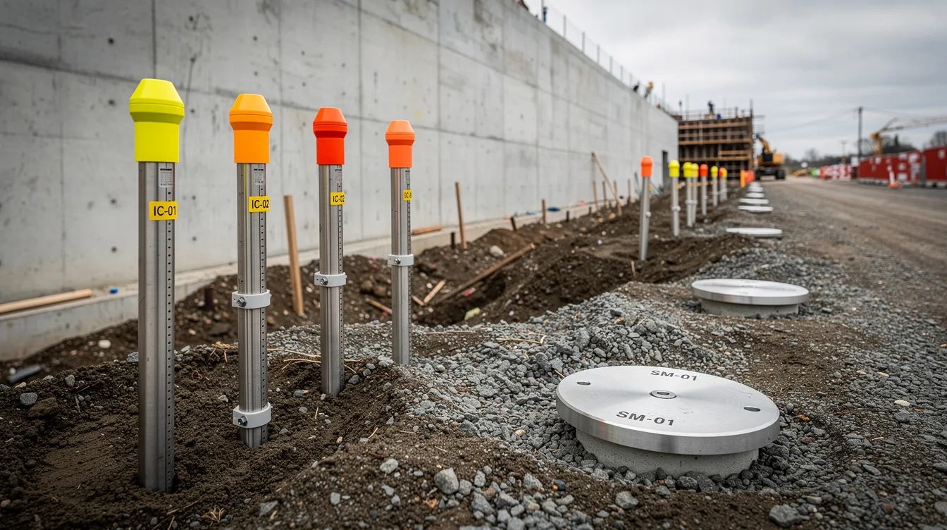
Technical Specifications
Instrument accuracy requirements are context-dependent but must be appropriate to the tolerances being monitored. Settlement gauges typically require accuracy to 0.1 mm or better; inclinometers need sub-millimetre resolution per metre of casing; pore pressure sensors must cover the expected range of groundwater conditions. All instruments require calibration certificates in accordance with applicable standards.
Data transmission specifications for real-time monitoring systems must address communication protocols, data storage, backup procedures, and cybersecurity measures. For projects using ARTMS, the plan must describe sensor connectivity (cellular, fibre, or wireless backhaul), cloud platform architecture, dashboard access controls, and data retention policies.
Installation method statements must describe how each instrument type will be installed, protected from damage during construction, and maintained throughout the monitoring period. Protection measures for instrument cables, sensor housings, and reference points are essential – particularly on active construction sites where heavy machinery and sequence of works can compromise instrument integrity.
Professional Endorsement Requirements and Singapore Accreditation Council Recognition
Drawings must be prepared and endorsed by a Qualified Person and checked by an Accredited Checker. Specifically, PE (Geotechnical) endorsement is mandatory for all I&M plan submissions, including ERSS submissions. The endorsement must include the qualified person’s signature, certificate pages, and proper number and pagination in accordance with BCR requirements.
An Independent Checker is required for higher-risk ERSS submissions – typically projects involving deep basements adjacent to sensitive structures, tunnelling beneath existing buildings, or excavation near critical infrastructure. This independent checking requirement provides an additional layer of assessment to verify that instrument density, trigger levels, and contingency measures are technically sufficient.
Firms conducting instrumentation and monitoring must often be inspection bodies accredited under the Singapore Accreditation Council (SAC) under the “Instrumentation & Monitoring” scheme, ensuring technical competence and adherence to quality standards. Approval of the I&M plan requires ongoing monitoring and assessment by the Qualified Person throughout the project lifecycle.
With submission requirements established, the next critical consideration is how to design an optimal instrument layout and integrate modern real-time monitoring technology.
Instrument Layout Density and ARTMS Integration
Modern monitoring practice increasingly demands both strategically dense instrument placement and automatic real-time monitoring system integration. This section addresses how to plan instrument layout for comprehensive coverage and how ARTMS transforms compliance monitoring from periodic checking into continuous risk management.
Instrument Layout Planning
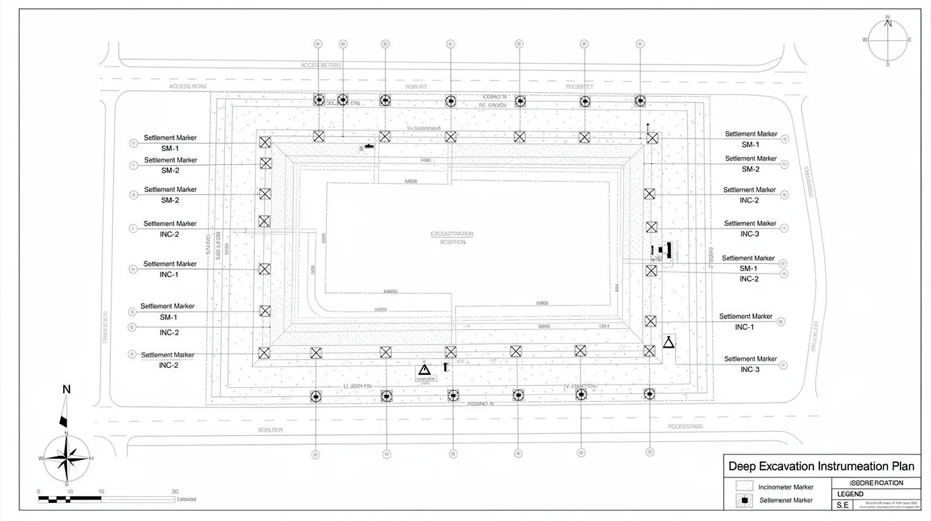
Instrument layout density is not prescribed by BCA through a simple “one instrument every X metres” rule. Instead, layout must be risk-based – calibrated to excavation depth, proximity to sensitive structures, geological conditions, and project complexity. The following stepped approach reflects current best practice:
Step 1: Site assessment and risk zone identification. Begin with thorough site investigation to map subsurface conditions, identify geotechnical parameters, and classify zones by risk level. Areas adjacent to existing buildings within the zone of influence, utility corridors, and locations with variable ground conditions receive the highest instrument density. Instrumentation and monitoring plans must include layout and location of neighbouring structures relative to the works.
Step 2: Instrument type selection based on monitoring objectives. Monitoring instruments must include devices such as inclinometers, piezometers, and settlement markers. For ERSS involving struts and ground anchors, strain gauges on structural support members are critical. For slope stabilisation involving soil nailing, inclinometers along the slope face and piezometers monitoring pore water pressures are essential. Selection must match each instrument to the specific parameter it monitors – lateral movement, vertical settlement, groundwater pressure, structural load, or tilt.
Step 3: Layout optimisation for comprehensive coverage. Practical density benchmarks from approved projects provide useful guidance:
-
Basement excavation adjacent to existing buildings within 5 m: Settlement markers every 2–3 m along the shared boundary; inclinometers every 10–15 m along retaining wall alignments; piezometers at 20–30 m intervals both behind and in front of the wall to capture groundwater gradients
-
Tunnelling works exceeding 2 m span: Monitoring points along the tunnel axis at 10–25 m longitudinal spacing with transverse arrays; sensors at key heading and face locations
-
Slopes exceeding 6 m height: Inclinometer sections spaced to capture movement mechanisms; rainfall-induced pore pressure sensors at intervals downslope
These density benchmarks increase significantly for projects near heavy civil infrastructure, such as MRT stations, heritage buildings, or critical utilities.
Step 4: Integration points for ARTMS connectivity. During layout planning, identify which instruments will feed into automatic real-time monitoring systems. Sensors requiring real-time data transmission – typically those in the highest risk zones – need power supply access, communication infrastructure, and weatherproof housings designed into the layout from the outset.
ARTMS Integration Requirements
The comparison between manual monitoring and automatic real-time monitoring systems reveals why ARTMS adoption is accelerating across Singapore’s construction industry, particularly for high-risk geotechnical works:
|
Criterion |
Manual / Periodic Monitoring |
Automatic Real-Time Monitoring (ARTMS) |
|---|---|---|
|
Data collection frequency |
Daily, weekly, or fixed interval inspections |
Continuous – hourly, sub-hourly, or minute-by-minute |
|
Response time to anomalies |
Hours to days between measurement and detection |
Immediate detection with automated alerts |
|
Data resolution |
Lower resolution; gaps between readings may miss transient events |
High resolution; captures spikes, trends, and transient behaviour |
|
Cost profile |
Lower upfront cost; requires ongoing manpower |
Higher capital and installation cost; reduced long-term labour |
|
Compliance benefit |
Satisfies BCA minimum requirements |
Exceeds requirements; provides stronger proof of compliance during BCA inspection |
|
Risk of data loss |
Vulnerable to human error, delayed response |
Vulnerable to system failure; requires redundancy and power backup |
Real-time data transmission protocols must specify how sensor data flows from field instruments to cloud platforms, including communication backhaul (cellular or fibre), data validation algorithms to distinguish genuine ground movement from instrument drift, and secure dashboard access for qualified person supervisors, site supervisors, and regulatory reviewers.
Alert notification systems must tie directly to the trigger level tables submitted to BCA. When readings approach Alert levels, automated notifications reach the supervising QP and project team. When Action or Work Suspension thresholds are breached, the system must trigger immediate notification protocols – including notification to the Commissioner of Building Control “as soon as practicable” as required under BCR Regulation 37(3).
BCA has mandated continuous monitoring of soil removal volumes and ground movements for tunnelling projects, and automatic monitoring with real-time data has become the expected standard for any project where sinkhole risk or ground distress could develop rapidly. For high-risk works – deep basements, ERSS adjacent to sensitive structures, underground transit – the trend clearly favours ARTMS integration as the baseline rather than the exception.
The choice between manual and automatic systems should be driven by project risk profile: standard foundation works may require only periodic manual monitoring, while deep excavation near occupied buildings warrants full ARTMS deployment with redundancy built into every critical sensor location.
Back-Analysis Protocols
When instrumentation reveals that measured movements exceed predicted values, rigorous back-analysis protocols become a regulatory requirement – not an optional engineering exercise. Under Regulation 10A and Part III of the BCR, the supervising QP must “assess monitoring results… ensure geotechnical aspects are within design assumptions and parameters at every critical stage… and review or modify the design so as to ensure its adequacy as appropriate.”
The back-analysis sequence follows a structured procedure:
-
Immediate notification: When allowable movement, vibration, or groundwater changes exceed trigger levels, the supervising QP and builders must notify the Commissioner of Building Control as soon as practicable. Construction in the affected area may need to be suspended pending assessment.
-
Data validation and instrument verification: Before concluding that ground behaviour has deviated from predictions, verify instrument function. Check for sensor drift, cable damage, environmental interference, or installation error. Cross-reference readings across multiple instruments to confirm whether the anomaly is localised or systemic.
-
Model comparison and parameter updating: Compare measured behaviour against the predictive models used in design calculations. Identify discrepancies in assumed soil modulus, boundary conditions, groundwater pressures, or seepage patterns. Recalculate expected deformations under updated geotechnical parameters to determine whether the deviation is within manageable bounds or requires design modification.
-
Design revision and remedial measures: If back-analysis confirms that actual conditions exceed design capacity, modifications must be implemented. This might include reinforcing support systems (additional struts, ground anchors, or enhanced wall sections), altering the excavation sequence, installing additional drainage or groundwater control measures, or limiting surcharge loads near the excavation.
-
Documentation and reporting: Every back-analysis must be thoroughly documented. Reports must record the exceedance event, instrument data, causes identified, remedial actions conducted, updated analysis, design modifications, revised monitoring plan, and follow-up readings. These reports are submitted to BCA periodically – typically monthly during active construction via Annex E Forms for ERSS – and immediately when incidents trigger notification requirements.

Common Challenges and Solutions
Even well-prepared I&M plans encounter practical obstacles during submission and implementation. The following addresses the most frequent challenges faced by project teams.
Instrument Layout Approval Delays
Under-specified I&M plans are the primary cause of submission delays. Missing trigger values, unclear instrument positions, or insufficient justification for layout density trigger BCA queries that can stall approval for weeks.
Solution: Engage the qualified person (Geotechnical) early in the design process, well before submission deadlines. Use benchmarking data from recent approved submissions for comparable project types. Ensure instrument layout drawings explicitly show site boundaries, distances to neighbouring structures, and the relationship between monitoring points and risk zones. Coordinate I&M plan submission with the main structural plan application to avoid sequencing conflicts. Note that submission fees for ERSS range from S$3,000 to S$15,000 depending on project size and complexity, while fees for A&A submissions range from S$1,500 to S$10,000 – budget accordingly.
ARTMS System Integration Issues
Automatic monitoring systems sometimes face integration failures due to poor network connectivity, power supply limitations, incompatible sensor protocols, or insufficient data management infrastructure.
Solution: Design the instrument network to include power backup (battery or solar), redundant communication backhaul (dual cellular modems or cellular plus fibre), weatherproof and tamper-resistant housings, and standardised data protocols compatible with cloud dashboards. Conduct connectivity testing during site investigation phase before finalising instrument locations. Specify data validation algorithms that automatically flag anomalous readings for manual verification, distinguishing instrument failure from genuine ground events. As BCA moves toward digital submission through CORENET-X – mandatory for all new buildings from 1 October 2026 – data standardisation will become even more critical. CORENET-X requires BIM-based submissions, and BIM model data is required for projects over 5,000 sqm GFA, with BCA mandating federated information across architectural and structural disciplines.
Trigger Level Exceedance Management and Periodic Structural Inspection
When trigger levels are exceeded, confusion about responsibilities, slow communication, and poorly defined contingency plans can escalate minor exceedances into serious incidents.
Solution: Pre-define clear escalation chains in the I&M plan: who is notified at each trigger stage (Alert, Action, Work Suspension), response timeframes, and specific contingency measures for each scenario. Ensure dashboards provide real-time visibility to all stakeholders. Maintain pre-approved contingency designs (e.g., additional struts pre-fabricated, emergency grouting equipment on standby) so remedial action can be carried out without design delay. Document all exceedances meticulously – these records become part of compliance evidence during BCA inspection and may be reviewed during regularisation submissions, which can cost between S$2,500 and S$20,000.
Conclusion and Next Steps
Successful I&M plan submission to BCA requires comprehensive documentation, risk-calibrated instrument layout planning, and thoughtful ARTMS integration – all endorsed by qualified professionals and supported by robust back-analysis protocols. The plan is not a static document; it must be maintained, updated, and actively managed throughout the entire construction lifecycle from pre-construction baseline readings through to statutory completion.
To move forward on your I&M plan submission:
-
Engage a PE (Geotechnical) early to lead plan design and provide mandatory endorsement
-
Commission a thorough site investigation to establish geotechnical parameters and identify risk zones for instrument density planning
-
Prepare instrument layout drawings with clear trigger level tables, monitoring frequency schedules, and contingency measures
-
Specify ARTMS requirements for high-risk zones, including real-time data transmission, alert protocols, and system redundancy
-
Coordinate with your main structural plan submission to ensure I&M plan approval aligns with overall BCA approval timelines
-
Verify SAC accreditation of your instrumentation and monitoring inspection bodies
Related topics worth exploring include ERSS design and submission requirements for projects involving earth retaining works, periodic structural inspection obligations for buildings over 13 years old (mandatory every 5 years for non-residential and every 10 years for residential buildings, conducted by a Professional Engineer (PE) Civil with inspection reports submitted to BCA), and ongoing monitoring compliance through the construction and post-construction phases toward temporary occupation permit milestones.
Additional Resources
-
BCA Guidelines for Structural Plan Applications – comprehensive submission guidance including geotechnical requirements
-
BCA Advisory Note 1/09 for ERSS – foundational circular on ERSS instrumentation and monitoring expectations
-
BCA Academy Certification Course in Instrumentation and Monitoring – professional development covering sensor selection, data interpretation, and real-time monitoring practice
-
Singapore Construction Compliance Checklist – cross-reference your I&M plan requirements against broader regulatory obligations
-
Structural Inspection Tips for 2026 – guidance on psi requirements and inspection standards for existing structures