
Key Takeaways
Finite element analysis (FEA) helps modular construction teams test structural behavior before fabrication, lifting, transport, and installation. In Singapore, its value is greatest when it is connected to DfMA decisions, authority requirements, and practical fabrication constraints.
- FEA links structural design with manufacturing and assembly decisions.
- PPVC and MET steel modules require different modeling priorities.
- Construction-stage analysis captures temporary conditions that permanent design may miss.
- High-rise projects need coordinated checks for movement, fire, wind, and abnormal loads.
- A controlled FEA-to-fabrication workflow improves traceability and reduces avoidable rework.
How FEA supports DfMA in Singapore’s modular construction sector
FEA gives engineers a way to examine how a modular system behaves as it moves from concept to factory and then to site. That makes it a natural companion to DfMA planning, where manufacturing constraints, assembly methods, and structural performance are considered together. The analysis is not an isolated calculation; it is a decision-making tool that can influence module dimensions, connection details, lifting points, and sequence of work.
For Singapore megaprojects, the approach is particularly useful because repetition and tight sites magnify both good and poor design choices. A small interface problem repeated across hundreds of modules can become a major programme issue. Conversely, a well-tested standard detail can provide consistency without encouraging careless duplication.
Linking design, manufacturing, and assembly decisions
A modular structural model should answer practical questions as well as theoretical ones. Can the module be fabricated without difficult access or excessive welding? Will temporary lifting points introduce stresses that are absent in the completed building? Can workers align and connect the unit within the available tolerance? These questions connect analysis to the decisions made by designers, fabricators, logistics teams, and installers.
The useful output is therefore more than a contour plot. Engineers should identify the design assumptions that affect production, such as connection stiffness, support locations, lifting geometry, and the sequence in which loads enter the module. When those assumptions are visible early, a change in fabrication or assembly can be assessed before it becomes a site variation.
Managing repetition, standardization, and project scale
Repetition creates an opportunity for standardization, but it does not remove the need for engineering judgment. Modules that appear identical may experience different behavior because of openings, service penetrations, façade attachments, fit-out weights, or their location within the tower. FEA can help classify module families and determine where one representative model is appropriate and where a separate check is needed.
A sensible model hierarchy might include a global model for overall load paths, refined connection models for critical interfaces, and local studies for openings or lifting brackets. This avoids treating every module as a completely new problem while still protecting the project from false assumptions about uniformity.
Identifying structural risks before fabrication
FEA is most valuable when it exposes a risk while the design can still change. Potential concerns include excessive distortion during lifting, local stress concentrations around openings, connection slip, slab vibration, frame instability, and unexpected load transfer between modules and the primary structure. Early analysis also gives the project team time to review whether a detail is buildable, inspectable, and accessible for maintenance.
The result should be expressed in engineering terms that support action. Rather than simply reporting that a region is highly stressed, the team should identify the likely cause, the relevant load stage, the sensitivity of the result, and the available design responses. This turns simulation into a controlled design conversation.
Balancing material efficiency, robustness, and constructability
Material efficiency cannot be judged from member weight alone. A lighter section may require tighter tolerances, more complicated connections, additional temporary bracing, or slower fabrication. On a large project, those secondary effects can outweigh the saving in steel or concrete.
A better DfMA review compares strength, stiffness, stability, connection behavior, fabrication effort, transport limitations, and erection sequence. Constructability must remain visible in the optimization process. The preferred solution is usually the one that performs reliably across the full chain of manufacture, movement, assembly, and occupation—not simply the one with the lowest theoretical material quantity.
Establishing the right FEA model for modular systems
The quality of an FEA result depends heavily on the model that produces it. Modular construction introduces changing supports, semi-rigid interfaces, temporary lifting conditions, and discontinuous load paths that are easy to oversimplify. A model should therefore be developed around the decisions it needs to support, rather than around visual detail for its own sake.
Geometry, material behavior, mesh density, contact assumptions, and load application all need to be recorded. The model should also distinguish between temporary and permanent conditions. This is where professional engineering review matters: a technically sophisticated model can still mislead if its boundary conditions do not resemble the real project.

Defining geometry, materials, and boundary conditions
The geometry should capture features that materially affect stiffness and load transfer, including frame members, slabs, walls, braces, openings, penetrations, supports, and connection regions. Simplification is acceptable when its effect is understood and documented. It becomes risky when small details are removed without checking whether they control local behavior.
Material definitions should reflect the selected system and the intended limit state. Linear elastic analysis may be adequate for an initial stiffness study, while nonlinear material behavior, geometric imperfections, contact, or staged loading may be needed for stability and ultimate-strength questions. Boundary conditions should represent actual restraints rather than idealized fixed supports used for convenience.
Representing module-to-module and module-to-core connections
Connections often govern whether modular units act independently, as a group, or as part of a larger structural system. Bolted joints, welded details, bearing interfaces, tie elements, and brackets may have different stiffness, slip, ductility, and failure modes. Their behavior should be represented at a level appropriate to the question being asked.
The interface with a reinforced-concrete core deserves particular care. Differential stiffness, construction tolerances, vertical shortening, and horizontal movement can alter force distribution between the modules and the core. Where a connection is modeled as rigid, pinned, or spring-supported, the assumption should be justified and tested through sensitivity studies.
Applying realistic loading and load combinations
A modular unit experiences more than its final gravity load. The analysis may need to consider self-weight, imposed loads, façade and MEP loads, lifting forces, transport accelerations, wind during erection, temporary supports, installation tolerances, and accidental effects. Not every load belongs in every combination, but each relevant construction stage should have a clear rationale.
Load paths should be followed from the point of application to the supports and interfaces. This is especially important when a floor slab, wall, frame, or lifting lug carries a load that is not present in the completed configuration. Serviceability checks should accompany strength checks where deflection, vibration, alignment, or cracking could affect installation or occupancy.
Calibrating models against tests, codes, and engineering judgment
Calibration may involve component tests, connection tests, material data, previous project experience, code provisions, or comparison with simplified hand calculations. The aim is not to force the model to produce a preferred answer. It is to understand whether the model behaves plausibly and whether its sensitivity matches the physical system.
Engineering judgment remains necessary when test conditions do not reproduce the full building. A test may clarify connection stiffness but not long-term movement, or it may show local failure without resolving the global load path. The final report should state what has been validated, what remains uncertain, and how conservatism has been applied.
FEA applications for PPVC modules
Prefabricated Prefinished Volumetric Construction (PPVC) modules are completed or substantially completed away from their final position, so their structural behavior changes several times before occupation. A module may be lifted at discrete points, supported during transport, placed on temporary bearings, and finally connected into a larger building. Each state deserves a deliberate check.
The analysis should account for the relationship between the structural frame, walls, slabs, finishes, fixtures, and services. A module that is adequate in its final position can still experience unacceptable distortion during handling. Conversely, adding unnecessary reinforcement for a temporary condition can reduce the benefits of off-site production.
Assessing lifting, transportation, and installation stages
Lifting analysis begins with the rigging arrangement, centre of gravity, lifting points, and expected load-sharing behavior. Unequal sling forces, local plate bending, torsion, and distortion can become critical when the module is not perfectly balanced. Transport introduces additional effects from acceleration, braking, uneven support, and restraint.
Installation analysis should then examine the transition from crane support to bearing or connection support. The sequence matters because one corner or edge may receive load before the rest of the module is fully seated. Clear assumptions about lifting tolerances and support contact make the results more useful to the logistics and site teams.
Checking floor slabs, walls, frames, and load-transfer paths
PPVC modules often combine several structural components that work differently during handling and in service. Floor slabs may span between walls or frames, while walls can act as diaphragms, bearing elements, or transport-sensitive panels. Openings and service zones interrupt otherwise simple load paths.
The model should trace gravity and lateral actions through the module and into its connections. Local reinforcement or framing may be needed where concentrated reactions occur. The review should also consider whether finishes, partitions, and fixed equipment add permanent weight or alter the distribution of imposed loads.
Evaluating temporary and permanent support conditions
Temporary supports are not merely placeholders in the analysis. Their spacing, stiffness, contact area, and installation sequence can control slab stresses and local crushing. Permanent bearings and connection assemblies may behave differently, particularly where grout, shims, bolts, or welds are introduced after placement.
Comparing support conditions helps identify details that are safe only under perfect seating. It can also reveal whether a module needs a temporary prop, a minimum bearing length, or a prescribed installation sequence. These findings should be transferred into method statements and inspection requirements.
Investigating vibration, deflection, and serviceability performance
Strength is only one part of PPVC performance. Excessive deflection can interfere with door operation, finishes, façade interfaces, or service connections. Floor vibration may affect occupant comfort, equipment operation, or perceptions of quality even when stresses remain within acceptable limits.
Dynamic properties, span arrangements, damping assumptions, and fit-out mass should be reviewed together. Serviceability criteria need to match the intended use of the space and the sensitivity of connected components. Where results are close to a limit, the design team should examine stiffness, support continuity, and load distribution rather than relying on a single numerical adjustment.
Addressing changes caused by openings, MEP systems, and fit-out loads
Openings for ducts, pipes, risers, and access panels can interrupt walls, slabs, and framing. MEP systems may also add concentrated loads or require supports that were not present in the initial structural scheme. Fit-out changes can be just as significant when the module is designed around a standard load allowance.
An updated analysis is warranted when the change affects a primary load path, removes reinforcement, adds a significant attachment, or alters the module’s centre of gravity. Early coordination is preferable to field cutting, where local damage and undocumented changes can compromise both performance and traceability.
FEA applications for MET steel modules
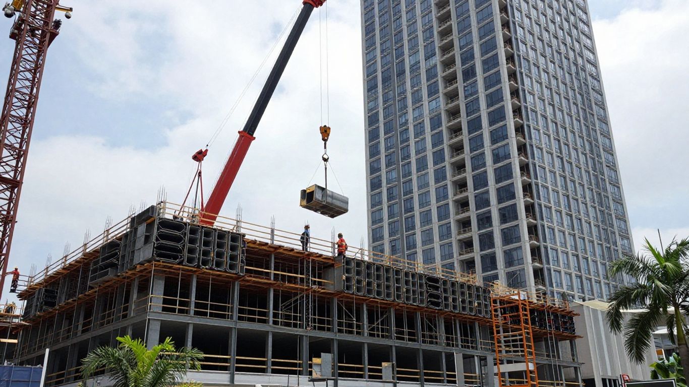
MET steel modules rely on steel framing and associated floor, wall, and connection systems to provide strength and stiffness. Their relatively light weight can support efficient transport and erection, but slender members and thin connection components may be sensitive to instability. The analysis must reflect both the completed building and the stages before the frame is fully restrained.
Steel behavior is often controlled by interaction between members, plates, connections, and composite elements. A global model can identify force distribution, while local models may be necessary for buckling, connection prying, weld regions, or bearing zones. The right level of detail depends on the design question and the required approval evidence.
Analyzing steel frame stability and local buckling
Frame stability checks should consider effective lengths, lateral restraint, second-order effects, imperfections, and construction-stage bracing. Local buckling in webs, flanges, plates, and hollow sections can reduce resistance before a member reaches its nominal plastic capacity. These effects are particularly relevant where modules have large openings or long unsupported edges.
Eigenvalue analysis can help identify likely instability modes, but it should not be treated as the final capacity assessment. Geometric imperfections and nonlinear analysis may be required to understand post-buckling behavior and interaction between local and global modes. Results should be interpreted with reference to the actual fabrication tolerances and restraint conditions.
Designing bolted, welded, and inter-module connections
Connections transfer more than the design gravity reaction. They may also carry shear, tension, moment, erection forces, accidental actions, and compatibility effects from differential movement. Bolted joints require attention to slip, bearing, bolt group behavior, and access for tightening; welded joints require attention to weld geometry, restraint, and heat-affected regions.
Inter-module connections should be assessed as part of the complete load path. A local connection model can identify prying, block shear, plate bending, weld concentration, and bolt interaction that a beam-element model cannot show. The connection detail must also permit inspection, installation, and replacement where required.
Evaluating composite floors and steel–concrete interaction
Where concrete slabs act with steel beams, the degree of composite action affects stiffness, vibration, deflection, and force distribution. The analysis should state whether interaction is full, partial, or intentionally neglected, and should account for shear connectors, construction stages, cracking, and differential deformation where relevant.
The floor may behave differently while concrete gains strength than it does after the module is connected to neighboring units. Temporary propping, deck continuity, and interface detailing can therefore alter the final response. A staged model is useful when construction sequence has a meaningful effect on composite behavior.
Checking fire exposure and temperature-dependent behavior
Fire analysis changes the material properties and stiffness assumptions used in a room-temperature model. Steel strength and stiffness reduce as temperature rises, while restraint from slabs, neighboring modules, and connections can redistribute forces. Protection systems and compartment boundaries must be included in the engineering assessment where they influence the temperature history.
The review should consider member stability, connection response, composite action, deformation compatibility, and the intended fire resistance period. Thermal effects can also impose forces on interfaces that are not obvious in a gravity-only model. Fire engineering assumptions should remain consistent with the project’s fire strategy and approval pathway.
Optimizing member sizes for fabrication and erection
Member optimization should weigh structural capacity against cutting, drilling, welding, coating, transport, lifting, and erection requirements. Very small changes in section size may create new connection details or complicate standardization. The most efficient frame is therefore not necessarily the lightest frame.
A useful process is to compare a limited number of practical alternatives and record their effects on weight, stiffness, connections, temporary stability, and fabrication effort. This supports transparent value engineering without losing sight of the tolerances and sequence needed on site.
Simulating construction and assembly sequences
Modular projects are assembled through a sequence of temporary states, and those states can govern the design. FEA can test the effects of lifting, partial restraint, temporary bracing, uneven support, and changing load paths before crews encounter them. This is especially relevant where modules interface with a central core, façade, or building services.
Construction simulation should be developed with the contractor and fabricator rather than handed over after design is complete. The model is most useful when it reflects actual crane positions, rigging arrangements, support details, access constraints, and planned tolerances.
Modeling module lifting and crane-induced forces
Crane lifting introduces forces that depend on rigging geometry, acceleration, rotation, and load sharing. A rigid-body assumption may be suitable for a preliminary check, but local frame and lifting-point behavior often requires a more detailed model. Dynamic amplification should be selected carefully and related to the proposed lifting method.
The analysis should examine both the module and the lifting accessories or their connection regions. Local yielding, distortion, and unintended contact can affect safe handling even when the final structural system is adequate. The findings should inform lifting plans, not sit only in the calculation package.
Assessing temporary bracing and stability during erection
A module may be stable once connected to the core and adjacent units but vulnerable while standing alone or partially attached. Temporary braces, props, restraints, and exclusion zones should be modeled as part of the erection condition. Wind during installation can be more critical than the same wind acting after enclosure.
The sequence should identify the point at which the module becomes self-supporting and the checks required before releasing the crane. It should also show whether a brace can be installed, inspected, and removed without conflicting with façade or MEP work.
Coordinating module interfaces with cores, façades, and MEP services
Interfaces are where structural, architectural, and building-services decisions meet. Movement joints, brackets, edge beams, fire stopping, façade anchors, risers, and service connections can all compete for limited space. FEA can identify movement and reaction demands, but the results must be coordinated in the shared model and details.
Particular attention should be given to differential shortening, horizontal drift, bearing tolerances, and the sequence in which interfaces are closed. A connection that works structurally may still be impractical if it cannot be accessed after the façade or services are installed.
Using 4D BIM to connect FEA findings with construction sequencing
4D BIM can visualize when a module is lifted, supported, connected, enclosed, and loaded. Linking those states to FEA results helps the team see which assumptions belong to which activity. This supports concurrent engineering and makes changes in sequence easier to assess.
The value is not the animation itself. The value lies in connecting a dated construction activity to a structural state, a temporary condition, or a required inspection. A sequence review should therefore identify decisions, hold points, and responsible parties rather than simply display movement through the model.
Reducing rework through early clash and tolerance analysis
Clash detection should include more than obvious geometric collisions. Tolerance analysis can reveal whether bolt holes align, whether bearing surfaces have adequate adjustment, and whether services remain installable after expected movement. These checks are particularly valuable when modules are fabricated off site and cannot be easily modified at the point of installation.
A short, coordinated review can prevent a long chain of corrections. The project team should record which clashes are design issues, which are fabrication issues, and which require a controlled site tolerance. That classification makes the response clearer and protects the intended load path.
FEA considerations for high-rise Singapore megaprojects
High-rise modular buildings combine repeated units with a primary structure that responds to wind, gravity, movement, and, where relevant, accidental or seismic actions. The greater the height and complexity, the more important it becomes to distinguish module behavior from whole-building behavior. Local analyses should feed into, and remain compatible with, the global structural model.
Singapore projects also require attention to tropical environmental conditions, fire safety, durability, regulatory review, and dense urban interfaces. Analysis should be planned around the evidence needed for design decisions and authority submissions, with assumptions traceable from the first model to the final endorsed documents.
Accounting for wind, seismic, impact, and accidental loads
Wind can govern both the completed tower and temporary erection stages. The analysis should consider global lateral response, module-to-core force transfer, façade and connection movements, and local effects around exposed elements. Seismic actions may be less dominant in some Singapore designs than wind, but the project’s applicable code basis and structural system still determine what must be checked.
Impact and accidental actions require a clear definition of the event and the intended robustness strategy. A generic increase in load is not a substitute for understanding the affected load path, available alternate paths, and consequences of local damage.
Evaluating progressive collapse and abnormal load scenarios
Progressive-collapse assessment examines whether local damage can trigger disproportionate failure. For modular systems, the review may involve loss of a module connection, damage to a supporting element, or disruption of a key interface. The response depends on continuity, tying, alternate load paths, and the ability of surrounding components to redistribute demand.
The scenario should be realistic and consistent with the project’s robustness requirements. Nonlinear analysis may be appropriate for important cases, but the model still needs credible connection behavior and staged removal assumptions. Conclusions should explain the extent of demonstrated resistance rather than imply universal protection.
Checking differential movement between modules and primary structures
Modules may shorten, expand, or drift differently from a concrete core, transfer structure, or perimeter frame. Sources include elastic and creep shortening, temperature, shrinkage, wind drift, construction tolerances, and support settlement. If these movements are restrained unintentionally, connection forces and non-structural damage can increase.
FEA can compare movement demands at bearings, ties, façade brackets, service connections, and fire-stopping interfaces. The design response may involve flexible details, sliding interfaces, movement joints, installation allowances, or a deliberate redistribution of restraint. The important point is to make movement a designed feature rather than an afterthought.
Integrating fire safety, durability, and environmental conditions
Fire resistance, corrosion protection, moisture exposure, temperature changes, and maintenance access influence the long-term performance of modular systems. Steel protection may be interrupted at connections, while concrete elements may develop cracks or durability concerns at exposed interfaces. FEA does not replace detailing standards or inspection, but it can clarify temperatures, stresses, movements, and critical regions.
Singapore’s climate also makes water management and corrosion control practical design concerns. Drainage, sealants, coatings, ventilation, and access for inspection should be coordinated with structural details. A calculation that ignores the environment may be correct only for an idealized short-term condition.
Aligning analysis with Singapore codes and authority submissions
The project team should establish the governing Singapore Standards, Eurocode provisions, National Annexes, BCA requirements, fire provisions, and submission responsibilities at the outset. The analysis report should identify load factors, combinations, material properties, acceptance criteria, and departures from standard assumptions.
Professional Engineer review is essential where calculations support statutory submissions or endorsements. The submission package should be internally consistent across drawings, models, design statements, connection details, and construction information. Clear documentation reduces questions during review and makes later revisions easier to control.
Building an efficient FEA-to-fabrication workflow
An efficient workflow does not mean producing the largest model or automating every decision. It means preserving reliable information as geometry, assumptions, results, and design changes pass between BIM, analysis, detailing, and fabrication. The process should allow the team to see what changed, why it changed, and which checks must be repeated.
This is also where an engineering consultancy can add practical value. Aman Engineering Consultancy documents services including Shop Drawing Production & Tekla 3D, while analysis teams still need to define the approved structural intent that fabrication information must follow. The connection between those activities should be managed rather than assumed.
Setting up model exchange between BIM, analysis, and fabrication platforms
Model exchange should begin with agreed naming, coordinates, units, material grades, member identifiers, connection references, and revision status. Not every object needs to move between platforms, but every transferred object should retain enough identity for comparison and checking. Geometry translation should be tested on a small sample before the full model is exchanged.
A clear ownership matrix helps resolve common ambiguities. The structural model may own member sizes and design forces, the BIM model may coordinate spatial interfaces, and the fabrication model may own shop-level geometry. These boundaries should be agreed before revisions begin.
Applying QA/QC checks to meshes, connections, and results
Quality checks should cover geometry, element connectivity, supports, material assignment, mesh convergence where relevant, load application, combinations, and result extraction. Connection models deserve independent review because small errors in contact, releases, or bolt definitions can materially change the outcome.
A practical review sequence keeps the checks repeatable:
- Confirm geometry, units, materials, releases, and support conditions.
- Compare reactions and global equilibrium with simplified calculations.
- Review mesh quality and refine critical regions where results are sensitive.
- Check connection forces, local stresses, deflections, and governing combinations.
- Record reviewer comments, revisions, and unresolved limitations.
After these checks, the team can distinguish a genuine structural trend from a modeling artifact. That distinction is essential before results are used to change a member, connection, or fabrication detail.
Converting analysis outputs into shop drawings and assembly details
FEA outputs should be translated into information that fabricators and installers can use: member sizes, plate thicknesses, bolt grades and arrangements, weld requirements, stiffeners, lifting points, bearing details, tolerances, and inspection notes. The calculation model is not itself a shop drawing, and a stress contour should never be treated as a fabrication instruction without engineering interpretation.
Where drawing production is required, Aman Engineering Consultancy’s documented C&S Engineering Consultancy service is relevant to the broader coordination of infrastructure and building works. The engineering team should still verify that every drawing reflects the approved analysis assumptions and the latest coordinated model.
Using sensitivity studies to prioritize critical design variables
Sensitivity studies show which assumptions actually control the result. Variables may include connection stiffness, support friction, material strength, lifting-point location, imperfection amplitude, load distribution, or movement allowance. The purpose is not to create endless alternatives, but to focus review effort where uncertainty has practical consequences.
For a repeated modular system, sensitivity findings can guide standard details and identify exceptions. If a result changes substantially with a small tolerance variation, that tolerance belongs in the fabrication and installation control plan. If it barely changes, the project may avoid unnecessary precision or over-modeling.
Documenting assumptions, limitations, and design decisions for approval
A defensible report states the model scope, geometry source, material basis, boundary conditions, load cases, combinations, analysis method, convergence behavior, acceptance criteria, and limitations. It should also identify which construction stages were assessed and which were outside the model. This record helps reviewers understand the evidence rather than infer it from screenshots.
For statutory work, Aman Engineering Consultancy lists Authority Submissions among its professional engineering services. Any submission must remain aligned with the applicable codes, endorsed drawings, and project-specific requirements. Good documentation is not administrative decoration; it is part of demonstrating that the design decision can be followed, reviewed, and responsibly implemented.
Conclusion
FEA becomes most useful in PPVC and MET steel construction when it follows the module through design, fabrication, transport, erection, connection, and service. Combined with disciplined DfMA coordination, realistic temporary-stage modeling, Singapore code alignment, and clear engineering documentation, it can reduce uncertainty without replacing professional judgment. The strongest workflow is practical: model what matters, validate the assumptions, communicate the result, and carry the decision into fabrication and assembly.
Frequently Asked Questions
What is FEA used for in modular construction?
FEA is used to examine stresses, deflections, stability, vibration, connection behavior, and load paths across both temporary construction stages and the completed modular building.
Why should PPVC modules be analyzed during lifting?
Lifting introduces concentrated reactions, uneven sling forces, torsion, and local distortion that may not occur after the module is installed. A final-state check alone can miss these conditions.
How does MET steel analysis differ from PPVC analysis?
MET steel analysis commonly places greater emphasis on frame stability, local buckling, connection behavior, composite action, fire exposure, and the erection sequence, while PPVC analysis often focuses on volumetric walls, slabs, handling, and support transitions.
Are temporary supports included in an FEA model?
They should be included when their stiffness, location, contact, or sequence can affect structural behavior. Temporary supports may govern local stresses before permanent connections are complete.
What information should an FEA report contain?
A report should describe the geometry, materials, boundary conditions, load cases, combinations, analysis method, mesh or idealization, results, acceptance criteria, assumptions, limitations, and design decisions arising from the study.
How can FEA support DfMA decisions?
It can compare module layouts, connection concepts, lifting arrangements, member sizes, tolerances, and construction sequences before fabrication, helping teams consider manufacture and assembly alongside structural performance.
Does FEA replace code checks or professional engineering review?
No. FEA is an analysis method that supports engineering design. Results still need interpretation, code-based verification, coordinated documentation, and review by appropriately qualified professionals where required.