
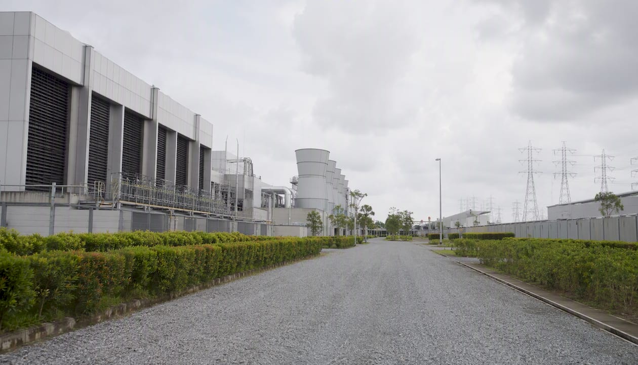
Effective data centers design delivers predictable availability, controlled operating costs, and a 15–20 year scalable platform — provided the project begins with a rigorous alignment of capacity targets, energy strategy, and business objectives before a single drawing is issued.
Verdict at a glance:
- Availability: Target the Uptime Institute Tier classification that matches your service-level objectives — Tier III (N+1 concurrently maintainable) for most enterprise and colocation facilities; Tier IV (2N fault-tolerant) where higher availability is critical.
- Efficiency: Power Usage Effectiveness (PUE) targets typically range in an efficient design from low to mid values achievable with proper economizer and containment design; ASHRAE thermal guidelines set the envelope for safe, efficient operation.
- Scalability: Design for modular readiness from day one — data centers are typically built with a lifespan of multiple years to decades while AI-driven density requirements can change within a single budget cycle.
- Regulatory and community readiness: Permitting timelines in the U.S. are increasingly shaped by community opposition over energy and water use; early stakeholder engagement and an ESG disclosure strategy are no longer optional.
Immediate next steps for decision-makers:
- Align the business case: define capacity, availability, and sustainability targets before engaging designers.
- Conduct pre-feasibility on power access and fiber routes — utility interconnection queues in many U.S. markets now can extend over long periods.
- Begin stakeholder mapping: identify local authorities having jurisdiction (AHJ), utility contacts, and community groups before site selection.
- Engage a qualified data center consultancy to validate site shortlists against USGBC/LEED sustainability targets and ASHRAE thermal criteria.
Key Takeaways
Effective data centers design requires aligning energy strategy, redundancy architecture, and community engagement before detailed design begins — the sequence of those decisions determines both project cost and long-term operational performance.
| Point | Details |
|---|---|
| Align energy strategy first | Confirm power procurement model and utility access before committing to redundancy architecture or MEP design. |
| Secure power and fiber early | Utility interconnection queues in U.S. markets can extend 18–36 months; pre-application must precede site commitment. |
| Match redundancy to SLOs | Tier III (N+1) suits most enterprise and colocation facilities; Tier IV (2N) is justified only where downtime cost warrants the capital premium. |
| Design cooling with headroom | Zone cooling infrastructure and provision for future liquid cooling to avoid full mechanical retrofits as rack density increases. |
| Com for end-to-end delivery | Com provides site feasibility, civil and structural design, MEP coordination, BIM, and commissioning support for U.S. data center projects. |
Table of Contents
- What types of data centers should you build or lease?
- How does the data centers design and construction lifecycle work?
- How do you pick a site and manage grid, water, and community risks?
- What power architecture and redundancy strategy should you use?
- How should you approach cooling and thermal management?
- How do you measure and improve data center energy efficiency?
- When do modular and prefabricated approaches make sense?
- What security, fire safety, and compliance standards apply?
- How do you operate, monitor, and commission a data center?
- What do data center projects typically cost and how long do they take?
- What are the most common data center project mistakes?
- How do you select the right data center design consultancy?
- The methodology and standards Com follows on data center projects
- What practitioners get wrong about data centers design priorities
- Com’s engineering services for U.S. data center projects
- Sources
What types of data centers should you build or lease?
Choosing the right deployment model is the first structural decision in any data center program. The four primary types — enterprise, colocation, cloud/hyperscale, and edge — differ substantially in capital profile, operational control, and time-to-market.
| Type | Typical availability target | Latency profile | Capex vs. opex | Speed-to-market |
|---|---|---|---|---|
| Enterprise (owner-operated) | Tier III or IV | Internal network, flexible | High capex, lower long-run opex | typically multiple months to several years for new build |
| Colocation | Tier III or IV (provider-managed) | Dependent on carrier selection | Low capex, recurring opex | several months for fit-out |
| Cloud / hyperscale | Provider-defined (typically Tier III equivalent) | Region-dependent | Opex-dominant | weeks or less |
| Edge | Tier I–II, often N+1 | Low latency to end user | Moderate capex, distributed opex | several months modular |
Enterprise facilities give organizations full control over security zoning, redundancy architecture, and compliance posture. They carry the highest capital cost and longest delivery timeline, making them appropriate for organizations with stable, long-term workloads and stringent data sovereignty or regulatory requirements.
Colocation transfers facility risk to a specialist operator while preserving control over IT equipment. For organizations entering a new market or scaling quickly, colocation reduces time-to-market from years to months. The trade-off is reduced flexibility in mechanical and electrical design.
Cloud and hyperscale deployments suit variable, elastic workloads where the cost of idle capacity is prohibitive. They are not appropriate where data residency, latency, or regulatory requirements demand physical control.
Edge deployments address latency-sensitive applications — autonomous systems, real-time inference, manufacturing automation — by placing compute within milliseconds of the end device. Modular and prefabricated formats dominate here because remote sites rarely justify traditional construction timelines.
Hybrid architectures combining on-premises infrastructure, colocation, and edge nodes are increasingly common for AI inference pipelines, where training workloads run in hyperscale environments and inference runs at the edge. The design challenge is not choosing one model but defining the governance and interconnect strategy across all three.
How does the data centers design and construction lifecycle work?
A well-governed project follows nine sequential phases, each with defined decision gates. Skipping or compressing early phases — particularly site feasibility and energy strategy — is the primary cause of cost overruns and schedule delays on U.S. data center projects, as Deloitte’s data center practice consistently identifies misalignment between infrastructure design and business goals as the most common project failure mode.
- Concept and business case (4–8 weeks): Define capacity targets, availability requirements, sustainability commitments, and the commercial delivery model. This gate must produce a written brief before design resources are engaged.
- Site feasibility (6–12 weeks): Validate power access, fiber routes, geotechnical conditions, water availability, and permitting complexity. Regulatory compliance workflows should be mapped at this stage.
- Schematic design (8–16 weeks): Establish the facility layout, structural system, MEP concept, and redundancy architecture. The Uptime Institute Tier target must be confirmed here — it drives mechanical and electrical footprint.
- Detailed design (12–24 weeks): Produce construction documents, single-line electrical diagrams, mechanical schematics, and specifications. BIM coordination between structural, MEP, and architectural disciplines is critical at this phase.
- Permitting (variable, 3–18+ months): Submit to AHJ, utility, and environmental agencies. In many U.S. jurisdictions, this is the longest phase and the primary schedule risk.
- Procurement (concurrent with permitting): Issue RFPs for long-lead equipment — transformers, generators, UPS systems, and cooling plant. Lead times for large power transformers in the U.S. currently exceed 52 weeks in many cases.
- Construction (12–30 months for traditional builds): Sequence civil, structural, MEP rough-in, and IT infrastructure installation. Construction sequencing guidance emphasizes that MEP commissioning readiness must be built into the construction schedule, not treated as a post-construction activity.
- Commissioning (8–16 weeks): Integrated systems testing, load bank tests, UPS and generator transfer tests, and BMS verification. Third-party commissioning agents provide independent verification.
- Operations handover (4–8 weeks): Document as-built conditions, transfer O&M manuals, validate DCIM integration, and confirm staffing and maintenance contracts.
Critical path drivers across all phases:
- Utility interconnection approval and transformer procurement
- Local permitting and AHJ review cycles
- Long-lead mechanical equipment (cooling plant, switchgear)
- Community and environmental review processes
Cross-discipline alignment between the energy procurement strategy and the capital model must occur before detailed MEP design begins.
How do you pick a site and manage grid, water, and community risks?
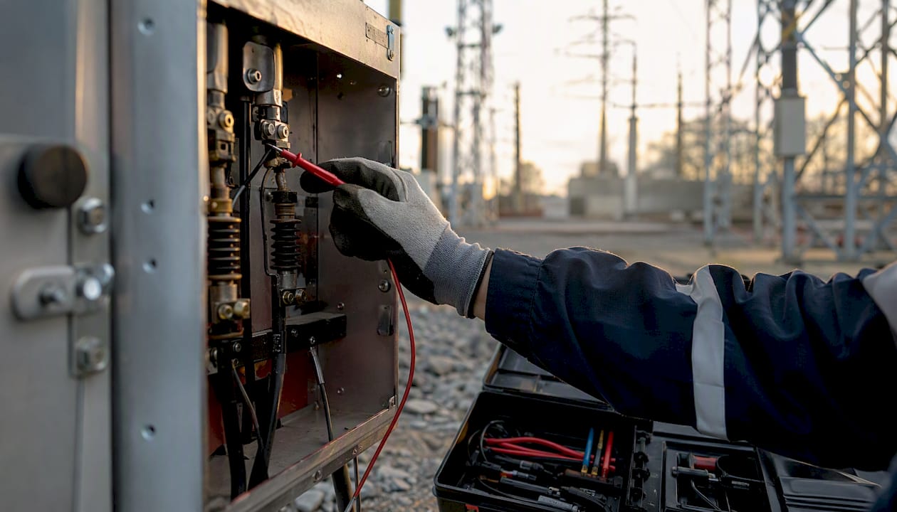
Site selection combines technical due diligence with commercial and political factors. ICF’s data center practice identifies securing utility access and community buy-in as the single largest schedule risk on U.S. projects — a technically sound site with an uncooperative utility or an organized community opposition group can stall a project for years.
| Risk category | Key criteria | Weight (high/medium/low) | Mitigation |
|---|---|---|---|
| Power access | Available capacity, interconnection queue, rate structure, dual-feed feasibility | High | Engage utility pre-application; assess substation headroom |
| Fiber connectivity | Route diversity, latency to major IXPs, carrier options | High | Confirm at least two diverse fiber entry points |
| Water access | Municipal supply capacity, discharge permits, drought risk | Medium–High | Evaluate water-free cooling alternatives early |
| Geotechnical | Bearing capacity, seismic zone, flood plain, soil contamination | Medium | Commission Phase I/II ESA and geotech report |
| Permitting complexity | Zoning, AHJ review cycles, environmental review triggers | High | Pre-application meeting with AHJ before site commitment |
| Community acceptance | Proximity to residential areas, ESG visibility, local employment impact | High | Stakeholder mapping and ESG disclosure strategy |
Power and fiber are the two non-negotiable hard criteria. A site without a credible path to the required utility capacity within the project timeline should be eliminated from the shortlist regardless of other advantages. Fiber route diversity — at minimum two physically separate entry points from different carriers — is equally non-negotiable for any facility targeting Tier III or above.
Water is an increasingly scrutinized resource. Evaporative cooling towers consume significant volumes, and several U.S. municipalities have imposed restrictions or denied permits on that basis alone. Evaluating water-free or water-reduced cooling alternatives (air-side economizers, direct liquid cooling) during site feasibility avoids a late-stage redesign.
Community opposition is a growing and material risk across U.S. markets. Energy usage, water consumption, and land-use impacts are the three most common objections. Projects that treat community engagement as a permitting formality rather than a genuine stakeholder process routinely encounter organized opposition that extends permitting timelines by 12–24 months.
Pro Tip: Conduct a stakeholder mapping exercise before signing a site option agreement. Identify local elected officials, utility contacts, environmental advocacy groups, and neighboring landowners. A pre-application community briefing — before formal permit submission — consistently reduces opposition intensity and shortens review cycles.
Professional engineers who understand compliance requirements can accelerate the permitting process by preparing submissions that anticipate AHJ concerns and align with local zoning and environmental standards from the outset.
What power architecture and redundancy strategy should you use?
The electrical power chain in a data center runs from the utility service entrance through medium-voltage switchgear, transformers, UPS systems, static transfer switches (STS), automatic transfer switches (ATS), generators, and power distribution units (PDUs) to the IT equipment. Each component in that chain is a potential single point of failure, and the redundancy strategy determines how many of those failures the facility can absorb without affecting load.
Redundancy options compared:
| Redundancy model | Availability profile | Capex multiplier | Operational complexity | Best fit |
|---|---|---|---|---|
| N (no redundancy) | Single path; any failure affects load | 1.0x | Low | Development/test environments |
| N+1 | One spare per system; concurrent maintenance possible | about 1.5x | Medium | Tier III enterprise, colocation |
| 2N (fully redundant) | Dual independent paths; fault-tolerant | approximately 2x | High | Tier IV, financial services, critical national infrastructure |
| 2N+1 | Dual paths plus one additional spare | around 2x | Very high | Highest-criticality government or defense |
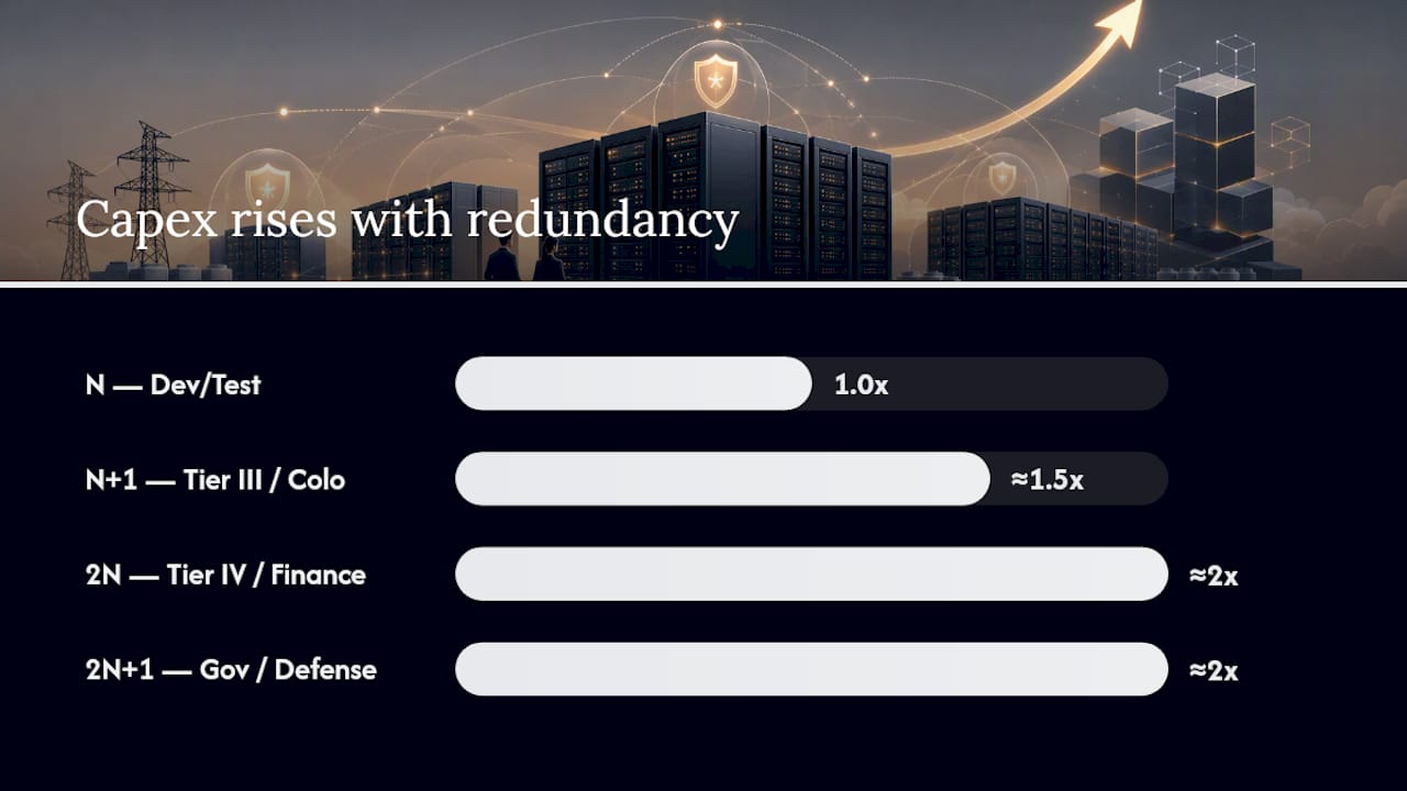
The Uptime Institute Tier framework maps directly to these redundancy levels: Tier I and II are N or partial-N configurations; Tier III requires N+1 with concurrent maintainability; Tier IV requires 2N fault tolerance. Applying the Tier methodology early — during schematic design — clarifies trade-offs between availability, capital cost, and operational staffing requirements before procurement specifications are issued.
Practical decision rules:
- Match redundancy to the financial impact of downtime, not to a generic “best practice.” A development environment does not require 2N UPS.
- Dual utility feeds from separate substations materially reduce the risk of extended outages and should be pursued wherever the local utility can accommodate them.
- Generator fuel logistics — tank sizing, fuel delivery contracts, and load test schedules — are frequently underspecified. A Tier III facility with 12-hour on-site fuel storage and no confirmed delivery contract is operationally Tier I during an extended grid outage.
- On-site generation (natural gas, diesel, or emerging hydrogen fuel cell systems) combined with battery energy storage systems (BESS) can reduce dependence on grid stability and support sustainability targets simultaneously.
Single-line diagram review by a licensed electrical engineer is a mandatory deliverable before construction documents are issued. The single-line must reflect the as-designed redundancy architecture, not a generic template.
How should you approach cooling and thermal management?
Cooling represents the second-largest energy consumer in most data centers after IT load itself, and the thermal management strategy chosen at schematic design determines both the facility’s PUE and its ability to accommodate future density increases.
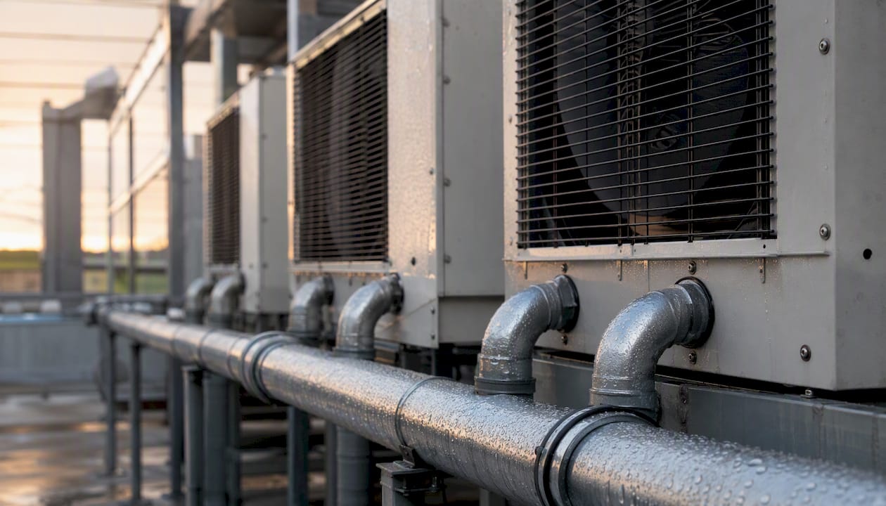
Primary cooling architectures range from traditional computer room air conditioning (CRAC) and computer room air handlers (CRAH) with hot/cold aisle containment, through rear-door heat exchangers, to direct-to-chip liquid cooling and full immersion cooling. Each serves a different rack density range.
ASHRAE’s thermal guidelines — specifically the ASHRAE TC 9.9 allowable and recommended envelope — define safe inlet temperature and humidity ranges for IT equipment. Widening setpoints to the upper end of the ASHRAE A2 envelope (up to 95°F / 35°C inlet) allows greater use of free cooling hours in most U.S. climates, directly reducing mechanical plant runtime and improving PUE.
Air-based cooling with hot/cold aisle containment remains cost-effective and maintainable for rack densities up to approximately 15–20 kW per rack. Above that threshold, the volume of conditioned air required becomes physically impractical, and liquid cooling becomes the technically superior choice. For AI training clusters operating at 40–100+ kW per rack, direct-to-chip or immersion cooling is not a future option — it is the only architecture that can remove heat at the required rate without a prohibitive mechanical footprint.
Designing cooling capacity with headroom for future density increases is one of the highest-return investments in a data center program. A facility sized only for smaller initial rack densities that later must support much higher densities will require a full mechanical retrofit, resulting in significant additional costs.
Pro Tip: Specify cooling infrastructure in zones, not as a single facility-wide system. Zoned cooling allows high-density AI or GPU clusters to be served by liquid cooling while standard compute rows continue on air-based systems — avoiding a full facility retrofit when density requirements change.
For carbon footprint reduction in construction projects, passive and free-cooling strategies — air-side economizers, evaporative pre-cooling, and heat recovery — provide measurable efficiency gains that compound over a facility’s operational life.
How do you measure and improve data center energy efficiency?
PUE — Power Usage Effectiveness — remains the primary efficiency metric for data centers. It is calculated as total facility power divided by IT equipment power. A PUE of 1.0 is theoretical perfection; a PUE of 2.0 means the facility consumes as much energy on overhead (cooling, lighting, power conversion losses) as on IT load.
| Metric | Definition | Enterprise target | Colocation target | Hyperscale target |
|---|---|---|---|---|
| PUE | Total facility power / IT power | ≤2.0 | ≤2.0 | ≤2.0 |
| WUE (Water Usage Effectiveness) | Annual water use / IT energy consumed | <1.0 L/kWh | <1.0 L/kWh | <1.0 L/kWh |
| CUE (Carbon Usage Effectiveness) | CO₂ equivalent / IT energy consumed | Varies by grid mix | Varies by grid mix | Target near zero with renewables |
| ERE (Energy Reuse Effectiveness) | (Total energy – reused energy) / IT energy | N/A for most | N/A for most | <1.0 where waste heat recovery applies |
PUE alone does not capture carbon intensity or water use, which are increasingly scrutinized by regulators, investors, and communities.
Practical efficiency measures:
- Air-side and water-side economizers: free cooling hours in most U.S. climates can supply 30–70% of annual cooling demand without mechanical refrigeration.
- On-site renewables (rooftop photovoltaic, power purchase agreements): PPAs are the most common mechanism for large U.S. data centers to achieve renewable energy targets without on-site generation constraints.
- Demand-side management and load shifting: scheduling non-time-sensitive batch workloads during periods of low grid carbon intensity reduces CUE without capital investment.
- Waste heat recovery: large facilities in urban or industrial settings can export waste heat to district heating networks, improving ERE and creating a revenue or offset opportunity.
USGBC’s LEED certification pathway for data centers provides a structured framework for documenting energy and water efficiency performance, setting measurable targets during design, and demonstrating sustainability commitments to regulators, investors, and communities. LEED certification is increasingly referenced in permitting discussions and corporate ESG disclosures.
When do modular and prefabricated approaches make sense?
Modular and prefabricated data center construction compresses time-to-capacity by moving fabrication off the critical path.
Because data centers are designed for 15–20 year lifespans, while AI-driven density requirements evolve far faster, modular architectures that allow incremental capacity additions without full-facility shutdowns are particularly valuable for organizations with uncertain growth trajectories.
Use cases where modular approaches are most appropriate:
- Rapid capacity deployment: When time-to-market is the primary constraint and a 12–18 month traditional build is not acceptable.
- Phased investment: When capital must be deployed incrementally rather than committed upfront for full-facility build-out.
- Remote or constrained sites: Where site access, labor availability, or logistics make traditional construction impractical.
- Edge deployments: Containerized edge nodes can be deployed, relocated, and decommissioned far more efficiently than permanent structures.
- AI inference scaling: Pod-based high-density modules can be added to an existing facility to serve GPU clusters without retrofitting the main data hall.
Risk considerations for modular delivery:
- Factory-to-site integration testing must be specified contractually. Modules that test correctly in isolation can fail when integrated with site MEP systems if interface specifications are not rigorously defined.
- Mechanical and electrical tolerance management between prefabricated modules and site-built infrastructure requires detailed coordination drawings — BIM models are the most reliable mechanism for detecting clashes before installation.
- Lead times for prefabricated modules from major manufacturers typically range from several to many weeks depending on configuration and order volume.
Traditional facility builds remain the appropriate choice for large-scale, long-term campuses where total cost of ownership over 20+ years outweighs the speed advantage of modular delivery.
What security, fire safety, and compliance standards apply?
Data center compliance spans physical security, cybersecurity, fire safety, and sustainability — each governed by a distinct set of standards and authorities. The following standards are mandatory references for U.S. projects:
- Uptime Institute Tier Standard: Defines availability, redundancy, and concurrent maintainability requirements for Tier I through IV. Tier certification requires both design documentation review and operational verification.
- ASHRAE TC 9.9: Sets allowable and recommended temperature and humidity envelopes for IT equipment. Design teams must specify CRAC/CRAH setpoints and containment configurations that keep IT inlet conditions within the applicable ASHRAE class.
- NIST Cybersecurity Framework (CSF): The primary U.S. federal reference for information security risk management. Physical design decisions — access control zoning, cable management, network segmentation — must align with NIST CSF controls. CISA’s federal information security guidance provides additional requirements for facilities handling federal data.
- ISO/IEC 27001: The international standard for information security management systems. ISO’s data center sector guidance covers management system requirements that complement physical design decisions.
- USGBC LEED: Provides the sustainability certification framework referenced in permitting, ESG disclosures, and procurement specifications.
Fire safety in data centers involves suppression system selection (clean agent, pre-action sprinkler, or hybrid), early warning detection (VESDA systems), and compartmentalization. The AHJ interprets NFPA 75 (Standard for the Fire Protection of Information Technology Equipment) and NFPA 76 (Telecommunications Facilities) for most U.S. data center projects. Suppression system selection must be coordinated with the IT equipment manufacturer’s requirements — some equipment warranties are voided by water-based suppression.
Security zoning follows a concentric model: perimeter security (fencing, vehicle barriers, CCTV), building access control (mantraps, biometric authentication), data hall access (per-row or per-cage access control), and equipment-level security (locked cabinets, asset tracking). Each zone boundary must be defined in the design documents and verified during commissioning.
The Tier target chosen at schematic design is not merely an availability specification — it determines mechanical redundancy, footprint, staffing model, and commissioning scope. A project that selects Tier III but designs to Tier II standards will fail certification and require costly remediation. Confirm the Tier target in writing before detailed design begins.
Pro Tip: Request a pre-design meeting with the AHJ before issuing construction documents. AHJs in many U.S. jurisdictions have developed specific interpretations of NFPA 75 and local fire codes for data centers. Discovering those interpretations after permit submission adds weeks to the review cycle.
How do you operate, monitor, and commission a data center?
Commissioning is the process that validates the as-built facility against the design intent before IT load is introduced. It is not a final inspection — it is a structured testing program that begins during construction and concludes with an integrated systems test (IST) under simulated load conditions.
Commissioning sequence:
- Level 1 (factory acceptance testing): Major equipment tested at the manufacturer’s facility before shipment.
- Level 2 (startup and verification): Individual systems started and verified against specifications after installation.
- Level 3 (functional testing): Each system tested through its full operational range, including failure modes.
- Level 4 (integrated systems testing): All systems tested together under simulated load, including UPS transfer, generator start and transfer, and BMS alarm response.
- Level 5 (operational acceptance): Facility operated under actual or simulated IT load for a defined period to verify steady-state performance.
Data Center Infrastructure Management (DCIM) platforms integrate real-time monitoring of power, cooling, space, and environmental conditions with capacity planning and asset management. Modern DCIM systems increasingly incorporate AIOps capabilities — anomaly detection, predictive maintenance alerts, and automated capacity recommendations — that reduce the operational burden on facilities staff.
Operational checklist items:
- UPS and generator transfer tests: verify automatic transfer within specified time limits under full load.
- Load bank testing: confirm generator capacity at 100% nameplate rating for a minimum of 4 hours.
- BMS integration verification: confirm all alarm points, setpoint adjustments, and escalation paths are functional.
- Spare-parts strategy: critical spare parts (UPS modules, PDU breakers, cooling coils) must be on-site or under a guaranteed delivery contract before operations commence.
- Maintenance scheduling: preventive maintenance intervals for all major equipment must be documented and resourced before handover.
Staffing models range from fully owner-operated to fully outsourced facilities management. The decision depends on the organization’s internal technical capability, the criticality of the facility, and the cost of building and retaining specialized staff. Third-party facilities management is appropriate when the organization lacks the internal depth to maintain Tier III or IV systems reliably.
What do data center projects typically cost and how long do they take?
Timeline and budget vary significantly by facility type, size, location, and redundancy target. The figures below represent typical ranges for U.S. enterprise and colocation builds in the 1–20 MW IT load range.
| Budget driver category | Typical share of total project cost | Key variables |
|---|---|---|
| Site acquisition and preparation | 5–15% | Land cost, geotechnical conditions, utility extension distance |
| Building shell and structure | around 15–20% | Construction type, seismic zone, floor loading requirements |
| Electrical infrastructure (UPS, generators, switchgear, PDUs) | about 25% | Redundancy level, generator fuel type, transformer procurement |
| Mechanical and cooling systems | 20–30% | Cooling architecture, economizer type, cooling tower vs. chiller |
| IT fit-out (racks, cabling, network) | about 5% | Density, structured cabling standard, network redundancy |
| Commissioning and testing | 2–5% | Tier target, third-party commissioning agent scope |
| Soft costs (design, permitting, project management) | 8–15% | Jurisdiction complexity, design iterations, permitting duration |
Typical timeline ranges:
- Feasibility to schematic design usually spans several months
- Permitting periods vary widely, often spanning months to over a year
- Construction typically takes from one to multiple years
- Commissioning generally lasts from a few weeks to several months
- Total feasibility to operations may range from about a year to several years depending on build type
Developer/owner models and build-to-suit arrangements transfer construction risk to a specialist developer in exchange for a long-term lease commitment. Value engineering applied during schematic and detailed design phases consistently identifies 5–15% cost reduction opportunities without compromising performance or compliance.
The highest-ROI investments are typically in redundancy architecture (which directly reduces downtime risk) and cooling headroom (which avoids costly retrofits as density increases).
What are the most common data center project mistakes?
Pitfall 1: Misalignment between infrastructure design and business goals. Deloitte identifies this as the most common failure mode, recommending that energy strategy, capital models, and operational frameworks be integrated from pre-planning. The mitigation is a written design brief — signed by both business and technical leadership — before schematic design begins.
Pitfall 2: Late utility and fiber procurement. Utility interconnection queues in U.S. markets have extended materially. Treating power access as a construction-phase activity rather than a pre-feasibility task adds 12–24 months to the program. Mitigation: submit utility pre-application and fiber route confirmation before site option agreements are signed.
Pitfall 3: Underestimating community and permitting risk. Public opposition over energy use, water consumption, and land impact is reshaping permitting timelines across U.S. markets. Projects that skip early community engagement routinely encounter organized opposition that extends review cycles. Mitigation: conduct stakeholder mapping and initiate community briefings before formal permit submission.
Pitfall 4: Under-provisioned cooling for future density. Facilities designed to current average rack densities without headroom for AI workloads face full mechanical retrofits within 5–7 years. Mitigation: specify cooling infrastructure in zones with structural and MEP provisions for future liquid cooling installation.
Pitfall 5: Inadequate commissioning scope. Commissioning scoped as a final inspection rather than a structured testing program consistently produces facilities that fail under real operational conditions. Mitigation: engage a third-party commissioning agent at schematic design, not after construction is complete.
Speed-to-market must be paired with evidence-based design. Rushing site selection without aligning energy and permitting strategy increases risk rather than reduces it — a lesson that applies equally to first-time developers and experienced operators entering a new market.
Pro Tip: Apply a “pre-mortem” exercise at the end of schematic design: ask the full project team to identify the three most likely causes of failure. This structured exercise surfaces assumptions that have not been validated and creates accountability for resolving them before detailed design begins.
Planning-phase checklist to avoid these pitfalls:
- Written design brief with capacity, availability, and sustainability targets signed by business and technical leadership
- Utility pre-application submitted and interconnection feasibility confirmed
- Fiber route diversity confirmed with at least two carriers
- Stakeholder mapping completed and community briefing scheduled
- Cooling zoning strategy documented with provisions for future density
- Third-party commissioning agent engaged
How do you select the right data center design consultancy?
The quality of the engineering and design consultancy engaged for a data center project is a primary determinant of delivery risk. The following evaluation framework applies to both initial selection and ongoing performance management.
Prioritized selection criteria:
- Demonstrated Tier experience: Request references for completed projects at the target Tier level. Ask specifically about Tier III or IV certification outcomes — not just design intent, but actual certification results.
- Delivery model track record: Confirm the firm has completed projects in the relevant delivery model — modular, hyperscale, colocation, or enterprise. Each model has distinct design, procurement, and commissioning requirements.
- Local permitting experience: Data center permitting in the U.S. is jurisdiction-specific. A firm with established relationships with the relevant AHJ and utility reduces permitting risk materially.
- Commissioning references: Ask for references from commissioning agents who have worked with the firm. A design team that has never been through a Tier IV IST will not produce commissioning-ready documentation.
- BIM and digital engineering capability: BIM modeling services reduce coordination errors, accelerate permitting, and support lifecycle decisions. Confirm the firm’s BIM execution plan and software standards.
- ESG and sustainability track record: Confirm experience with LEED submissions, ASHRAE compliance documentation, and utility incentive program applications.
Interview questions for technical, program, and commercial evaluation:
- Describe the commissioning protocol you use for a Tier III facility. Who is the commissioning agent and at what phase are they engaged?
- How do you manage the interface between prefabricated modules and site-built MEP systems?
- What is your process for utility pre-application and AHJ pre-submission meetings?
- How do you structure your BIM coordination process between structural, MEP, and architectural disciplines?
- Provide two references from data center projects where you managed a permitting challenge or community opposition issue.
Red flags to watch for:
- No commissioning references or a commissioning process described as a post-construction activity
- Inability to provide Tier certification outcomes (not just design intent) for completed projects
- No evidence of utility or community engagement experience
- Weak or absent ESG track record on comparable projects
- Generic design templates presented as project-specific solutions
For organizations requiring a structured discovery engagement to de-risk early phases, a feasibility study scoped to validate site, power, fiber, and permitting assumptions before capital commitment is the appropriate first engagement. This produces a documented basis for the business case and design brief without committing to full design fees.
The methodology and standards Com follows on data center projects
Com’s approach to data center projects is grounded in evidence-based design, integrated energy strategy, BIM and digital engineering, and staged commissioning — applied within the standards frameworks that govern U.S. data center design and construction.
| Methodology element | Standards and tools applied | Outcome delivered |
|---|---|---|
| Evidence-based design | Uptime Institute Tier Standard, ASHRAE TC 9.9 | Availability and thermal performance aligned to business SLOs |
| Integrated energy strategy | USGBC LEED, DOE efficiency benchmarks | PUE and carbon targets set and documented at schematic design |
| BIM and digital engineering | Autodesk Revit, Navisworks coordination | Clash detection, permitting acceleration, lifecycle model |
| Staged commissioning | NFPA 75/76, Uptime Institute commissioning protocols | IST-verified performance before IT load introduction |
| Information security design | NIST CSF, ISO/IEC 27001 | Security zoning and access control aligned to risk framework |
| Statutory submissions | AHJ, local building code, utility interconnection | Permit-ready documentation from first submission |
Commissioning protocol overview: Com engages third-party commissioning agents at schematic design — not post-construction — to ensure that design documentation is commissioning-ready before construction begins. Acceptance tests are scoped against the Tier target and include load bank testing, UPS and generator transfer verification, BMS integration testing, and a full IST under simulated load.
BIM and digital engineering reduce coordination errors between structural, MEP, and architectural disciplines by detecting clashes in the model before they become field conflicts. BIM models also accelerate permitting by providing AHJs with three-dimensional documentation that is faster to review than traditional two-dimensional drawings, and they support lifecycle decisions by maintaining an accurate as-built record throughout the facility’s operational life.
Proof points for Com’s data center practice — including project case studies, author credentials, and client references — are available upon request. Decision-makers are encouraged to request a portfolio review as part of the consultancy selection process.
What practitioners get wrong about data centers design priorities
The conventional wisdom in data center planning places redundancy architecture at the center of every design decision. That instinct is understandable — downtime is visible, quantifiable, and career-limiting. But the projects that deliver the best long-term outcomes consistently share a different priority order: they get the energy strategy right first, then design redundancy to match it.
The reason is structural. A facility’s energy procurement model — whether it relies on grid power, on-site generation, PPAs, or a hybrid — determines the capital structure, the sustainability profile, and the operational cost base for the next 20 years. Redundancy architecture, by contrast, can be adjusted within a defined range during detailed design without fundamental rethinking. Reversing that sequence — committing to a 2N electrical architecture before the energy strategy is resolved — produces facilities that are highly available but commercially uncompetitive, because the capital and operating cost of full redundancy was not weighed against the actual financial impact of downtime for that specific workload.
The second underappreciated priority is community and permitting risk. Most technical teams treat permitting as an administrative step that follows design. In the current U.S. environment, permitting is a design constraint. The communities adjacent to proposed data center sites are better organized, better informed, and more politically effective than they were five years ago. A project that does not engage those communities before permit submission is not saving time — it is accumulating risk that will surface at the worst possible moment.
The practical implication: the first two months of any data center program should be spent on energy strategy, stakeholder mapping, and utility pre-application — not on architectural concepts or equipment specifications. The design follows from those decisions; it does not precede them.
Com’s engineering services for U.S. data center projects
Data center projects require an engineering partner who can move from site feasibility through statutory submissions, MEP design, and commissioning support without losing continuity across phases. Com delivers exactly that scope — civil and structural design services calibrated to the heavy floor loadings, seismic requirements, and utility interface conditions that data center facilities demand, combined with MEP coordination, BIM execution, and commissioning oversight.
The most common engagement types for data center clients are: a pre-feasibility study that validates site, power, fiber, and permitting assumptions before capital commitment; design-build support that carries the project from schematic design through construction documents and AHJ submissions; and commissioning oversight that provides independent verification of IST results against the Tier target. Each engagement is scoped to deliver a defined, documented output — not an open-ended retainer.
For decision-makers ready to begin, the immediate next step is a structured discovery session to align the business case, confirm site shortlist criteria, and scope the feasibility study. Contact Com to schedule that session and receive a fixed-scope proposal within five business days.
Sources
The following primary sources and standards should be distributed to technical leads and referenced throughout the design and construction lifecycle.
- Data Center Solutions | Deloitte US
- Data Centers Solutions and Consulting | ICF
- Uptime Institute Professional Services | Data Center – Uptime Institute
- How to future-proof your data center design – DCD
- LEED data center certification | USGBC
Share this reference list with your engineering leads and commissioning team at project kickoff.