
Shop Drawing Production for Formwork Systems: Why PE Review Saves Time on Site
Introduction
Shop drawing production for formwork systems determines whether a concrete pour proceeds on schedule or stalls for days. A Professional Engineer (PE) review of these shop drawings catches structural, constructability, and safety issues on paper, so contractors spend less time troubleshooting at the construction site. On Singapore and ASEAN infrastructure projects (bridges, viaducts, MRT stations, water treatment plants), where programmes run on tight multi-shift cycles, that difference compounds across dozens of pours.
This article focuses on temporary works and formwork systems for walls, slabs, beams, columns, and bridge decks. It does not cover permanent structural design or generic scaffolding. The target readers are main contractors, formwork subcontractors, temporary works coordinators, and any project manager working under Singapore’s BCA, LTA, or MOM safety regulations who needs to understand how PE-reviewed formwork drawings translate into fewer site delays.
By the end, you will:
- Understand what “good” formwork shop drawings must include and how they differ from design drawings.
- See how PE review changes those drawings and why that saves days or weeks on site.
- Learn a step-by-step workflow for efficient formwork shop drawing production.
- Recognise common formwork mistakes and how PE review prevents them.
- Know when to engage AMAN Engineering Consultancy Pte Ltd for formwork and temporary works support.
Understanding Formwork Shop Drawing Production
Formwork is temporary, but the consequences of getting it wrong are permanent. Shop drawings provide detailed construction instructions for specific components; for formwork, that means specifying exactly how panels, props, walers, ties, and bracing come together to support fresh concrete until it reaches design strength. Poor formwork drawings lead to cancelled pours, material waste, and schedule slippage on infrastructure projects where every shift counts.
Formwork must resist heavy loads from wet concrete, equipment, and construction staff. Because these loads are transient and change with pour rate, temperature, and vibration method, the detail required in formwork shop drawings goes beyond what a standard structural plan covers.
What Are Formwork Shop Drawings?
Formwork shop drawings are contractor-produced, extremely detailed drawings showing how wall, slab, beam, column, pier, and soffit formwork will be assembled, supported, and stripped. They are typically prepared by contractors or subcontractors, not architects. They include dimensions, materials, and assembly methods for accuracy, and they must be reviewed by architects engineers and the design team for accuracy, then approved before fabrication starts so the approval process helps prevent errors on-site.
Key information in a formwork shop drawing package includes construction details and fabrication details for the temporary works system:
- Panel layouts, support spacing, and tie locations. Waler and soldier arrangement, proprietary system references (PERI, Doka, RMD, Meva where applicable), and connection details between adjacent panels.
- Loads and design assumptions. Fresh concrete lateral pressure calculations (based on pour rate, concrete temperature, and vibration type), construction loads, and wind loads, validated or prepared by a PE.
- Connections to permanent works. Anchorage to existing concrete structures, bearing on slabs or ground, and load transfer to shoring towers.
- Stripping sequences and re-shoring arrangements. PE-reviewed formwork drawings clarify concrete stripping timelines and procedures, preventing premature removal that could overload lower floors.
The distinction from permanent structural design drawings is straightforward: design drawings focus on overall building aesthetics and layout, showing RC member sizes and reinforcement bars. Formwork shop drawings show the temporary system that safely holds those members during casting. As-built drawings, by contrast, show the actual construction after project completion.
Typical Workflow for Producing Formwork Shop Drawings
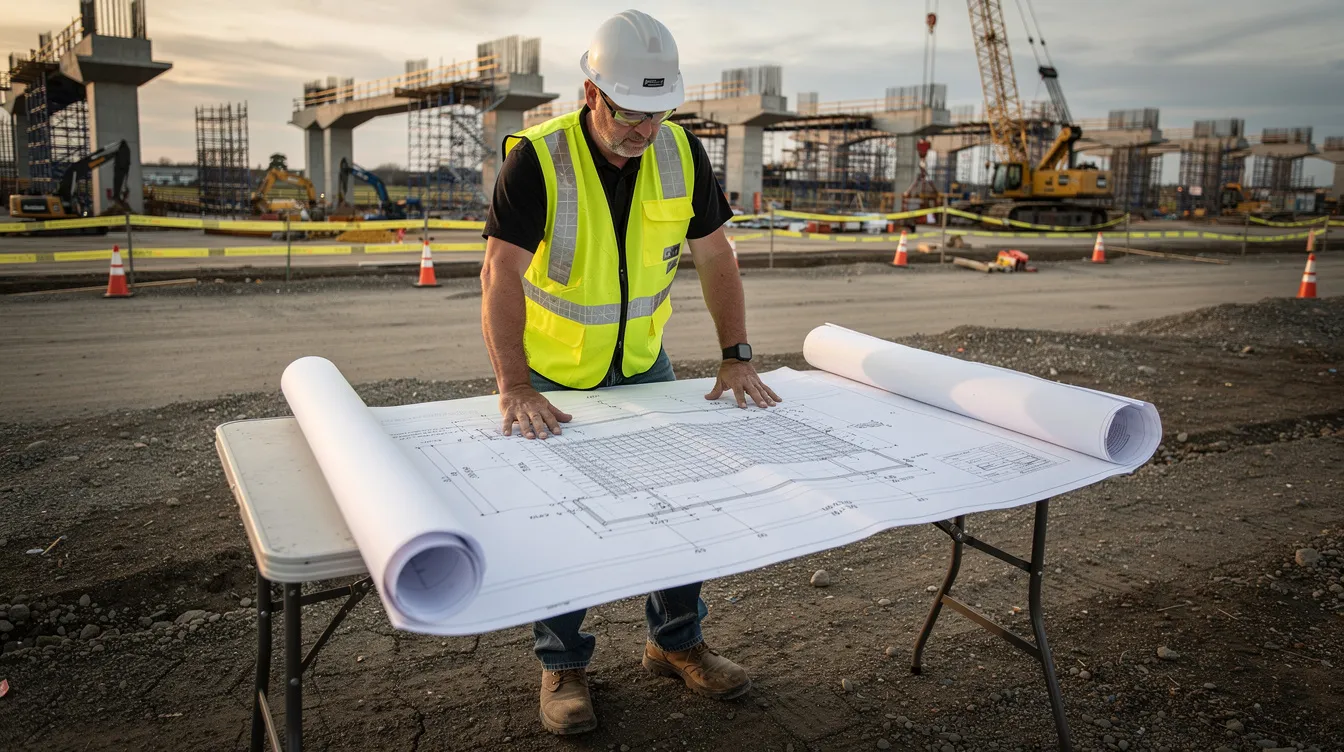
Contractors begin by extracting geometry from the latest IFC or BIM model. On infrastructure works, this means capturing curved viaduct alignments, varying pier heights, crossfalls, and thick transfer beam dimensions. Inaccurate or late permanent-works models create downstream errors in every formwork drawing produced from them.
With geometry in hand, the construction team selects available formwork systems and accessories from supplier catalogues, matching panel sizes and prop capacities to the structural requirements. Preliminary 2D layouts, sections, and assembly details are then prepared in AutoCAD, Revit, or Tekla Structures. The aim is to create shop drawings that provide clear instructions for specific components, including dimensions, materials, and assembly methods.
The drawings are submitted to a PE for review and endorsement where required by contract, BCA, LTA specifications, or WSH (Construction) Regulations 2007 Part IX. Skipping this step leads to one of two outcomes: conservative, over-designed systems that consume too many props and slow down assembly, or under-designed systems that fail inspections and trigger stop-work orders. Clearer documentation also improves project coordination across teams and facilitates faster project work on site.
To understand where PE review adds the most value, it helps to examine the specific risks formwork systems carry.
Risks and Constraints Specific to Formwork Systems
Formwork drawings must address several categories of risk:
Structural safety. Collapse from hydrostatic concrete pressure, vibration, construction loads, or wind is the primary hazard. For a wall pour, fresh concrete lateral pressure can reach approximately 38 kPa at certain depths and pour rates; underestimating this pressure leads to blown ties or bulging panels. Under MOM’s advisory for PEs on formwork safety, formwork structures must sustain all loads with a minimum safety factor of 2.
Geometric control. Deflection and settlement limits directly affect final line and level for bridge decks, viaduct segments, and MRT station slabs. A 5 mm overbend becomes a 5 mm correction later.
Site logistics. Infrastructure sites impose constraints that building projects rarely face: live traffic corridors with night-only work windows, tunnelling shafts with limited crane reach, and brownfield industrial sites with existing utilities below grade.
Regulatory compliance. Singapore’s WSH (Construction) Regulations mandate PE design for formwork exceeding 9 m height, formwork supported on two or more tiers of shores, and slab/beam formwork thicker than 300 mm. LTA specifications add that any wall formwork 4 m or taller requires PE design and a Certificate of Supervision before casting.
Interfaces with other trades. Conflicts with reinforcement congestion, embedded items, M&E openings, pipe routes, and construction joints cause last-minute modifications. Each clash that reaches the construction site instead of being resolved on paper adds hours or days to the programme.
PE review is designed to manage all five risk categories systematically, which is why it produces a measurable schedule benefit on site.
Why PE Review of Formwork Shop Drawings Saves Time on Site
Every clash removed on a drawing is one fewer RFI and one fewer stoppage on site. PE review functions as both an engineering check and a workflow optimisation tool; it validates structural adequacy while simultaneously forcing the kind of coordination that prevents rework during the construction phase.
Early Detection of Structural and Stability Issues
A PE checks global stability (overall frame behaviour, bracing adequacy, foundation bearing capacity) and local elements (panel capacities, prop buckling loads, tie forces, anchor pull-out resistance). Formwork safety checks include verifying bracing, support conditions, and load transfer. PE reviews verify load-bearing calculations for dead loads and live loads in formwork, ensuring that each component in the system can carry what is demanded of it.
Without PE review, failures or near-misses trigger work stoppages, incident investigations, and redesign. In 2018, a skin-wall formwork failure at the Great World MRT station’s Entrance B led LTA to ban the responsible PE who had under-designed a key component of the temporary work installation. In August 2016, 24 table formworks collapsed on a building project in Singapore; deficiencies in bracing and anchorage for wind loads were identified as contributing factors.
With PE review, realistic load paths and bracing configurations are confirmed before mobilisation. A PE-endorsed drawing provides accountability and ensures proper construction practices. The time saved is not incremental; it is the difference between proceeding with a pour and shutting down a workfront for investigation.
Improved Buildability and Access Planning
PE-led review practically optimises several aspects that contractors often resolve reactively on site by helping components fit together correctly on-site and improving coordination among architects, engineers, and contractors.
Access ways for workers, rebar installation, and concrete placement are verified against the formwork layout. Once wall or soffit formwork is erected, reconfiguring access is slow and expensive. A PE review facilitates smoother site execution by addressing impractical installation sequences before panels are lifted into place, so teams can install parts correctly and avoid delays and costly rework through early identification of design discrepancies before materials reach the site.
Crane and lifting plans for heavy formwork tables or traveller systems on bridge projects are checked against available crane capacity and reach. On a viaduct project with night-only lifting windows, a table form that is 200 kg over the crane’s rated capacity at the required radius stops work entirely.
Pour sequencing is coordinated with prop relocation and re-shoring cycles. On multi-span decks, the order of striking, re-shoring, and new prop installation determines how many formwork sets the contractor needs. Clear sequencing from PE review means fewer ad-hoc modifications and smoother interface with rebar and M&E trades.
Reduced RFIs, Rework, Quality Control, and Inspection Failures
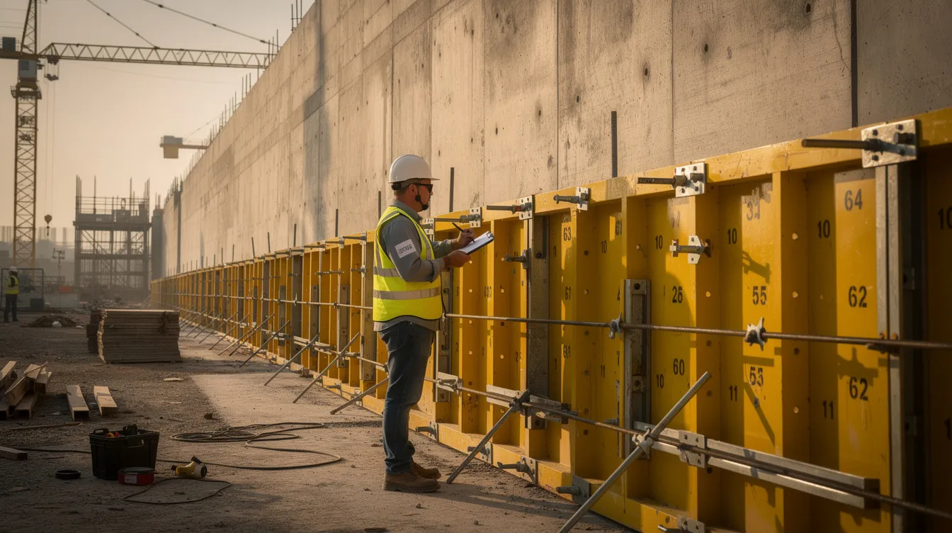
PE review systematically reduces three categories of delay because precise, approved drawings reduce construction errors and strengthen quality control against project specifications:
RFIs during pre-pour inspections. When the Resident Engineer, RTO, or client’s consultant finds missing information or non-compliant details in reviewing shop drawings, they issue an RFI. Each RFI triggers a response cycle; on LTA and JTC infrastructure works, even one cancelled pour can push the schedule by two to three days once remobilisation, re-inspection, and crew rescheduling are factored in. PE reviews catch design errors and coordination gaps before materials reach the site.
Failed safety audits. Regulatory compliance during construction often requires documented engineering oversight. Effective PE reviews create a document trail for safety audits and compliance checks. Without that trail, MOM inspectors or client safety teams can issue non-conformance reports that halt work until documentation is completed.
Rework from coordination gaps. Wrongly placed ties, insufficient headroom for rebar cages, or blocked embedded items all require on-site correction. Shop drawings reduce fabrication rework by 40% when properly coordinated and reviewed. Early identification of design discrepancies helps avoid delays and costly rework, while accurate shop drawings help avoid costly construction delays and help control construction costs by reducing corrective work.
Optimised Material Usage and Panel Reuse Cycles
PE input reduces over-propping and over-bracing that consume excessive props and frames, limiting parallel workfronts. It also eliminates non-standard panel cuts that are slow to assemble and difficult to reuse on subsequent pours.
Properly engineered layouts allow quicker turnaround of formwork sets along a viaduct or retaining wall. If a PE rationalises a four-span viaduct layout so that the same table form configuration works on every span, the contractor avoids fabricating bespoke fillers for each span. Fewer sets of expensive proprietary systems are needed when cycle times are shorter and more predictable. Clear and coordinated drawings support planning for materials and resources efficiently, and clear shop drawings help control construction costs by identifying issues early rather than correcting them in the field.
Implementing an Efficient PE-Reviewed Formwork Shop Drawing Process
The full benefit of PE review is realised only when it is integrated early into the contractor’s production workflow. Engaging a PE after formwork components have been ordered and delivered limits the PE’s ability to optimise layouts or catch fundamental system selection errors. This section describes a practical, repeatable process that AMAN Engineering Consultancy commonly uses with civil infrastructure clients.
Step-by-Step Workflow from Concept to Approval Process and Approved Drawings
- Define pour sequence and construction constraints. The contractor identifies traffic management plans, night work windows, crane locations, and access limits. This information shapes every downstream decision.
- Extract geometry from latest IFC drawings and/or BIM model. Levels, cambers, crossfalls for roads and viaducts, and exact dimensions of structural members are captured. Late or incorrect models cause errors in every subsequent drawing.
- Develop preliminary formwork scheme. System selection (table forms, climbing systems, conventional panel-and-prop) is matched to the project’s geometry, pour sequence, and budget. Standard solutions are preferred over project-specific fabrications.
- Produce detailed layouts and sections. Panel arrangement, prop spacing, bracing layout, working platforms, access ladders, installation details, and joint details are drawn. This step is where shop drawing services add the most drafting value.
- PE review and structural checks. Load calculations, member verification, anchor capacities, foundation checks, and fresh concrete pressure profiles are completed. The PE confirms compliance with SS 580:2020 and WSH Regulations.
- Coordination with other trades and safety teams. Clash detection with rebar, M&E, temporary traffic diversions, and embedded items is completed. This step often overlaps with Step 5.
- Final amendments, stamping/endorsement, and controlled issue to site teams. The approved shop drawings are revision-controlled and distributed. Any on-site change requires re-endorsement.
AMAN Engineering typically leads Steps 4 through 7. The contractor leads Steps 1 through 3, providing the site constraints and system preferences that inform the engineering.
Roles and Responsibilities: Contractor, Formwork Supplier, and PE
| Responsibility | Contractor | Formwork Supplier | PE Consultant |
|---|---|---|---|
| Site data and constraints (schedule, equipment, access) | Provides | Receives | Receives |
| System selection and catalogue capacities | Specifies preference | Provides technical data and material specifications | Reviews suitability |
| Detailed drawing production (2D/3D, revision control) | May produce in-house | May produce for proprietary systems | Reviews, or produces if engaged for full shop drawing production |
| Structural verification and endorsement | Submits for review | Provides type-test certificates | Performs calculations, stamps, endorses |
| On-site technical support and adjustments | Supervises erection | Provides technical reps | Provides PE inspection and re-endorsement if changes occur |
Clearly defined roles prevent grey areas where no one fully owns temporary works safety and quality. When the approval process breaks down, it is usually because one party assumed another was handling a specific check.
Digital Tools: BIM and 3D Modelling for Formwork Systems
Using BIM and 3D modelling (Revit, Tekla, Navisworks) speeds up three aspects of formwork drawing production:
Visualisation. Complex formwork around curved alignments, tapered piers, and deep stair cores in MRT stations is difficult to coordinate on 2D plans alone. A 3D BIM model makes spatial conflicts visible before they become site problems and communicates complex details more clearly than 2D sections alone.
Clash detection. Automated clash detection between formwork, reinforcement, permanent concrete structures, existing utilities, hvac systems, plumbing shop drawings, electrical shop drawings, and fire protection catches conflicts that 2D overlays miss, including clearance issues with surrounding architectural elements where relevant. On a station box with dense rebar cages, post-tensioning ducts, and multiple pipe routes, manual checking of 2D sections is impractical.
Quantity extraction. Automated extraction of panel counts, prop quantities, and accessory lists from a 3D model feeds directly into logistics planning, reducing the risk of wrong materials arriving on site.
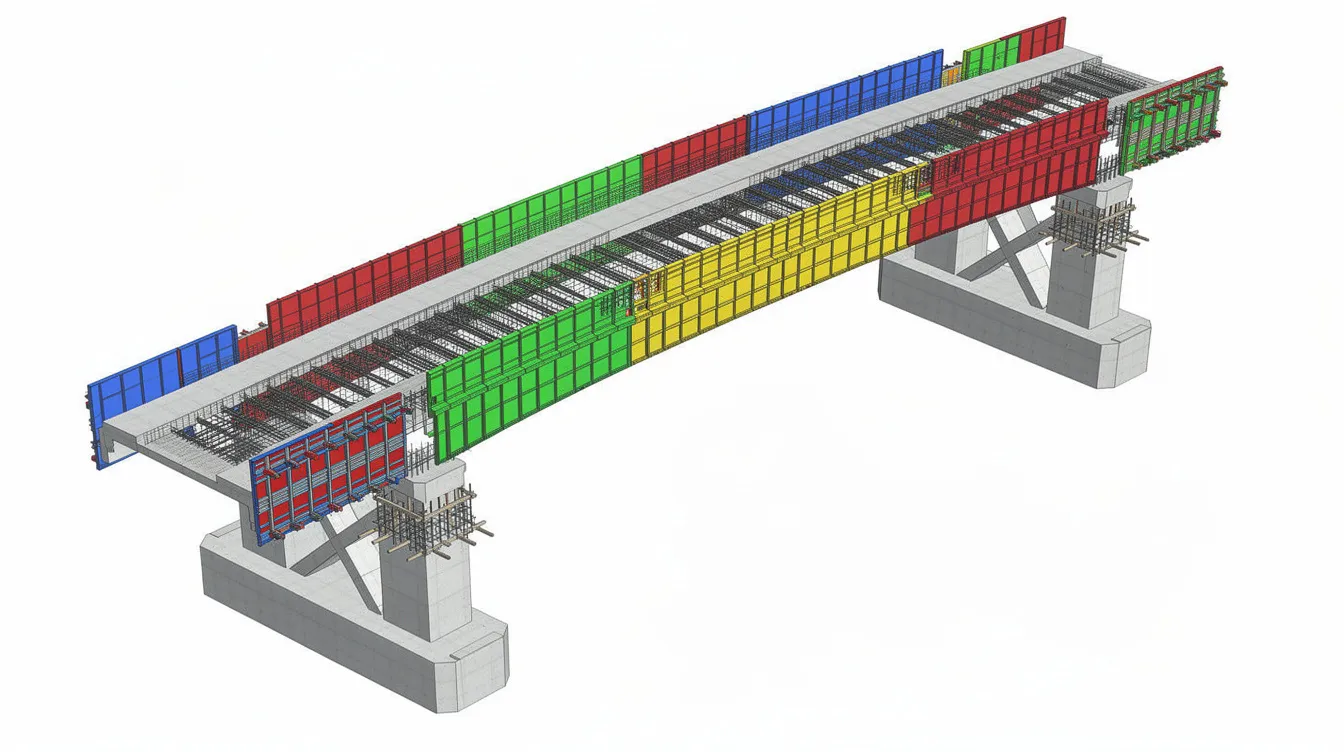
AMAN Engineering integrates formwork systems into federated BIM models for major infrastructure jobs using Tekla 3D modelling, enabling more accurate early coordination before site mobilisation. With BCA’s CORENET-X platform launching in October 2026, BIM-based submissions and digital workflows will become standard for regulatory checks on many project types.
Common Formwork Drawing Problems and How PE Review Solves Them
Many construction delays come from recurring, avoidable drawing issues that a disciplined PE review catches before formwork reaches the construction site. Each problem below is drawn from patterns observed on Singapore and ASEAN infrastructure works.
Problem 1: Inadequate Support for High Walls and Piers
Tall retaining walls or bridge piers frequently arrive on site with insufficient walers, ties, or bracing for the specified rate of pour. The root cause is usually an underestimate of fresh concrete lateral pressure. A PE review checks lateral pressure based on actual concrete properties (density, temperature, admixture type) and pour rate, then adjusts tie spacing, waler sizes, and bracing accordingly. For pours exceeding 4 m in height, LTA specifications require PE design and a Certificate of Supervision before casting can proceed.
The time saved by catching this on paper is substantial: bulging or honeycombing from overstressed formwork demands demolition and recasting, which can add weeks to a wall pour programme.
Problem 2: Formwork Clashes with Reinforcement and Embedded Items
Form ties conflicting with dense rebar cages or post-tensioning ducts in bridge decks is one of the most common clash types. Supports blocking access to anchor bolts, inserts, or box-outs for MEP systems is another, and where openings are involved, the same issue can affect a window frame. These conflicts surface during rebar installation or immediately before a pour, forcing last-minute on-site drilling, core-cutting, or reinforcement adjustments.
PE review combined with BIM coordination or coordinated 2D overlays identifies and relocates these items during the drawing phase. The reduction in last-minute site modifications translates directly into fewer cancelled pours and shorter rebar fix cycles. Shop drawings ensure components fit together correctly on-site, and the same checking logic applies when they must align with surrounding construction details and the exact details of embedded components; without that assurance, the construction team is left improvising.
Problem 3: Unsafe or Non-Compliant Access and Working Platforms
Missing guardrails on platforms attached to formwork for soffit works under bridges, insufficient clear width on access platforms in shafts and underpasses, and incorrect ladder angles are common omissions in contractor drafts. These items are secondary to the formwork’s structural function but primary to safety compliance.
A PE review ensures compliance with safety regulations like the Workplace Safety and Health Act and client safety standards. Detailing toe boards, mid-rails, safe ladder angles, and platform widths in the approved shop drawings prevents safety stoppages and non-conformance reports. Under WSH Act penalties, fines for safety offences can reach SGD 500,000 for certain categories of breach.
Problem 4: Overly Complicated or Material-Heavy Configurations
Without engineering optimisation, formwork systems tend toward overdesign: too many prop lines, unnecessary heavy steel frame sections, or bespoke fabricated members that cannot be reused. A PE rationalises the scheme by standardising specific components, reducing the number of unique members, and verifying that standard catalogue items can carry the required loads.
Simplified, standardised solutions reduce training time for new crews and speed up every pour cycle. On a multi-span viaduct, the difference between a layout with 15 unique panel types and one with 5 standard types is measurable in hours per pour, compounding across dozens of pours.
Case-Style Scenarios: Time Savings from PE-Reviewed Formwork on Infrastructure Projects
These are indicative scenarios based on typical Singapore and ASEAN infrastructure work. Specific client names are omitted, but the technical details and approximate time savings reflect real project patterns.
Scenario 1: Elevated Road Viaduct Formwork Cycle Optimisation
A 4-span, post-tensioned viaduct used table formwork and shoring towers, with casting restricted to night shifts due to traffic diversions. The initial formwork layout required excessive shoring towers because prop capacities had not been verified against actual slab loads. Relocation time between spans consumed two full shifts per span, and frequent inspection comments on bracing adequacy added further delays.
PE-led reconfiguration achieved three things: verified prop capacities allowed fewer towers through better load distribution; a repeatable table layout was standardised across all four spans; and bracing details satisfied the RE’s requirements on first submission. The pour cycle per span dropped from 10 days to 7 days. Over four spans, that was 12 days recovered for downstream activities.
Scenario 2: Deep Retaining Wall Formwork at a Water Treatment Plant
A deep RC retaining wall for a treatment tank had congested reinforcement and multiple pipe penetrations for inlet/outlet valves. The initial formwork construction drawings conflicted with pipe blockouts: tie locations fell directly behind embedded sleeves, and waler positions blocked access for rebar installation around valve boxes.
PE review actions included 3D coordination of ties and walers with embedded pipes and valves, and resequencing pours to allow easier rebar and embedded installation. The project avoided at least two cancelled pour dates that would have cost approximately 1.5 to 2 weeks of cumulative delay when accounting for remobilisation, concrete resupply, and re-inspection.
Scenario 3: MRT Station Box Slab and Beam Formwork Under Tight Programme
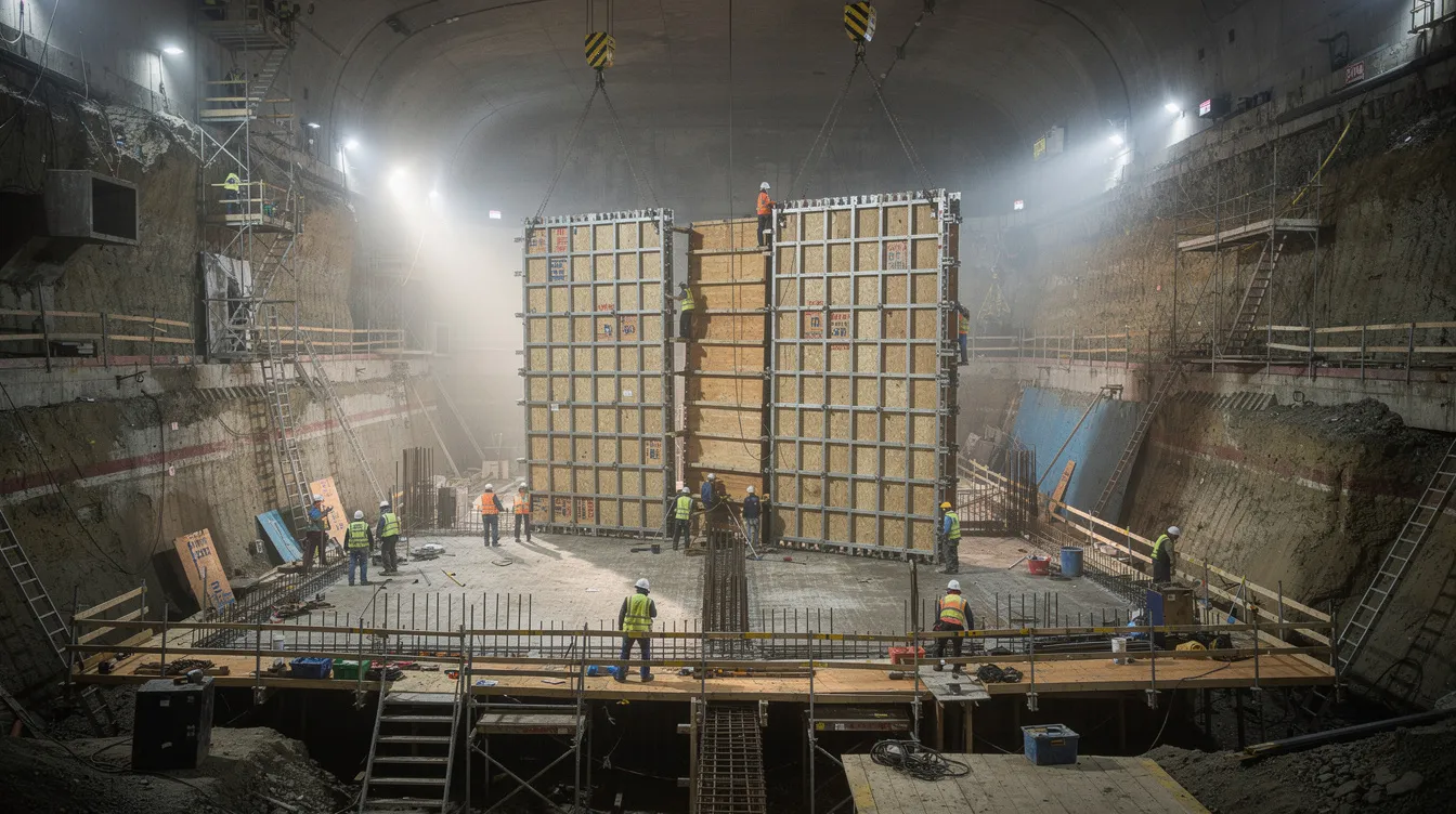
An underground station box had large transfer beams (1.8 m deep) and thick slabs requiring heavy-duty soffit formwork. The initial construction shop drawings underestimated support height for the lowest level and omitted re-shoring arrangements for the slab above. Without re-shoring, striking the lower formwork would have overloaded the freshly cast upper slab before it reached adequate strength.
PE intervention recalculated loads for multi-storey propping and produced clear phasing drawings tied to concrete cube strength milestones. The contractor could schedule striking ages confidently, and predictable re-use of shoring released basement levels for M&E trades earlier than the original programme anticipated. Shop drawings improve project coordination among various project teams; in this case, the M&E subcontractor gained access three days ahead of the baseline programme.
Conclusion and Next Steps
PE-reviewed formwork shop drawings convert temporary works from a recurring source of delay and risk into a controlled, optimised process. The core benefits are specific and measurable:
- Structural safety verified against actual loads, with regulatory compliance under WSH Regulations and SS 580:2020 confirmed before mobilisation.
- Fewer RFIs, rework events, and failed inspections, because coordination gaps are resolved on paper.
- Shorter pour cycles from standardised panel layouts and verified prop capacities, compounding into weeks of programme recovery over multi-span or multi-level structures.
- More efficient use of formwork materials across the project, reducing procurement lead times and material waste.
Practical next steps:
- Audit current formwork shop drawing workflows on one live project to identify where coordination gaps exist.
- Identify pours or elements with the highest risk: deep walls, transfer structures, bridge decks, and any formwork exceeding the statutory PE design thresholds.
- Engage a PE-led review on those packages early, before fabrication and delivery of formwork systems.
- Integrate formwork layouts into BIM coordination meetings where possible.
AMAN Engineering Consultancy Pte Ltd provides formwork and temporary works design and PE endorsement for infrastructure projects in Singapore and the wider ASEAN region. The firm also supports BIM-based coordination of formwork with structural, architectural, and M&E models, and handles authority submission workflows where temporary works design must be demonstrated to clients or regulators.
FAQs on PE-Reviewed Formwork Shop Drawings
Do all formwork shop drawings need PE endorsement in Singapore?
Statutory mandates may require PE design for complex formwork structures in Singapore. Under the WSH (Construction) Regulations 2007, PE design is mandatory for formwork exceeding 9 m height, formwork supported on two or more tiers of shores, and slab/beam formwork thicker than 300 mm. LTA specifications add a requirement for wall formwork 4 m or taller. Smaller or proprietary system applications may be accepted under supplier design, but many main contractors still request PE review for risk management and to satisfy project specifications.
At what project stage should PE review of formwork drawings happen?
PE review should occur before ordering special components or fabricating steel frames, and before locking in pour sequences in the master programme. The practical rule is to allow enough float for one review and one revision cycle. Submitting drawings to a PE three days before a planned pour defeats the purpose; the review becomes a rubber-stamp exercise rather than a genuine engineering check. Early coordination between the contractor and PE prevents the feedback loops that consume programme time later.
How long does PE review usually take, and does it delay work?
For well-prepared drawings with complete input data, PE review for a typical wall or slab package takes 3 to 7 working days. Larger bridge or station packages may need 1 to 2 weeks. This pre-construction review time is a fraction of the delay caused by a single cancelled pour (often 2 to 3 days of remobilisation) or a failed MOM inspection. Architects or engineers review shop drawings for accuracy; the time invested upfront consistently saves more time on site than it consumes.
What information should contractors provide to the PE for an effective review?
The PE needs these inputs to review project requirements against the proposed formwork scheme:
- Latest IFC drawings and models, checked against construction documents, including structural plans where needed, with levels, cambers, and exact measurements of structural members.
- Concrete specifications, pour rates, sequence, and construction loads (equipment, storage, traffic where relevant).
- Formwork system catalogues and manufacturer data sheets with material details and component capacities.
- Site constraints: headroom, crane reach, access limitations, and ground bearing capacity.
Incomplete information extends the review cycle and limits the PE’s ability to optimise the formwork scheme.
Can BIM help with formwork, or is 2D enough?
While 2D is still widely used on smaller pours, BIM provides better visualisation and clash detection for complex geometries: curved viaducts, intersecting walls, station boxes with congested reinforcement, and, where relevant, interfaces to millwork shop drawings in mixed-use podium or station fit-out zones. AMAN Engineering works with both 2D and 3D inputs, but clients seeking maximum time savings on large construction projects increasingly prefer BIM-integrated workflows because BIM helps communicate complex details more clearly across trades. The additional details captured in a 3D model pay for themselves when they prevent even one pour cancellation.
How does AMAN Engineering Consultancy differ from a formwork supplier’s in-house design team?
AMAN acts as an independent PE and engineering consultant. The firm reviews multiple formwork systems objectively, aligning solutions with the overall structural design intent, site risks, and authority requirements rather than optimising for a single supplier’s product range, while coordinating structural, architectural, and MEP models to support broader outcomes and improve project quality. AMAN also integrates formwork with broader temporary works design, safety coordination, and authority submission services for infrastructure jobs, covering project needs that fall outside a supplier’s scope and helping improve project quality beyond the formwork package itself.