
Introduction
Alkali silica reaction (ASR) is a destructive chemical reaction that occurs within concrete when reactive silica in aggregates reacts with alkali hydroxides in the cement paste’s pore solution, producing an expansive ASR gel that absorbs moisture and generates internal pressures. Preventing alkali silica reaction ASR identification and mitigation strategies form the backbone of any durable concrete program-particularly in humid tropical climates like Singapore and the broader ASEAN region, where moisture levels consistently exceed the 80–85% relative humidity threshold that fuels this deleterious alkali aggregate reaction.
This article covers the full lifecycle of ASR management: from understanding the underlying chemical reaction, through field identification of signature map cracking and gel exudation, to laboratory tests that confirm diagnosis, design-stage prevention in new concrete mixtures, and remedial treatments-including lithium-based chemical treatments and moisture-barrier coatings-for existing concrete structures already exhibiting deterioration. The guidance applies to developers, engineering consultants, asset owners, facility managers, and contractors responsible for commissioning or maintaining concrete infrastructure in environments where ASR risk is elevated.
In brief, ASR prevention combines selecting non-reactive aggregates, controlling alkali content through low-alkali portland cement and supplementary cementitious materials, managing moisture through design detailing and waterproof membranes, and-where ASR is already active-applying lithium nitrate treatments and surface protection systems to slow further expansion. Recognizing ASR signs early is essential for structural longevity.
After reading this article, you will understand:
-
How to visually recognize ASR, especially the characteristic “map cracking” pattern and exuded gel
-
Which laboratory tests and field inspections confirm ASR and inform mitigation decisions
-
Design-stage measures-aggregate selection, SCMs, alkali limits, moisture detailing-to prevent ASR in new projects
-
Remedial and mitigation strategies, including lithium salt treatments and moisture-barrier coatings, for existing ASR-affected structures
-
How professional engineering consultancy supports ASR risk assessment and mitigation in Singapore and the region
Understanding Alkali–Silica Reaction in Concrete
Alkali silica reaction is a slow but relentless process of concrete deterioration. It attacks the very bond between aggregate particles and the surrounding concrete matrix, progressively weakening structures that were designed to last decades-bridges, viaducts, highways, water-retaining structures, industrial floors, and building façades. Because ASR damage can manifest years after initial exposure to moisture, the reaction often goes undetected until cracking is widespread and repair costs are substantial.
At a high level, reactive forms of silica within aggregates dissolve in the highly alkaline conditions of the pore solution, producing a hygroscopic alkali–silica gel. This gel absorbs water from the surrounding environment, swells, and exerts expansive pressures within the concrete matrix that exceed the tensile strength of the cement paste-resulting in microcracking, surface map cracking, and progressive loss of structural integrity.
Chemical Mechanism and Conditions for ASR
ASR occurs between reactive silica in aggregates and cement alkalis-specifically sodium hydroxide and potassium hydroxide-dissolved in the pore solution. The hydroxyl ions attack poorly crystalline or amorphous silica minerals (such as opal, chalcedony, volcanic glass, and strained quartz), breaking Si–O–Si bonds and forming an alkali–silica gel. This gel is hygroscopic: it draws in moisture, expands, and generates internal stress that fractures both aggregate particles and the surrounding cement paste.
Three conditions must be present simultaneously for deleterious expansion to occur:
-
Reactive aggregates containing amorphous silica, microcrystalline quartz, or other forms of reactive silica susceptible to breakdown under alkaline conditions
-
Sufficient alkali content in the pore solution-typically quantified as Na₂O equivalent ≥ 0.6% in cement, or total alkali loading exceeding approximately 2.5 kg Na₂O equivalent per cubic metre of concrete
-
Continuous moisture supply, generally requiring internal relative humidity above 80–85% for sustained gel swelling and ASR related expansion
In tropical, high-humidity environments like Singapore-where ambient RH routinely exceeds 80% and rainfall is frequent-condition (3) is almost always satisfied for exposed concrete. This makes aggregate reactivity screening and alkali control especially critical in the region. It is also worth noting that ASR is distinct from alkali–carbonate reaction (ACR), another form of deleterious alkali aggregate reaction involving dolomitic limestones; notably, no proven measures exist for alkali carbonate reactive rocks, making correct identification of the reaction type essential.
How ASR Affects Structural Performance Over Time
ASR progresses through identifiable stages. The latent period-which can last months to several years-features internal microcracking within reactive aggregate particles and at the paste-aggregate interface, often invisible to the naked eye. As the reaction continues and gel accumulates, visible surface map cracking emerges, joints become misaligned or close unexpectedly, and pop-outs appear where highly reactive aggregate particles fracture and eject from the surface.
The detrimental effects extend beyond aesthetics. ASR-induced cracking opens pathways for chlorides, carbon dioxide, and other aggressive agents to penetrate the concrete, accelerating reinforcement corrosion and compounding concrete deterioration. Structural stiffness decreases, deflections increase, and length change measurements may show expansion well beyond design tolerances. While ASR rarely causes sudden collapse by itself, it substantially reduces serviceability and complicates long-term maintenance of bridges, reservoirs, highways, and façades.
Early identification in the field-before deterioration becomes structurally significant-is therefore the critical first step toward any effective mitigation strategy.
Field Identification of ASR in Existing Structures
Many asset owners first suspect ASR when unexplained cracking appears on concrete surfaces that should otherwise be sound. Visual diagnosis, when conducted systematically during routine inspections, provides the starting point for any mitigation plan. Understanding what to look for-and how to document it-can save time and prevent costly misdiagnosis.
Recognizing Signature ASR “Map Cracking”
Visual indicators of ASR include map cracking and gel exudation from cracks. Map cracking-also called pattern cracking-is the hallmark visual signature of ASR. It presents as a network of intersecting cracks forming irregular polygonal shapes, typically 50–300 mm across, distributed relatively uniformly across the affected surface without clear alignment to reinforcement layout or structural load paths.
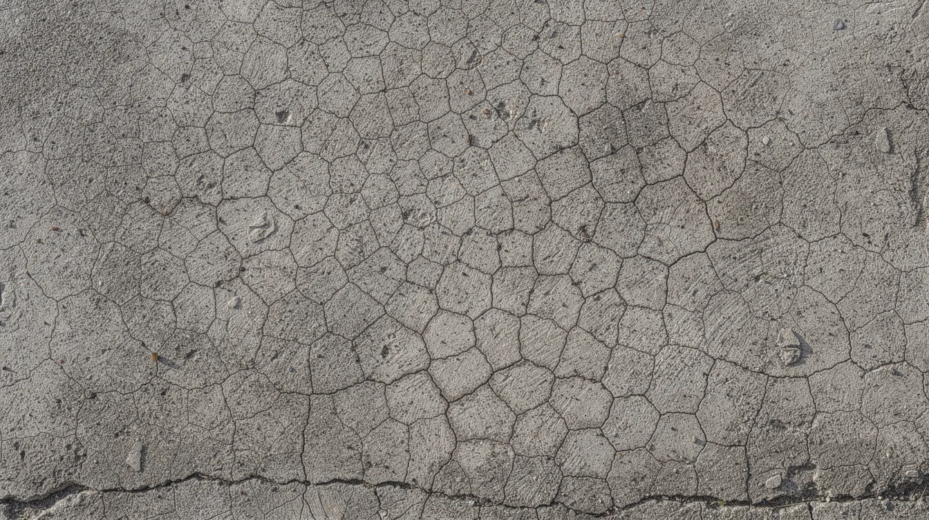
Map cracking from ASR differs from other cracking mechanisms in several important ways:
-
Plastic shrinkage cracks tend to be straight, parallel lines appearing within hours of placement
-
Drying shrinkage cracks are more uniform and often extend through the full depth of slabs
-
Structural flexural or shear cracks orient relative to loading directions and follow predictable patterns based on member geometry and reinforcement detailing
Inspectors and engineers should use high-resolution photography-both wide-angle views capturing the overall crack network and close-up shots showing individual crack widths and gel deposits-with annotation overlays to highlight the polygonal pattern. Crack widths in advanced ASR can reach 0.5–2.0 mm or more after several years of progression.
Map cracking is most commonly identified on parapet walls, bridge decks, exposed beams and columns, precast façade panels, and water-retaining structures-any element with sustained moisture exposure and limited ability to dry out.
Other Visual and Physical Indicators of ASR
Beyond map cracking, several additional field signs point toward active ASR:
-
Gel exudation: opaque or translucent ASR gel oozing from cracks or around aggregate particles, sometimes accompanied by brownish or whitish staining. This gel should be distinguished from calcium carbonate efflorescence, which is typically white, powdery, and associated with carbonation rather than reactive silica breakdown.
-
Joint distortion: closed joints that have opened, misaligned, or shifted as the concrete expands
-
Pop-outs: shallow conical fragments ejected from the surface where reactive aggregate particles have fractured beneath the surface
-
Surface roughness and scaling: localised unevenness linked to subsurface cracking and expansion
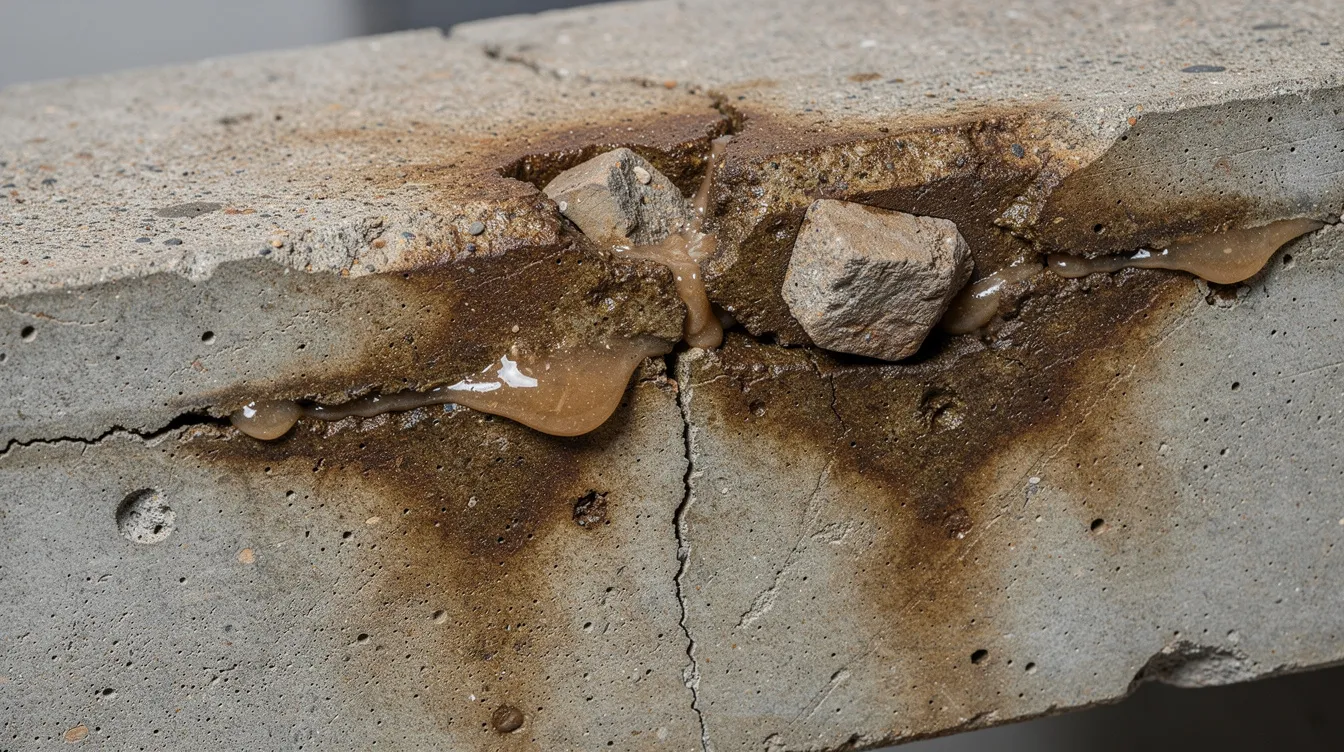
Moisture patterns such as persistent wet bands and efflorescence often coincide with ASR-affected zones, providing useful mapping cues. When distinguishing ASR gel from efflorescence, note that ASR gel is typically sticky or viscous when fresh, dries to a glossy or vitreous sheen, and appears within or immediately adjacent to cracks, whereas efflorescence is dry and chalky.
Role of Structural and Façade Inspections (PSI, PFI) in ASR Detection
Scheduled Periodic Structural Inspections (PSI) and Periodic Façade Inspections (PFI) prescribed by Singapore authorities provide an invaluable-and often underutilised-opportunity to screen for ASR-related map cracking and deterioration on ageing concrete structures.
During these inspections, engineers and qualified persons should:
-
Use crack width gauges and high-zoom photography to systematically record crack patterns, widths, and progression
-
Map ASR-affected areas on elevation drawings, plan layouts, or BIM models for spatial tracking over time
-
Flag suspect ASR zones for further laboratory confirmation by petrographic examination or chemical spot tests
-
Document moisture sources (drainage failures, missing drip edges, ponding areas) adjacent to cracked zones
Integrating photographic documentation with BIM or Tekla models allows geo-referencing of observed ASR patterns for future comparison-enabling data-driven decision-making on whether and when mitigation is warranted. This approach aligns with the broader trend toward structural assessment as a compliance requirement in Singapore.
With field observations documented, the next step is laboratory confirmation to determine whether ASR is indeed the primary mechanism driving the observed deterioration.
Laboratory Assessment and Confirmation of ASR
Visual symptoms alone are not sufficient to confirm ASR as the dominant deterioration mechanism. Cracking from drying shrinkage, thermal cycling, sulfate attack, and corrosion can mimic ASR patterns. Laboratory tests provide definitive confirmation and inform the choice of mitigation strategy-whether that involves surface treatments, chemical admixtures, structural strengthening, or a combination.
Petrographic Examination and Gel Identification
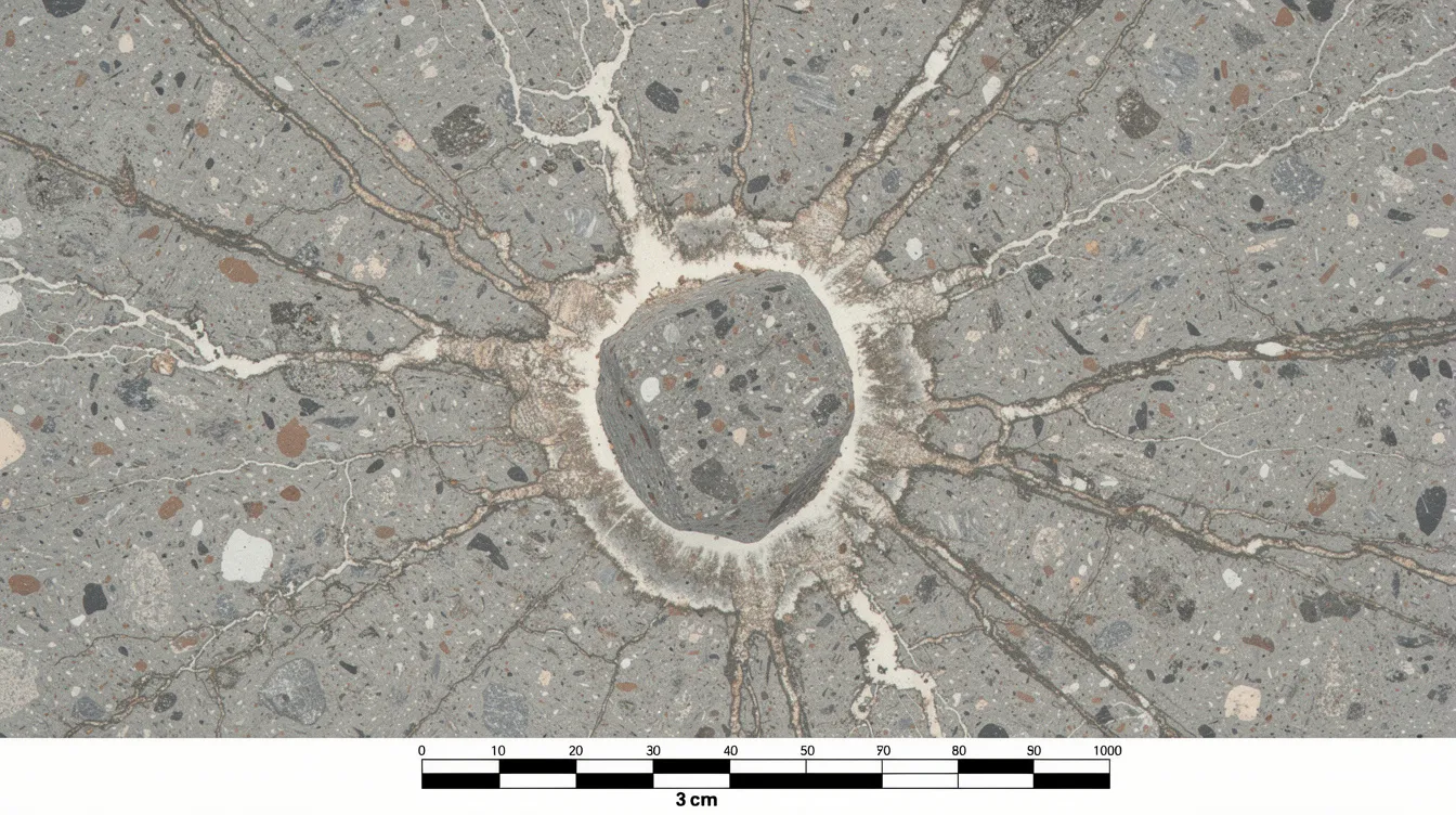
Petrographic examination of concrete cores is the “gold standard” for confirming ASR. Following protocols such as ASTM C856 and ASTM C295, petrographers prepare thin sections and examine them under optical microscopy and, where needed, scanning electron microscopy with energy-dispersive spectroscopy (SEM-EDS). Petrographic examination confirms presence of ASR gel in concrete cores by identifying:
-
Cracked reactive aggregate particles with gel-filled fissures radiating outward into the cement paste
-
ASR gel deposits within air voids, at the paste-aggregate interface, and along crack networks
-
Characteristic crack networks oriented independently of reinforcement layout, confirming internal expansion as the driving force
Staining techniques-using uranyl acetate fluorescence or alizarin-based dyes-highlight gel deposits that might be missed under standard illumination. This differentiation is critical: it separates ASR from other mechanisms and prevents costly misallocation of repair resources.
Accelerated Reactivity and Expansion Tests on Aggregates and Concrete
Several standardised laboratory tests evaluate whether aggregates or concrete mixes are susceptible to deleterious expansion:
-
Accelerated Mortar Bar Test (ASTM C1260): Mortar samples containing the candidate fine aggregates are immersed in sodium hydroxide solution at 80°C. The Accelerated Mortar Bar Test is used to evaluate aggregate reactivity, with results available within approximately 16 days. Expansion exceeding specified thresholds indicates potentially reactive aggregates. ASTM C1778-22 provides guidance for identifying ASR aggregates and interpreting these test results.
-
Concrete Prism Test (ASTM C1293): Concrete specimens are stored at elevated temperature and humidity for up to two years. The Concrete Prism Test provides a long-term assessment of ASR potential and is considered more reliable than accelerated methods for confirming field performance. The AASHTO T 380 test defines passing expansion as ≤ 0.04%.
-
ASTM C1567: Evaluates the effectiveness of supplementary cementitious materials in reducing ASR expansion when blended with reactive aggregates-essential for calibrating SCM replacement levels in new concrete mixes.
Routine testing can reduce the risk of ASR expansion by catching reactive aggregates before they enter the supply chain. These tests are essential for new projects and equally valuable for evaluating potential SCM blends or lithium treatments for remediation of existing structures.
Field Test Kits and On‑Site Screening Tools
Rapid field tests for ASR gel-such as chemical spot tests using alizarin dye or fluorescent stains applied to freshly broken concrete surfaces-serve as preliminary screening tools. They can quickly flag areas of concern during inspections but do not constitute final proof of ASR.
Their limitations are significant: false positives can occur from other gel-like deposits, and false negatives are possible if gel has dried or carbonated. Field test results should always be combined with petrographic analysis and a broader structural assessment. Documenting field test results through close-up photography creates a valuable record that accompanies laboratory reports and supports traceable decision-making.
Confirmed ASR diagnosis leads directly to the question of strategy: how to prevent the reaction in new projects and how to mitigate its effects in structures already affected.
Design-Stage Strategies to Prevent ASR in New Concrete
The lowest-cost ASR strategy is prevention at the design and specification stage-before concrete is cast. Preventing ASR through proper mix design, aggregate selection, and detailing avoids the substantially higher lifecycle costs of remediation, monitoring, and potential structural strengthening. Mitigation strategies focus on interrupting components required for ASR, and specifications should be embedded in contract documents, method statements, and BIM-linked models.
Selecting and Specifying Non‑Reactive or Low‑Reactivity Aggregates
Identifying reactive aggregates is critical for concrete durability. Use non-reactive aggregates to prevent ASR during construction by sourcing materials with documented historical performance and by requiring suppliers to provide ASTM C295 petrographic certificates and ASTM C1260 mortar bar test results for each batch or source.
Aggregate sources should be evaluated against established expansion limits, and historical field performance data-where available-should inform selection. In regions with limited aggregate sources, where all locally available materials may contain some reactive silica, aggregate selection must be combined with other mitigation measures such as SCMs and alkali limits rather than relied upon alone. Preventive measures depend on aggregate reactivity and exposure conditions, and the specification should reflect this calibrated approach.
Controlling Alkali Content and Using SCMs
Alkali control begins with specifying low-alkali portland cement-Na₂O equivalent not exceeding 0.6%-and capping total alkali content of concrete at 2.5 kg Na₂O equivalent per cubic metre, consistent with Singapore’s BCA Approved Document requirements and BRE Digest 330 guidance. All alkali contributions-from cement, admixtures, mixing water, and recycled materials-must be accounted for in the total.
Incorporate supplementary cementitious materials to bind alkalis and reduce ASR expansion. Fly ash is commonly used to mitigate ASR, and other SCMs including ground blast furnace slag, silica fume, and metakaolin are highly effective when used at appropriate replacement levels:
-
Fly ash or slag: typically 20–35% replacement by mass, with local calibration based on expansion testing
-
Silica fume: typically 5–10% replacement, effective at reducing pore solution alkalinity and permeability
-
Metakaolin: similar performance to silica fume but with different availability and cost profiles
-
Emerging options: diatomaceous earth and natural pozzolans are potential ASR mitigators, and previous studies indicate that nano-silica admixtures can help reduce ASR effects
SCMs work through multiple mechanisms: they dilute the cement’s alkali contribution, consume calcium hydroxide to form additional C-S-H that binds alkalis, and reduce permeability of the concrete matrix-decreasing moisture ingress. Performance-based verification of proposed SCM combinations through expansion tests (ASTM C1567) is essential, as the effectiveness of any given SCM depends on its chemistry, fineness, and the specific reactive aggregates in the mix.
Mixture design choices must also satisfy strength, setting time, and durability requirements specified in local codes and authority submissions-ensuring that ASR prevention does not compromise other performance criteria.
Designing for Moisture Management and Detailing
Since moisture control is vital to prevent ASR progression, structural detailing that reduces long-term moisture availability is a powerful complementary strategy:
-
Adequate drainage falls on decks, roofs, and podium slabs to prevent ponding
-
Drip edges and proper waterproofing of exposed beams, parapets, and slab edges
-
Roof membranes and overhangs that shield concrete from direct rain exposure
-
Joint design that prevents water ingress while accommodating thermal movement
While full moisture elimination is unrealistic in Singapore’s tropical climate-where ambient RH consistently exceeds 80%-better detailing meaningfully reduces the severity and extent of ASR-prone zones by limiting the duration and intensity of wetting cycles. These design principles connect directly to the moisture-barrier systems discussed below for existing structures.
Mitigation Strategies for Existing ASR-Affected Structures
Once ASR is active in a structure, it cannot be reversed or undone. The expansive gel has formed, cracks have propagated, and the internal fabric of the concrete matrix has been permanently altered. However, progression can be significantly slowed, and structural consequences managed through targeted mitigation methods. Choosing the right approach depends on the structure’s criticality, the severity of ASR, intended residual service life, and available budget.
Chemical Treatments: Lithium-Based Admixtures and Surface Applications
Chemical admixtures like lithium-based products can help suppress ASR expansion. The principle is straightforward: lithium salts-most commonly lithium nitrate-alter the chemistry of ASR gel formation, producing a non-expansive lithium-alkali-silica compound instead of the swelling gel that causes damage.
Two distinct applications exist:
-
Internal lithium admixtures in new concrete: added during batching as a preventive measure in concrete mixes containing marginally reactive aggregates
-
Surface-applied lithium treatments on existing structures: typically a 30% lithium nitrate solution applied by low-pressure spray or ponding at approximately 0.12 L/m², sometimes with multiple applications or vacuum impregnation to improve penetration
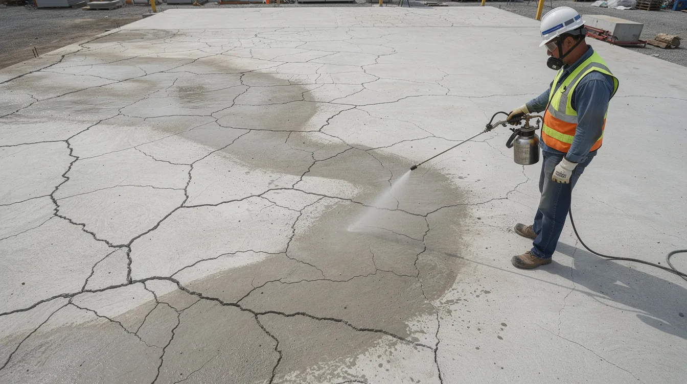
In FHWA field trials, median concrete barrier sections treated with lithium nitrate showed measurable reductions in expansion compared to untreated control sections across several years of monitoring. However, realistic expectations are essential: lithium penetration depth is often limited to approximately 50 mm in moderately cracked elements, and even less in dense, uncracked concrete. The treatment may significantly reduce future expansion but does not close existing cracks or reverse existing damage.
Selection and dosage should be based on specialist advice, and where possible, trial areas with monitored crack movement should be established before committing to full-scale application. Surface preparation-removing loose material, ensuring the substrate is clean-is critical for effective absorption.
Moisture-Barrier Coatings and Surface Protection Systems
Limiting moisture ingress is one of the most effective mitigation strategies to slow ASR progression in service, given that moisture is the “fuel” that drives gel swelling and further expansion. Several barrier system types are available, each suited to different exposure conditions:
-
Hydrophobic impregnations (silane/siloxane): penetrating treatments that line concrete pores with a water-repellent layer while maintaining vapour permeability. Silane typically penetrates 2.5–6 mm depending on concrete density and application method. Sealer systems have shown reductions in ASR expansion by 40–60% compared to untreated concrete in laboratory and field studies.
-
Film-forming coatings (epoxy, polyurethane, polyurea): provide a continuous moisture barrier on decks, slabs, and contained environments. Higher moisture resistance but lower vapour permeability-creating a risk of trapping moisture behind the coating if the substrate is not adequately dry at application.
-
Waterproof membranes: sheet or liquid-applied roofing and podium membranes that prevent rain and groundwater from reaching concrete surfaces. Effective for large horizontal surfaces and substructures.
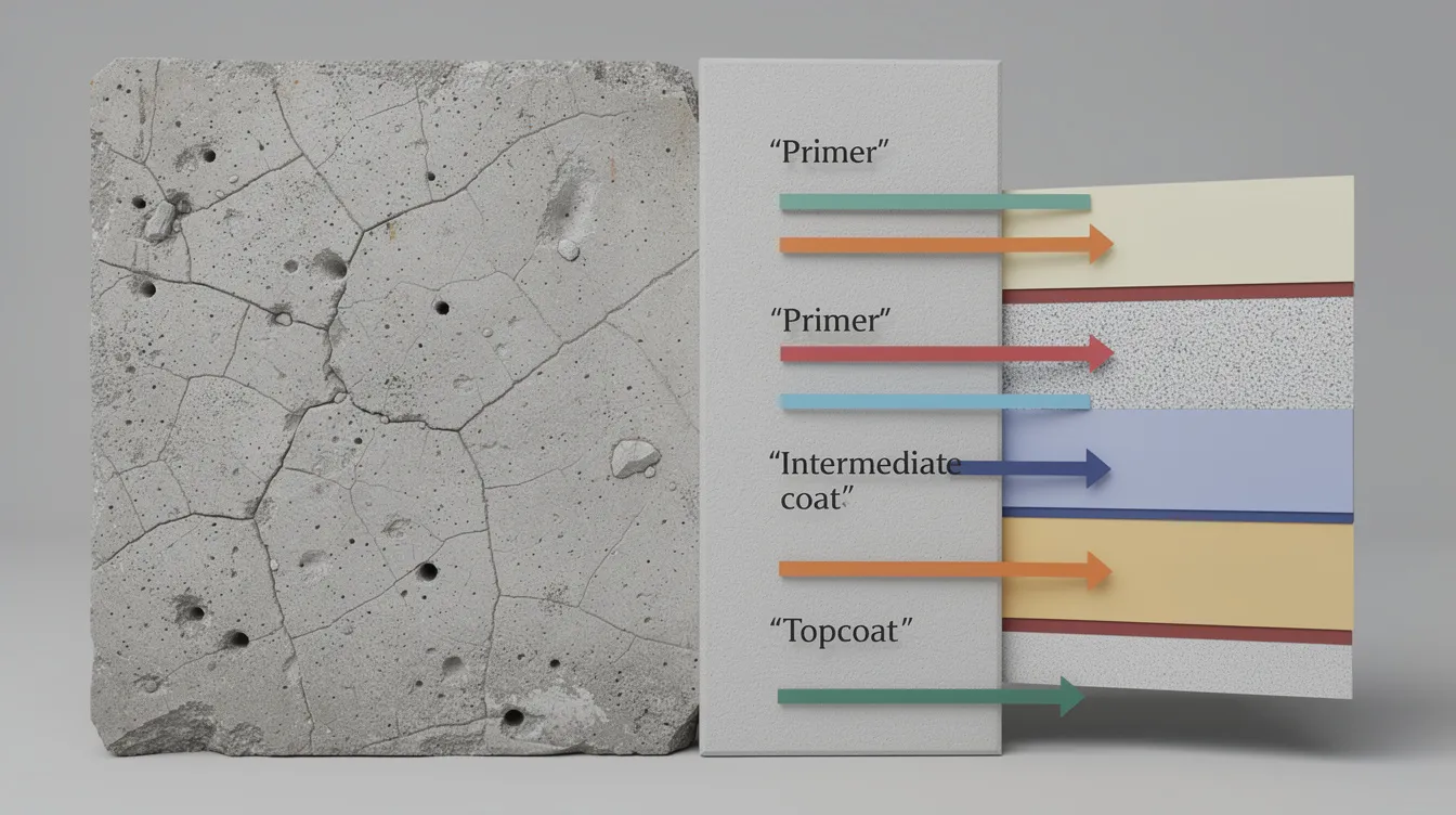
Key design considerations for moisture-barrier systems include:
-
Vapour permeability balance: silane-based systems allow trapped moisture to escape while blocking liquid water ingress, making them preferable for many applications on façades and bridge elements. Impermeable coatings risk moisture entrapment, which can paradoxically worsen ASR.
-
Surface preparation: cracks wider than approximately 0.3 mm should be sealed before coating application; surfaces must be clean, dry, and free of laitance.
-
Maintenance cycles: UV degradation, abrasion, and environmental wear degrade surface treatments. Reapplication every approximately 5 years is commonly recommended.
-
Compatibility: ensure coating systems are compatible with existing repairs and reinforcement protection.
In laboratory exposure of concrete specimens with opaline flint aggregates over nearly three years, those impregnated with silane-based surface treatment maintained significantly lower internal RH, and in some cases showed no perceptible ASR expansion, while untreated specimens expanded substantially.
Repair strategies for existing ASR-affected concrete may include sealing and drainage improvements alongside coating systems-addressing both surface moisture ingress and water management around the structure.
Structural Strengthening, Crack Management, and Monitoring
When ASR has progressed to the point of compromising structural integrity, physical interventions become necessary:
-
Loss of stiffness affecting serviceability through excessive deflection
-
Significant cross-section loss or spalling at critical locations
-
Functional impairments such as doors or windows binding, bearings misaligning, or joints closing
Possible structural interventions include:
-
External FRP wrapping or steel jacketing to restore load-carrying capacity
-
Concrete section enlargement or bonded overlays using low-alkali, ASR-resistant concrete mixes
-
Crack injection with epoxy or elastic resins for structural continuity and watertightness
-
Rectification of structural defects through partial or full member replacement where damage is severe
Monitoring is equally important as physical repair. Installing crack gauges or digital displacement sensors on critical cracks, establishing periodic re-inspection intervals of 6–12 months tied into PSI/PFI routines, and using BIM models or digital twins to track progression spatially over time ensures that mitigation effectiveness is measured and adjustments made as needed.
Comparing ASR Prevention and Mitigation Options
No single measure suits all projects. The best solution for any given structure depends on whether ASR is being prevented in new construction or mitigated in an existing asset, and on the balance between lifecycle cost, performance expectations, and constructability constraints.
Performance, Cost, and Practicality Comparison
|
Criterion |
Low-Alkali Cement + SCMs |
Lithium Admixture (New Mix) |
Surface Lithium Treatment (Existing) |
Silane/Siloxane Impregnation |
Film-Forming Coating |
Structural Strengthening |
|---|---|---|---|---|---|---|
|
Primary Purpose |
Prevention |
Prevention |
Mitigation |
Mitigation |
Mitigation |
Strengthening/Repair |
|
Relative Cost |
Low–Medium |
Medium |
Medium–High |
Low–Medium |
Medium |
High |
|
Effectiveness in Reducing ASR Expansion |
High (when properly dosed) |
High |
Moderate (depth-limited) |
Moderate–Good (40–60% reduction) |
Good (if substrate dry) |
N/A (addresses consequences) |
|
Key Limitations |
Requires reliable SCM supply; affects early strength |
Cost of lithium compounds; availability |
Shallow penetration (~50 mm); multiple applications needed |
Reapplication every ~5 years; limited on wide cracks |
Risk of moisture entrapment; surface prep critical |
High cost; access constraints; combined with chemical/moisture measures |
|
Maintenance Requirement |
None (built-in) |
None (built-in) |
Monitoring + possible reapplication |
Periodic reapplication |
Periodic reapplication |
Ongoing monitoring |
For designers and quantity surveying teams, mix-based prevention using low-alkali cement and supplementary cementitious materials offers the most cost-effective long-term solution for new concrete structures. For owners of existing assets, the decision between life-extension through coatings and chemical treatments versus partial replacement depends on the severity of ASR, criticality of the structure, and residual design life.
A combined approach-lithium treatment plus moisture-barrier coating, supported by ongoing monitoring-often provides the most effective mitigation strategies for moderately affected structures where replacement is not yet warranted.
Common Challenges and Practical Solutions
Even with sound technical solutions available, implementation is frequently constrained by supply chain realities, site access limitations, and regulatory considerations. Each challenge below describes a typical real-world problem with concrete, actionable responses.
Challenge 1: Limited SCM Availability or Variable Quality
Reduced fly ash supply-driven by declining coal-fired power generation in some regions-and inconsistent blast furnace slag quality can undermine mix design strategies that rely on fixed SCM replacement percentages.
Solutions:
-
Use blended cements or alternative SCMs such as metakaolin, finely ground glass pozzolan, or natural pozzolans where traditional materials are unavailable
-
Adopt performance-based specifications using expansion testing (ASTM C1567) instead of prescriptive replacement percentages, allowing flexibility in materials while maintaining ASR control
-
Engage suppliers and accredited laboratories early in project planning to confirm material availability and verify effectiveness through mortar bar or concrete prism testing
Challenge 2: Diagnosing ASR in Structures with Multiple Deterioration Mechanisms
ASR frequently coexists with reinforcement corrosion, sulfate attack, or carbonation-induced damage, making diagnosis ambiguous when based on visual inspection alone. Cracking from multiple sources can overlap, obscuring the contribution of each mechanism.
Solutions:
-
Commission combined structural, petrographic, and durability assessments rather than relying on visual inspection alone. A comprehensive structural inspection that includes coring, petrography, and chemical analysis provides definitive answers.
-
Extract cores from representative areas across the structure-not only the worst-damaged zones-to understand the spatial distribution of ASR versus other mechanisms
-
Interpret ASR findings in the context of global structural behaviour, loading history, and exposure conditions rather than isolated cracks
Challenge 3: Applying Moisture Barriers and Coatings on Operational Assets
Maintaining traffic flow on highways, keeping commercial facilities operational, and working around M&E services during coating or membrane application creates significant logistical constraints.
Solutions:
-
Phase works by zones or traffic lanes with night or weekend possessions to minimise disruption
-
Specify fast-curing or rapid-return-to-service coating systems where feasible, reducing closure durations
-
Integrate coating works with other scheduled maintenance-such as façade repainting, roof membrane renewal, or scheduled PSI/PFI inspections-to consolidate downtime and reduce mobilisation costs
Early planning with experienced consultants reduces these obstacles by aligning technical requirements with operational constraints from the outset.
Conclusion and Next Steps
Alkali silica reaction is predictable and largely preventable at the design stage through proper aggregate selection and testing, alkali content control, incorporation of supplementary cementitious materials, and moisture management detailing. For existing concrete structures where ASR has already been identified, early recognition of map cracking and timely deployment of moisture barriers, lithium-based treatments, and structural strengthening can significantly extend service life and reduce lifecycle cost.
Practical next steps for different stakeholders include:
-
Commission an ASR screening as part of upcoming PSI or PFI for ageing assets-specifically requesting crack mapping, moisture source identification, and petrographic confirmation where warranted
-
Update master specifications to incorporate ASR prevention requirements: alkali limits (Na₂O eq ≤ 0.6%, total ≤ 2.5 kg/m³), SCM provisions, and aggregate reactivity testing per ASTM C1260 and C295
-
Plan pilot applications of moisture-barrier coatings (silane/siloxane impregnation) on high-risk exposed structures, with before-and-after monitoring of crack progression
-
Establish a monitoring regime for structures where ASR has been confirmed-crack gauges, periodic photography, and BIM-based tracking at 6–12 month intervals
-
Engage specialist consultancy to review existing assets and new project specifications for ASR risk
AMAN Engineering Consultancy Pte Ltd supports clients across these activities: from authority submissions and compliance when modifying or strengthening affected structures, through PSI/PFI inspections with ASR-focused condition surveys, to BIM-based documentation and planning of mitigation works. Related topics that readers may wish to explore include corrosion protection in marine and chemical plant environments, waterproofing design, and value engineering of repair options.
Additional Resources and References
The following standards and guidance documents are most relevant to ASR identification, testing, and mitigation:
-
ASTM C1260 – Standard Test Method for Potential Alkali Reactivity of Aggregates (Mortar-Bar Method)
-
ASTM C1293 – Standard Test Method for Determination of Length Change of Concrete Due to Alkali-Silica Reaction (Concrete Prism Test)
-
ASTM C1778-22 – Standard Guide for Reducing the Risk of Deleterious Alkali-Aggregate Reaction in Concrete
-
ASTM C295 / C856 – Petrographic examination of aggregates and hardened concrete
-
AASHTO T 380 – Standard Method of Test for Potential Alkali Reactivity of Aggregates and Effectiveness of ASR Mitigation Measures
-
BRE Digest 330 – Alkali-Silica Reaction in Concrete (referenced in Singapore BCA Approved Document)
-
Singapore BCA Approved Document – Material specifications for alkali content and aggregate testing
-
FHWA Reports – Lithium Technology Research Program and related ASR mitigation guidance
Readers are encouraged to consult specialist literature for detailed test methods and to engage accredited laboratories and professional engineers when planning ASR mitigation works.
Frequently Asked Questions (FAQ)
How can I tell if the map cracking on my building is due to ASR or just shrinkage? ASR map cracking typically forms irregular polygonal patterns (50–300 mm across) that are not aligned with reinforcement or structural load paths, and may be accompanied by gel exudation or staining around cracks. Drying shrinkage cracks tend to be more uniform, straighter, and lack gel deposits. Definitive confirmation requires petrographic examination of concrete cores to identify ASR gel within cracks and around reactive aggregate particles.
Can ASR in an in-service bridge or building be completely stopped? No currently available treatment completely halts ASR once the reaction has initiated. However, effective mitigation strategies-particularly moisture-barrier coatings and lithium nitrate treatments-can significantly slow the rate of expansion and extend the structure’s functional service life by decades. The goal is managing the reaction rate to a level where structural consequences remain within acceptable limits.
Is lithium treatment suitable for all ASR-affected structures? Lithium treatment is most effective on moderately cracked elements where the solution can penetrate to a meaningful depth (typically up to about 50 mm). For thick members with minimal surface cracking, penetration may be insufficient. For heavily cracked or severely damaged structures, lithium treatment alone is unlikely to be the best solution-it should be combined with structural strengthening and moisture control measures.
Will applying a waterproof coating trap moisture and worsen ASR? It depends on the coating type. Impermeable film-forming coatings (epoxy, polyurethane) can trap existing moisture within the concrete, potentially worsening ASR if the substrate is not thoroughly dry before application. Breathable hydrophobic impregnations such as silane or siloxane repel liquid water while allowing water vapour to escape, making them safer for many applications on ASR-affected concrete.
How does ASR assessment fit into Singapore’s PSI and PFI requirements? Singapore’s mandatory Periodic Structural Inspection and Periodic Façade Inspection programs require qualified persons to assess the condition of concrete structures and façades. While ASR is not separately listed as a required inspection item, the crack mapping, visual assessment, and condition reporting required by PSI/PFI provide a natural framework for identifying ASR-related deterioration. Flagging suspect ASR patterns during these inspections enables timely commissioning of petrographic confirmation and mitigation planning.
What information should I provide my engineer or consultant to evaluate ASR risk? Provide the structure’s age, original mix design records (cement type, aggregate sources, admixtures), exposure conditions (outdoor/indoor, humidity, water contact), maintenance history, and any available previous inspection reports with photographs. For new projects, supply aggregate source data, proposed cement specifications, and intended SCM types and dosages. This information allows the engineer to assess ASR potential and recommend appropriate testing or mitigation.