
Introduction
Section enlargement strategies for overloaded concrete beams offer one of the most reliable ways to restore and upgrade the load carrying capacity of existing structural elements in occupied buildings. When reinforced concrete beams can no longer safely carry the demands placed on them-whether from heavier equipment, a change of use, or updated building codes-section enlargement adds bonded concrete to existing members along with new reinforcement, creating an upgraded composite system that meets current code requirements without full demolition.
This guide covers the practical decision-making behind concrete section enlargement for beams in commercial, industrial, and institutional buildings across Singapore and the ASEAN region. The focus is on structures such as data centres, warehouses, hospitals, retail podiums, and carparks rather than bridges. While detailed design calculations are outside the scope here, the article addresses how project teams evaluate overloaded beams, select appropriate enlargement configurations, coordinate with authorities like BCA and SCDF, and execute construction safely. The audience includes developers, asset owners, facility managers, architects, and contractors who need to determine whether section enlargement is the right solution for their projects.
Why does this matter now? Many existing buildings in Singapore built between the 1980s and early 2000s are undergoing change-of-use conversions, especially into data centres and logistics facilities. Updated live-load requirements under SS EN 1992 and BCA regulations mean that beams originally designed for lighter occupancies can face structural deficiencies when subjected to heavier imposed loads, making timely strengthening a practical necessity as upgrade demands continue to rise. Section enlargement, when properly detailed, can significantly enhance flexural capacity, shear resistance, stiffness, and serviceability-extending the service life of the building while avoiding the cost, waste, and environmental impact associated with demolition for new construction, and reuse of the existing structure can significantly reduce overall environmental impact compared with rebuilding.
By the end of this article, you will be able to:
-
Recognise when existing beams are overloaded and require structural strengthening
-
Understand the main section enlargement strategies-bottom deepening, side jacketing, U-jacketing, and localised support zone enlargement-along with their trade-offs
-
Follow a practical workflow from assessment through construction, including authority submissions
-
Compare section enlargement with alternative strengthening techniques such as fiber reinforced polymer composites, steel plates, and external post tensioning
-
Identify common pitfalls and apply proven solutions to avoid them on site
Throughout the article, suggested figures and sketches are referenced to help visualise beam profiles, reinforcement layouts, and construction sequences.
Understanding Overloaded Concrete Beams and Section Enlargement
Before evaluating specific strengthening techniques, it is essential to understand what makes a beam “overloaded,” how section enlargement works as a structural repair and upgrade method, and what regulatory context governs these works in Singapore and ASEAN. This section builds the foundation for the strategy comparisons and workflow that follow.
What Does “Overloaded” Mean for Existing Concrete Beams?
In civil engineering terms, a reinforced concrete beam is overloaded when the actual or proposed applied actions exceed its design capacity under current load combination rules. This does not always mean visible distress-many beams are technically overloaded on paper once new loads or updated code requirements are applied, even if they appear sound. Structural assessments are essential for extending asset lifespans because they identify whether existing beams have adequate load-bearing capacity or require intervention.
Common triggers in Singapore and ASEAN buildings include:
-
Change of occupancy: offices converted to data centres with heavy server racks and raised-floor systems, or retail spaces repurposed as warehouses with dense racking. A warehouse loading assessment often reveals that beams designed for 2.5 kPa live loads must now carry 5–10 kPa or more.
-
Addition of rooftop M&E equipment: cooling towers, air-handling units, and generator sets placed on roof beams not originally sized for concentrated point loads.
-
Heavier vehicles in podium carparks: introduction of mechanical car-parking systems or heavier service vehicles that exceed original design vehicle loads.
-
Updated code requirements: revisions to SS EN 1992 (Eurocode 2) or BCA-mandated reviews that increase required load factors or serviceability limits.
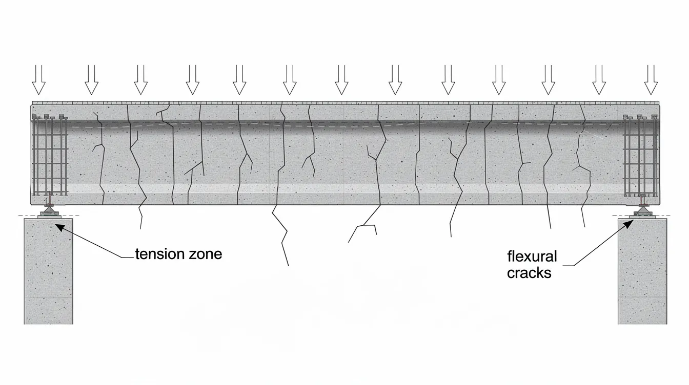
Structural deficiencies can arise from code changes or design errors, and empirical data establishes a baseline for structural modifications. During inspections, engineers may observe excessive deflection (visible sagging at midspan), flexural cracks on the beam soffit, diagonal shear cracks near supports, local spalling, or signs of reinforcement corrosion. However, visual signs alone are never a sufficient capacity check. Engineers must measure actual dimensions, map existing reinforcement using cover meters or radar scanning, assess concrete strength through core testing or non-destructive evaluation, and then perform a structural analysis against current codes to determine whether the beam’s load-bearing capacity remains adequate.
Section Enlargement as a Structural Strengthening Concept
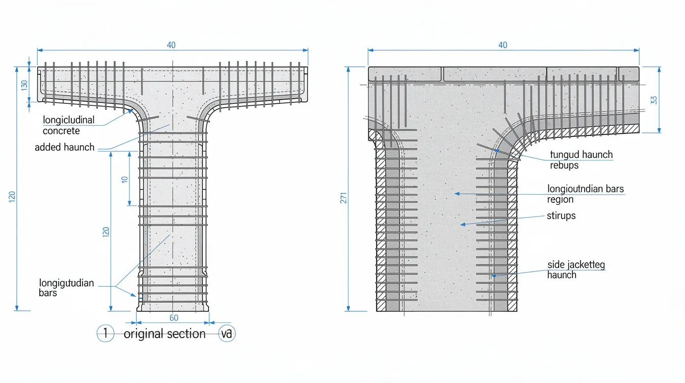
Section enlargement-also referred to as concrete jacketing-is a traditional retrofitting technique for overloaded concrete beams, and these concrete jacketing methods were developed as established strengthening techniques for upgrading existing beams. It involves adding new reinforced concrete to one or more faces of an existing beam so that the enlarged cross section carries the required loads as a unified composite system. New longitudinal bars and stirrups are positioned around the original beam during retrofitting, and shear connectors or dowels are installed to tie the old and new concrete together. Section enlargement increases load-carrying capacity and stiffness by enlarging the effective depth, width, or both of the beam.
The mechanics are straightforward: increasing beam depth significantly raises the moment capacity because the internal lever arm between the compression zone and the tension reinforcement grows, and the tensile strength of the reinforcement also contributes to how the enlarged section resists bending. Similarly, widening the beam web boosts shear capacity, which correlates with both web width and effective depth. Stiffness improves because moment of inertia increases with the cube of depth, which in turn significantly reduces deflection and helps control crack width under service loads.
Where does section enlargement sit relative to other methods? Fiber reinforced polymer composites, steel plates, near surface mounted reinforcement, and external post tensioning each offer alternatives with smaller geometric profiles. However, concrete jacketing provides more predictable long-term performance, inherent fire resistance, and well-understood behaviour under current building codes-qualities that are particularly valued in Singapore’s regulatory environment.
The key technical challenge is achieving reliable bond strength and load transfer at the interface between existing concrete and new concrete. Without aggressive surface preparation, adequately spaced mechanical dowels, and proper curing, the interface can become the weakest link. This challenge-and how to address it-runs through every strategy discussed below.
Design and Regulatory Context in Singapore and ASEAN
Structural strengthening works in Singapore are governed by SS EN 1992-1-1 (Eurocode 2 with the Singapore National Annex), supplemented by BCA-published design guides and local practice standards. For regional projects, ACI 318 or local codes may apply. Regardless of the standard, the design team must verify that the strengthened beam-and the entire load path from slab to column to foundation-satisfies ultimate limit state, serviceability, durability, and fire resistance requirements.
Key regulatory touchpoints include:
-
BCA structural submission: Detailed structural plans, calculation summaries, as-built drawings, and reinforcement schedules must be submitted via a Qualified Person. A complete guide to BCA submissions outlines the typical documentation and approval workflow.
-
SCDF fire safety: If section enlargement alters concrete cover or exposes reinforcement, fire rating compliance must be verified and may require a separate SCDF submission.
-
Interface shear design: EN 1992-1-1 clause 6.2.5 specifies that interface reinforcement is required when new concrete is cast against existing concrete. Straight bars crossing the interface must be embedded for at least 8 times the bar diameter, and spacing across the interface in the shear transfer direction must not exceed 2.5 times the section depth or 300 mm, whichever is smaller.
-
Concrete cover: Singapore standards require a minimum cover of 35 mm on all faces for beam main reinforcement; any change to cover from enlargement must maintain or exceed this for both durability and fire resistance.
At AMAN Engineering Consultancy, we integrate condition assessment, 3D structural modelling, BCA application document preparation, and liaison with BCA and SCDF to ensure that strengthening designs move through approval efficiently. Understanding the common section enlargement configurations-covered next-helps project teams evaluate feasibility before committing to detailed analysis.
Common Section Enlargement Strategies for Overloaded Concrete Beams
There is no one-size-fits-all solution for strengthening overloaded beams. The right configuration depends on the nature of the structural deficiency (flexural, shear, or both), available headroom, proximity of M&E services, fire rating requirements, construction access, and cost. Typical enlargement is 3–5 inches (75–125 mm) for beams, though specific dimensions are always driven by calculation.
This section presents the four most widely used strategies, each with typical use cases, advantages, limitations, and constructability notes.
Bottom Flange Deepening (Adding a Haunch Below the Beam)
Bottom flange deepening adds a reinforced concrete haunch beneath the beam soffit, increasing the effective depth and dramatically boosting flexural capacity. The new concrete contains longitudinal tension bars anchored into the existing beam via epoxy-grouted drilled dowels, along with stirrups that tie the new haunch to the original beam. Mechanical dowels ensure composite action in section enlargement, preventing interface slip between old and new materials.
When to use it: This strategy is most effective when bending governs the design-typically at midspan-and when clear height below the beam permits the added depth. Plant rooms, basement carparks, and industrial spaces with generous storey heights are ideal candidates.
Reinforcement concepts: New longitudinal bars are placed at the bottom of the haunch to maximise the lever arm. These bars must be anchored into the beam near supports with sufficient development length per SS EN 1992. Stirrups in the haunch extend upward into the existing beam via drilled dowels spaced per interface shear requirements. A rule-of-thumb estimate: adding 150–200 mm of depth to a beam can increase flexural capacity by 25–50%, depending on the original section geometry.
Advantages:
-
Significant gain in flexural capacity and stiffness
-
Relatively simple bar layout and formwork (single soffit panel)
-
Does not encroach into the usable width of the space
Limitations:
-
Reduces headroom below the beam, which may conflict with minimum ceiling height requirements or M&E duct routes
-
Added dead load increases support reactions, potentially requiring evaluation of concrete columns and foundations
-
Surface finish below the beam must be reinstated, including any fire protection or architectural treatment
Side Jacketing and Beam Widening
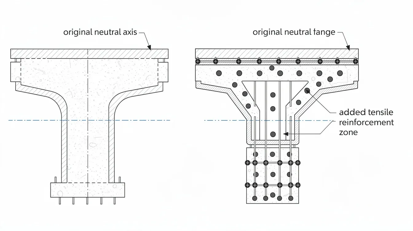
Side jacketing adds reinforced concrete to one or both sides of the beam web, increasing width and thereby improving shear capacity. In some configurations, additional longitudinal bars placed in the side jackets also enhance flexural capacity. Transverse dowels drilled through the existing beam web connect old and new concrete, mobilising shear transfer across the interface.
When to use it: Side jacketing is preferred when headroom is constrained but lateral space is available-for example, beams adjacent to non-structural partitions that can be relocated, or beams in open carpark structures where minor width increases are acceptable. It is particularly effective when shear deficiency near supports is the governing concern.
Reinforcement concepts: Longitudinal bars run along the sides of the jacket, with stirrups wrapping around both the new and existing beam sections. Dowels spaced at no more than 300 mm cross the interface to maintain composite action per EN 1992-1-1 requirements. Aggressive surface preparation-scabbling or sandblasting-is needed for effective bonding on vertical surfaces where gravity works against adhesion.
Advantages:
-
Preserves headroom, avoiding conflicts with ceiling heights and floor-to-floor clearances
-
Improves shear resistance and, when combined with additional longitudinal steel, flexural capacity
-
Integrates well with fireproofing boards or spray-applied fire protection on beam sides
Drawbacks:
-
Encroaches into usable floor width, which may conflict with adjoining architectural elements, M&E risers, or lease line dimensions
-
Formwork on vertical faces can be more complex, especially in congested ceiling zones
-
Interface bond on sides is more sensitive to construction quality than soffit interfaces
Full U-Jacketing (Bottom and Sides) for Combined Flexural and Shear Strengthening
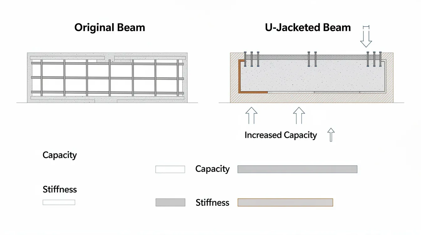
Full U-jacketing simultaneously enlarges the beam soffit and both sides so that the new concrete wraps around three faces of the existing beam. This approach delivers the most significant gains in both flexural and shear capacity, making it the go-to method for heavily overloaded beams where both failure modes must be addressed.
When to use it: U-jacketing is typically adopted when converting structures built in the 1990s or early 2000s to substantially heavier uses-such as retail podiums becoming logistics hubs or data centres-where both increased bending moments and higher shear forces act on the same beams. Research by Dong et al. (2012) tested beams enlarged from a 150 × 200 mm section to 250 × 300 mm, demonstrating shear capacity gains exceeding 50% and improved ductility when interface connectors and stirrups were properly provided.
Reinforcement detailing: Continuous stirrups are formed within the new jacket wrapping the base and both sides, tied into the existing beam via drilled dowels. Longitudinal bars are placed at optimal lever-arm positions in the haunch and sides. High-performance concrete is used to minimize shrinkage cracking during curing and to ensure material properties compatible with the existing concrete.
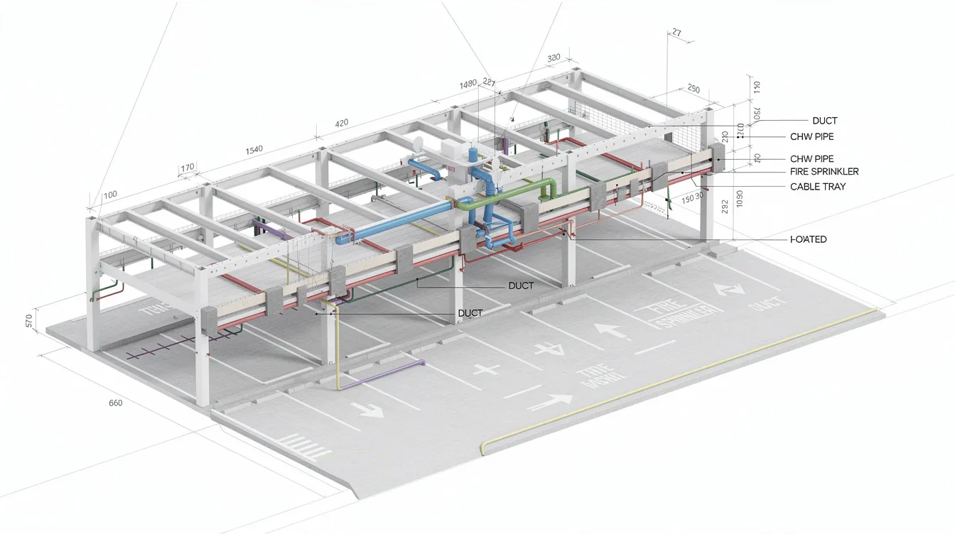
Constructability issues: Construction of section enlargement can be disruptive due to extensive formwork requirements on three faces. Temporary support is often required to relieve service loads before retrofitting. Works must be staged carefully-often bay by bay-to keep parts of the building operational. Access for formwork and concreting in congested ceiling zones with ducts, sprinklers, and cable trays demands early BIM coordination.
Localised Support Zone Enlargement (Beam-Column Joint and Bearing Regions)
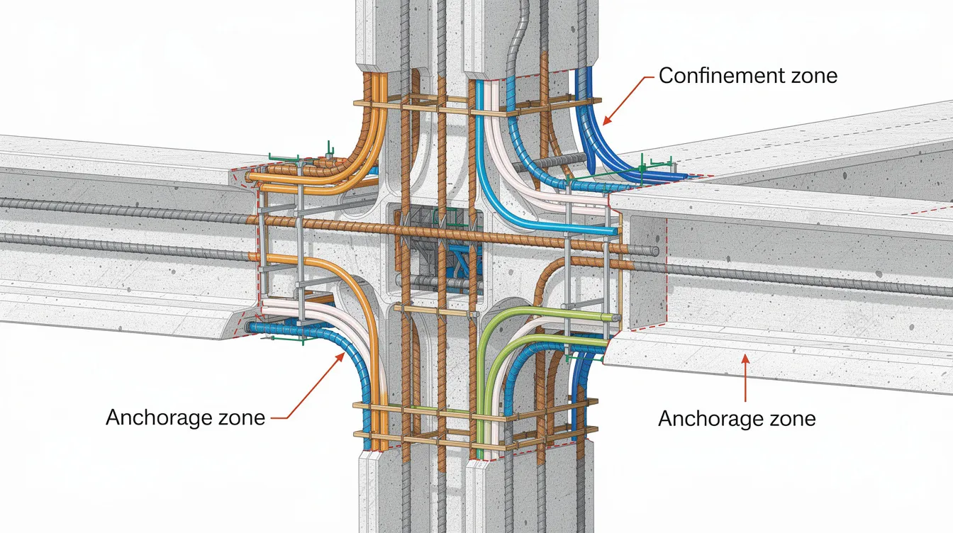
Rather than enlarging the full span, localised support zone enlargement targets the high-stress regions near columns and supports where shear demand and joint forces are concentrated. This approach thickens beam ends, adds haunches at columns, or enlarges the beam-column joint core itself.
When to use it: Detailed structural analysis sometimes reveals that mid-span flexural capacity is adequate but that shear or joint capacity near supports is deficient-particularly in older frames with limited shear reinforcement or poor joint detailing. Structural assessments identify deficiencies from environmental effects such as reinforcement corrosion at joints where water ingress is common.
Reinforcement concepts: Additional stirrups and hoops are installed around the joint, with dowelled longitudinal bars distributing bending moment across the interface. Confinement reinforcement is critical to prevent brittle failure at these highly stressed regions.
Advantages:
-
Concentrates materials and disruption to the areas where strengthening is actually needed
-
Reduces concrete volume and cost compared to full-span jacketing
-
Limits headroom loss to localised zones rather than the entire beam length
Limitations:
-
Requires accurate modelling to identify critical zones and avoid stress concentrations at the transition between enlarged and original sections
-
High shear forces at enlarged supports may transfer increased reactions into columns, potentially triggering the need for column jacketing
-
Formwork and access around column faces can be challenging, particularly in corner joints
From Concept to Construction: Implementing Section Enlargement
Once a section enlargement strategy is chosen, the project moves through a disciplined process from assessment to design to construction. Each phase has distinct deliverables, coordination requirements, and quality checkpoints. AMAN Engineering Consultancy integrates structural assessment, BIM modelling, authority submissions, and site coordination to keep projects on track.
Assessment and Option Study Workflow
A structural assessment should be initiated whenever a change-of-use proposal is under consideration, during due diligence before property acquisition, when recurring serviceability issues appear (excessive deflection, cracking), or when new equipment loads are being planned. Structural assessments are essential for extending asset lifespans and for establishing the baseline data needed for any strengthening design.
The typical workflow follows these steps:
-
Review of original drawings and past alterations – Compile as-built structural drawings, previous renovation records, and construction documentation to understand the existing structure.
-
On-site structural inspection – Measure beam dimensions, map existing reinforcement using cover meters or ground-penetrating radar, and record visible damage. A structural engineer inspection documents cracking patterns, spalling, deflection, and signs of reinforcement corrosion.
-
Non-destructive testing and material sampling – Rebound hammer tests, ultrasonic pulse velocity measurements, and core sampling for compressive strength testing establish the material properties of the existing concrete.
-
Analytical modelling – Build a frame or 3D finite-element model encompassing beams, slabs, concrete columns, and foundations. Load testing verifies a structure’s capacity to support design loads where analytical results require validation.
-
Capacity check against new loadings – Compare calculated capacity (flexure, shear, deflection, crack width) with proposed new load combinations to quantify the shortfall.
-
Development of strengthening options – For each deficient beam or beam group, sketch several section enlargement strategies alongside alternatives, estimating cost, headroom impact, programme, and authority compliance.
AMAN uses 4D BIM planning and Tekla 3D models to visualise clashes between enlarged beams and services, simulate construction stages, and produce reinforcement shop drawings directly from the model. Deliverables to clients include a capacity assessment report, schematic strengthening proposals with pros and cons, and preliminary cost and programme estimates.
Detailed Design and Coordination with Authorities
Key design checks for the enlarged beam include ultimate limit state verification (flexure, shear, torsion), serviceability assessment (deflection under service loads, crack width limits per SS EN 1992), durability (concrete grade, minimum cover), and fire rating compliance. The design must also evaluate global frame behaviour-because added dead load from enlargement shifts reactions to columns and foundations, the entire load path must be verified.
Design documentation includes enlarged cross sections with rebar schedules, interface detailing (dowel diameter, spacing, embedment length), temporary propping layouts, and construction stage notes. All documentation is coordinated within BIM models so that structural, M&E, and architectural information remains synchronised.
Authority submission in Singapore typically involves:
-
BCA structural submission via a Qualified Person, including structural plans, reinforcement schedules, and calculation summaries demonstrating compliance with SS EN 1992
-
SCDF fire safety review if the enlargement changes cover dimensions, exposes previously protected reinforcement, or alters the fire rating of the beam
-
Coordination with URA, JTC, or LTA for specialised properties, conservation buildings, or infrastructure assets
AMAN manages these submissions end-to-end, resolving technical queries on strengthening assumptions and ensuring that BCA application documents are complete before filing.
Comparison: As-Is Beam vs. After Section Enlargement
|
Parameter |
As-Is Beam |
After Section Enlargement |
|---|---|---|
|
Beam depth |
400 mm |
550–600 mm (with haunch) |
|
Web width |
300 mm |
400–500 mm (with side jackets) |
|
Flexural capacity |
Original design value |
25–80% increase (project-specific) |
|
Shear capacity |
Original design value |
30–50%+ increase (with added stirrups) |
|
Midspan deflection |
May exceed L/250 limit |
Brought within code limits |
|
Fire rating |
Per original cover |
Maintained or improved with new cover ≥ 35 mm |
Construction Sequence for Beam Section Enlargement
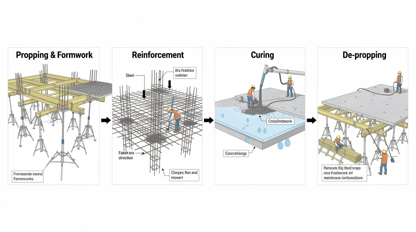
Sequencing is critical to avoid overloading the existing structure during works and to ensure proper bond and curing. Temporary support is often required to relieve service loads before retrofitting, and props must be designed so that they do not overstress adjacent members or slabs.
A typical construction sequence proceeds as follows:
-
Temporary propping and partial unloading – Install adjustable steel props beneath the beam span and supported slabs. Props remain in place until the new concrete achieves adequate compressive strength (typically 70–80% of design strength).
-
Removal of finishes and surface preparation – Strip existing ceiling finishes, fireproofing, and loose concrete. Roughen the concrete surface via scabbling, bush hammering, or hydro-demolition to expose aggregate and achieve the target roughness profile. A 2024 study on interface shear performance confirmed that rough surface preparation significantly enhances interface shear transfer, while smoother interfaces suffered significant slip and delamination under load.
-
Installation of dowels and shear connectors – Drill into the existing beam at specified centres using templates that avoid cutting existing reinforcement. Install epoxy-grouted dowels or mechanical anchors per design spacing and embedment requirements. Pull-off tests on sample installations may be required for quality assurance.
-
Placement of new reinforcement – Position new longitudinal bars and stirrups around the original beam, ensuring adequate lap lengths, clear cover (≥ 35 mm), and connection to existing reinforcement via the installed dowels.
-
Formwork and interface treatment – Erect formwork panels (soffit, sides, or U-shape depending on the strategy). Apply bonding agents or cementitious slurries to the prepared concrete surface immediately before casting.
-
Concreting, vibration, and curing – Cast using a suitable concrete mix-often C40/50 or higher for strengthening works. Vibrate thoroughly to ensure consolidation, especially in narrow jacket sections. Curing is essential to verify the composite action of newly added materials; wet hessian or curing compounds are maintained for a minimum period per specification.
-
Formwork removal and de-propping – Remove formwork only after concrete strength tests (cubes or cylinders) confirm adequate strength. De-prop gradually as specified in the method statement.
-
Reinstatement and gradual reloading – Reinstate finishes, fire protection, M&E services, and architectural elements. Reload progressively, including any required load testing to verify performance.
Quality control checkpoints include verification of dowel installation depth, reinforcement positioning and cover, concrete strength at de-propping, and visual inspection for interface cracking under initial loading.
Integration with BIM, M&E, and Architectural Design
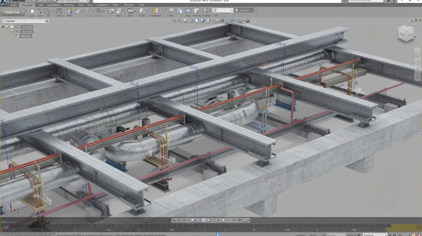
Section enlargement inevitably interacts with ceiling systems, duct runs, cable trays, sprinkler piping, and architectural finishes. An enlarged beam that reduces headroom by 150 mm can render an entire floor non-compliant with minimum ceiling height requirements or force expensive rerouting of M&E systems.
AMAN’s BIM-based approach addresses this through early clash detection between enlarged beam profiles and existing services. Coordinated 3D models allow the design team to identify conflicts before finalising strengthening details, produce shop drawings that show both structural reinforcement and service relocations, and generate clear 3D visualisations for contractors and building managers.
Fire rating must be maintained or improved: new concrete surfaces require adequate cover, and any penetrations through enlarged beams need fire stopping details coordinated with SCDF requirements. These details are embedded in the BIM model and included in authority submissions.
Comparing Section Enlargement with Alternative Strengthening Methods
While section enlargement is robust and well understood by contractors in Singapore, it is not always the optimal choice. Alternative strengthening techniques-including fiber reinforced polymer composites, steel plate bonding, steel jacketing, and external post tensioning-may perform better in specific contexts. This comparison helps project teams determine when section enlargement is truly the best solution.
Technical and Practical Trade-Offs
|
Criterion |
Section Enlargement |
FRP / Composite Strengthening |
Steel Plate / External PT |
|---|---|---|---|
|
Added dead load |
High (75–125 mm of new concrete per face) |
Very low |
Low to moderate |
|
Headroom impact |
Significant (bottom deepening) to moderate (side jacketing) |
Minimal (1–3 mm thickness) |
Moderate (steel plates or tendons) |
|
Fire performance |
Inherent fire resistance from concrete cover |
Poor unless separately fire-protected |
Steel requires fire-protection coating |
|
Durability in tropical climate |
Excellent with proper concrete design |
UV and moisture sensitivity; requires maintenance |
Corrosion risk unless protected |
|
Construction speed |
Slower (curing time, formwork) |
Faster installation |
Moderate |
|
Capacity increase potential |
Very high (20–80%+ flexural, 30–50%+ shear) |
Moderate to high for flexure; limited for shear |
High for flexure; variable for shear |
|
Code familiarity in Singapore |
Well established under SS EN 1992 |
Evolving; requires specialist detailing |
Well established but less common for beams |
Section enlargement adds significant dead weight but offers major capacity increases, robust behaviour, and inherent fire resistance. It is the preferred method when long-term durability, fire rating, and large capacity gains are priorities.
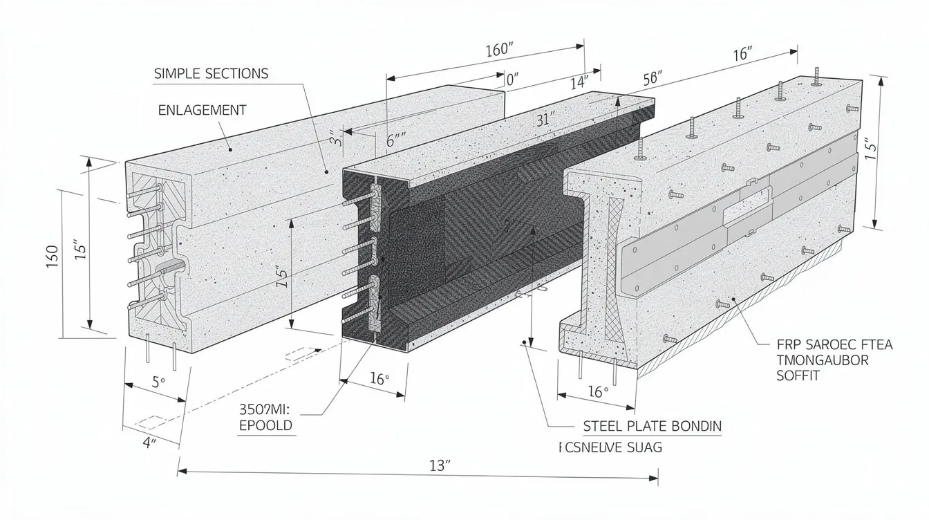
CFRP systems can enhance structural capacity without adding significant weight, making fiber reinforced polymer an attractive option for lightly overloaded beams where fire protection can be separately addressed. Steel plate bonding enhances flexural and shear capacity in concrete members but is susceptible to corrosion in Singapore’s humid climate unless rigorously protected. External post-tensioning applies active forces to resist new loads but requires specialised anchorages, access for tendon routing, and ongoing inspection. Span shortening reduces span length by adding supports underneath members-an approach that avoids modifying the beam itself but introduces new columns and foundations.
Cost, Programme, and Operational Considerations
Cost drivers for section enlargement include the volume of new concrete and reinforcement, extent of temporary propping, access constraints (scaffold versus mobile platforms), the need for night works to avoid disrupting daytime operations, and phasing strategy. Authority submission fees and any fire safety upgrades add to the total.
For a mid-sized project-strengthening 20–30 beams on a single floor of a commercial building-the construction phase might span 3–6 months depending on phasing and occupation constraints. Section enlargement can be staged bay by bay or column line by column line to limit downtime, though each bay requires its own curing period before props can be removed.
By contrast, FRP installation is faster per beam but carries higher material costs and may not deliver sufficient capacity for heavily overloaded members. The choice often comes down to the combination of required capacity uplift, fire and durability performance, programme pressure, and budget-factors that the design team must evaluate holistically for each project.
Common Challenges and How to Avoid Them
Many issues with section enlargement arise from poor preparation of the existing concrete, inadequate interface design, or incomplete system-level checks. Recognising these pitfalls early-and applying proven countermeasures-separates successful projects from costly remedial works.
Poor Bond Between Old and New Concrete
The interface between existing concrete and new concrete is often the critical failure plane. Without adequate roughness, closely spaced connectors, and clean surfaces, shear slip or delamination can occur, leading to brittle failure rather than the intended composite behaviour.
Solutions: Specify aggressive surface preparation to a defined roughness profile (e.g. 3–5 mm exposed aggregate depth via scabbling or hydro-demolition). Install dowels or shear keys at spacing no greater than 300 mm per EN 1992-1-1. Apply bonding agents or cementitious slurry immediately before casting. Conduct pull-off or shear tests on trial panels before full-scale production to verify bond strength. Photograph every prepared surface before formwork closure for quality records.
Underestimating Global Structural Effects
Strengthening beams locally without checking the rest of the existing structure can shift the “weak link” to columns, slabs, or foundations. The added dead load from enlargement increases support reactions-sometimes by 15–25%-which may exceed the capacity of concrete columns or pad footings.
Solutions: Perform a global structural analysis using frame or 3D models that incorporate the enlarged beam sections and their increased self-weight. Verify column capacity, foundation bearing pressure, and overall frame stability under all relevant load combinations. AMAN routinely performs such holistic checks as part of value engineering and authority submissions, ensuring that structural defects are rectified properly across the entire system.
Clashes with Services, Fire Stopping, and Architectural Elements
Enlarged beams frequently clash with HVAC ducts, fire sprinklers, lighting tracks, or ceiling heights specified in tenant leases. These conflicts, if discovered late, cause expensive rework and programme delays.
Solutions: Initiate BIM clash detection with M&E and architectural teams before finalising strengthening details. Model enlarged beam profiles in 3D alongside all services to identify conflicts early. Adjust fire stopping details around penetrations through enlarged beams and maintain fire compartmentation as required by SCDF. Involve the facility manager early to confirm that revised headroom and service routes are acceptable.
Construction Sequencing and Safety Risks
Removing props too early, overloading partially strengthened beams, or accidentally cutting existing reinforcement while drilling for dowels are among the most serious construction risks. Each can compromise structural integrity and endanger workers and occupants.
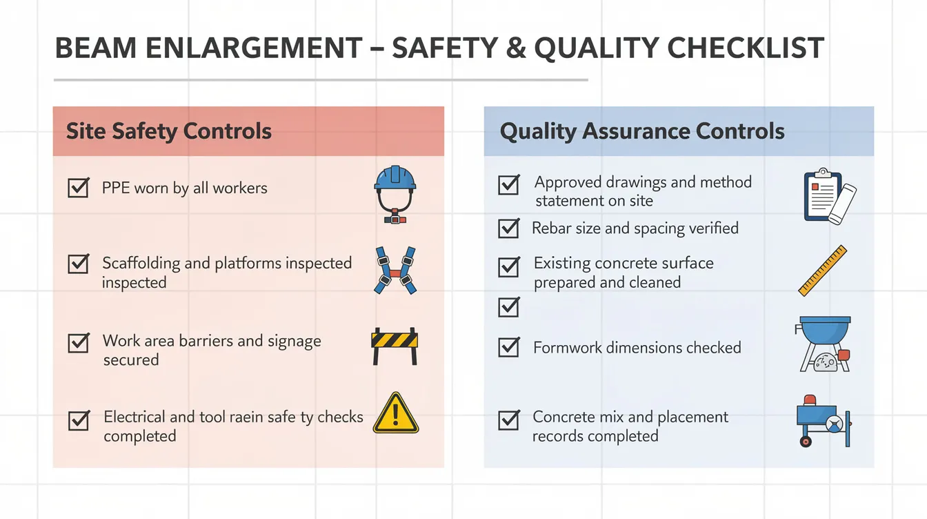
Solutions: Prepare detailed method statements specifying propping loads, sequence, and minimum concrete strength before de-propping. Use drilling templates and rebar locators to avoid cutting existing reinforcement. Require supervision by a Professional Engineer or appointed representative at all critical stages. Establish clear hold points-where work cannot proceed until inspection and sign-off are complete-for dowel installation, reinforcement placement, and concrete strength verification.
Conclusion and Next Steps
Section enlargement remains one of the most powerful and well-established approaches to strengthening overloaded concrete beams in existing buildings. By adding bonded reinforced concrete to the beam cross section-whether as a bottom haunch, side jacket, full U-jacket, or localised support zone upgrade-engineers can significantly enhance flexural and shear capacity, improve stiffness, and extend the building’s service life while maintaining structural integrity and compliance with current building codes.
The choice of strategy must be tailored to the specific structural demand, spatial constraints, fire requirements, and operational needs of each project. Equally important is the quality of evaluation, interface detailing, and construction execution-these determine whether the enlargement performs as a true composite system or becomes a maintenance liability.
Immediate next steps for readers considering strengthening:
-
Commission a structural assessment and beam capacity check to quantify the shortfall against current code requirements.
-
Engage an engineering consultancy like AMAN to develop options-including section enlargement-and to model the impact on the whole structure, columns, and foundations.
-
Coordinate early with architects, M&E engineers, and facility managers via BIM to identify clashes and maintain operational clearances.
-
Plan phasing, safety protocols, and authority submissions well before site mobilisation to avoid delays and cost overruns.
Related topics that readers may want to explore include column jacketing for overloaded vertical members, slab strengthening for increased floor loads, façade rectification works, and fire safety upgrades-all areas where AMAN provides integrated structural and consultancy support.
Additional Resources and How AMAN Engineering Consultancy Can Help
For readers looking to deepen their understanding or initiate a strengthening project, the following resources are valuable:
-
Key standards: SS EN 1992-1-1 (Eurocode 2) clauses on interface shear transfer (clause 6.2.5) and composite sections; BCA Building Control Regulations for submission requirements; ACES Design Guide for Headed Bar to Eurocode 2 (July 2024) for modern anchorage detailing in Singapore.
-
Industry case references: URA’s Conservation Technical Handbook Volume 4 (Structure) includes examples of beam strengthening via section enlargement in heritage buildings.
-
AMAN services: Periodic structural inspection, forensic engineering, BIM modelling, authority submissions, and value engineering for structural strengthening projects.
AMAN Engineering Consultancy supports the full lifecycle of a strengthening project-from diagnostic surveys and concrete spalling assessment to 3D modelling, design, authority approval, and site support. If you are evaluating overloaded beams in an existing building or planning a change-of-use conversion, contact AMAN for project-specific advice tailored to Singapore’s regulatory and construction environment.
Frequently Asked Questions on Section Enlargement for Overloaded Beams
This FAQ addresses common queries that owners, architects, and project managers raise during early-stage discussions about beam strengthening.
When is section enlargement preferable to demolishing and recasting beams?
Section enlargement is generally preferable when the existing structure is sound overall, access for full demolition is limited, tenants need to remain in place during works, or heritage or conservation constraints apply. It avoids the cost, disruption, and environmental impact of demolishing and replacing entire beams. Full replacement may be more suitable when there is extensive reinforcement corrosion, poor original detailing that cannot be relied upon, or when major geometric changes to the structure are needed that go beyond what enlargement can achieve.
How much additional load capacity can section enlargement typically provide?
Gains depend on the original beam geometry, the extent of enlargement, and the reinforcement provided. In practice, 20–80% increases in flexural capacity are common when the enlargement is adequately designed. Experimental studies have demonstrated shear capacity gains exceeding 50% for beams enlarged in both width and depth with proper interface connectors and stirrups. However, every project requires specific structural analysis and code checks-generic rules of thumb should not substitute for calculation by a qualified engineer.
Will section enlargement significantly increase the building’s dead load?
Yes. Added concrete increases the beam’s self-weight, and this additional dead load must be checked against column and foundation capacities. As a high-level example, enlarging a 300 mm wide beam by adding a 150 mm deep haunch over a 7 m span adds approximately 2.5–3.0 kN of extra dead load per beam-a meaningful increase that propagates through the structural system. The design team must verify global effects, not just local beam capacity.
Can section enlargement be done while the building remains operational?
In many commercial and industrial buildings in Singapore, works are staged by zone-often during night shifts or over weekends-with temporary propping and safety barriers separating work areas from occupied zones. This allows partial operation to continue. Success depends on careful planning, clear communication with occupants and building management, and coordination with SCDF and BCA regarding safety during construction. A periodic structural inspection before and after works provides documented assurance that the building remains safe throughout.
How long does a typical beam section enlargement project take?
A small project strengthening 10–15 beams on a single floor might take 4–8 weeks from site mobilisation to de-propping, depending on curing times, concrete strength gain rates, and the phasing strategy adopted. Larger multi-storey projects can extend over several months but are typically sequenced bay by bay to limit disruption. Programme duration is influenced by the number of beams, access conditions, whether night works are required, and the time needed for authority approvals and materials procurement.