
The Insidious Nature of Marine Infrastructure Deterioration and the Imperative for Proactive Non destructive Diagnostics
The deterioration of reinforced concrete structures situated within highly aggressive, chloride-laden marine environments represents one of the most formidable and financially demanding challenges encountered within the expansive domain of modern civil infrastructure engineering, necessitating the continuous deployment of advanced diagnostic methodologies that decisively transcend the profound limitations of traditional visual inspections.
The fundamental limitation inherent in conventional visual inspection methodologies is their complete and uncompromising reliance upon the physical manifestation of structural damage—such as overt concrete spalling, extensive surface delamination, or the prominent excretion of reddish-brown rust stains—which unequivocally indicates that the structural element has already surpassed its critical serviceability thresholds and requires immediate, exceptionally costly interventions.
Because the localized oxidation of embedded reinforcing steel generates expansive solid corrosion by-products that exert immense outward tensile stresses on the surrounding brittle concrete matrix, the prolonged period preceding actual physical failure is entirely characterized by invisible, electrochemical degradation occurring deep beneath the opaque surface of the structural element4.
Consequently, identifying and precisely quantifying this active electrochemical corrosion during its nascent, preclinical stages, long before visible cracking or aggressive spalling appears on the exterior concrete surface, is absolutely imperative for optimizing targeted remediation expenditures and preventing catastrophic structural failures across aging bridge decks, coastal seawalls, and deep-water port facilities2.
Within the highly specialized and constantly evolving discipline of nondestructive testing and evaluation, Half-Cell Potential (HCP) mapping has undeniably emerged as the foremost, globally standardized electrochemical technique designed specifically to evaluate the underlying thermodynamic probability of active corrosion occurring within embedded steel reinforcement networks1.
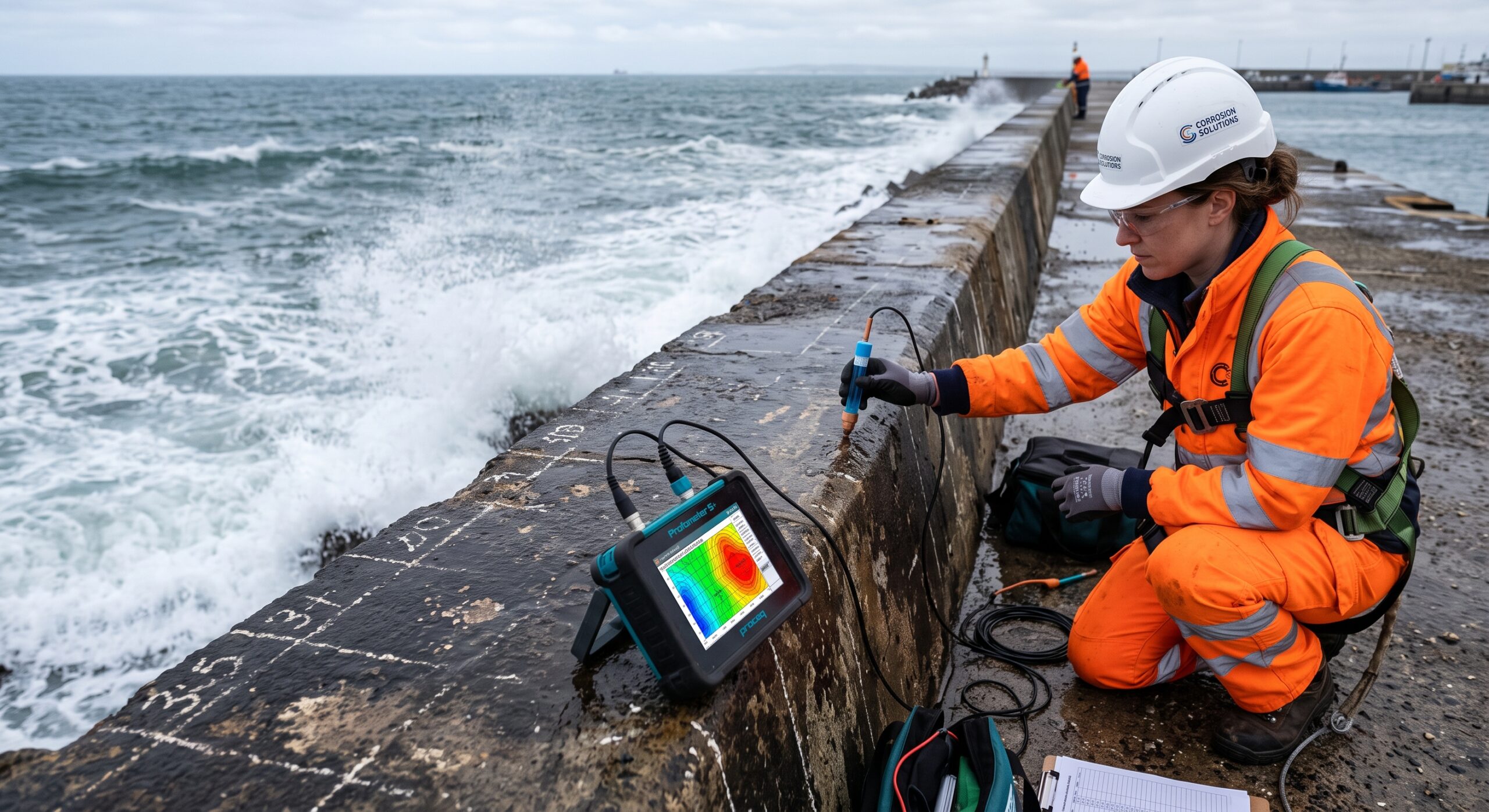
By meticulously measuring the minute electrical potential difference existing between a highly stable, standardized reference electrode placed directly upon the exterior concrete surface and the embedded steel reinforcement network situated beneath it, structural asset managers and diagnostic engineers can mathematically construct exceptionally high-resolution topographical contour maps that vividly illustrate subsurface corrosion activity in real-time2.
This sophisticated electrochemical technique fundamentally transforms the dense concrete matrix from an entirely opaque physical barrier into a diagnostically transparent medium, allowing engineers to mathematically delineate precise geometric regions of active deterioration, successfully target highly specific locations for subsequent destructive chloride profiling, and confidently design optimized, cost-effective remediation strategies that directly address the root electrochemical cause of the structural pathology rather than merely temporarily repairing its superficial, symptomatic cracking1.
Electrochemical Thermodynamics: The Genesis of Chloride-Induced Macrocell Corrosion
To fully comprehend the diagnostic capabilities and the underlying physical mechanisms governing half-cell potential mapping, it is first absolutely necessary to thoroughly examine the complex thermodynamic interactions and kinetic mechanisms that exclusively control the corrosion of carbon steel when it is deeply embedded within a highly alkaline, porous cementitious matrix.
Under normal, non-aggressive atmospheric conditions, the fundamental hydration process of Portland cement naturally generates a highly alkaline aqueous pore solution—typically maintaining an elevated pH ranging strictly between 12.5 and 13.5—which spontaneously facilitates the rapid formation of an extraordinarily thin, exceptionally dense, and tightly adhering microscopic layer of gamma ferric oxide () directly upon the exterior surface of the reinforcing steel bars4.
This microscopic protective barrier, which is universally referred to throughout metallurgical engineering literature as the passive oxide film, effectively and completely isolates the underlying vulnerable metallic iron from the surrounding reactive aqueous environment, thereby reducing the localized rate of electrochemical dissolution to virtually negligible background levels and guaranteeing the long-term structural durability of the steel reinforcement4.
However, when aging reinforced concrete structures are continuously and relentlessly exposed to highly aggressive marine environments that are densely characterized by continuous saltwater splashing, dramatic tidal fluctuations, or pervasive airborne chloride salt spray, aggressive negative chloride ions inevitably diffuse inward through the interconnected microscopic capillary pore network of the protective concrete cover over extended temporal periods1.
Once the accumulated concentration of these aggressively penetrating chloride ions at the exact physical depth of the reinforcing steel reaches a critically defined thermodynamic threshold, they systematically and aggressively catalyze the localized destabilization and subsequent rapid dissolution of the protective passive film, thereby initiating a highly destructive and localized phenomenon known universally within the corrosion sciences as pitting corrosion1.
The sudden localized destruction of this protective barrier creates a massive inherent thermodynamic instability across the contiguous surface of the steel reinforcement, directly leading to the spontaneous formation of a highly localized electrochemical macrocell that is physically characterized by distinct, widely separated anodic and cathodic regions4.
At the newly formed localized anodic sites, where the passivating oxide film has been completely compromised by the concentrated chlorides, the exposed metallic iron undergoes continuous active oxidation, rapidly releasing dissolved positive ferrous ions into the surrounding alkaline pore solution while simultaneously surrendering surplus negatively charged electrons into the conductive solid steel matrix, a fundamental reaction that is mathematically expressed by the equation 4.
Concurrently, at the adjacent extended cathodic sites where the protective passive film fortunately remains structurally intact, the surplus electrons transported laterally through the highly conductive steel matrix are systematically consumed through the complex electrochemical reduction of dissolved atmospheric oxygen and liquid water, subsequently generating highly alkaline hydroxyl ions according to the corresponding chemical equation 4.
The continuous and necessary spatial separation of these highly localized anodic oxidation reactions and the corresponding widespread cathodic reduction reactions across the surface of the reinforcing steel creates a distinctly measurable electrical potential difference, subsequently generating a continuous flow of ionic current traversing outward through the moisture-laden concrete electrolyte and a corresponding electron current flowing laterally through the continuous metallic steel rebar network4.
It is precisely this naturally generated electrochemical potential gradient, forcefully radiating outward from the actively corroding subsurface anodic sites and propagating longitudinally and transversely through the surrounding electrically resistive concrete matrix to the easily accessible structural surface, that provides the fundamental physical and mathematical basis for all half-cell potential mapping measurements4.
By systematically traversing the structure and mapping these minute variations in surface voltage using highly specialized diagnostic instrumentation, structural diagnosticians can precisely locate the invisible, highly active anodic sites where the severe dissolution of the structural steel cross-section is occurring at a structurally threatening, accelerated rate4.
The Physics and Instrumentation of High-Resolution Equipotential Mapping
The fundamental operating principle governing all half-cell potential testing methodologies essentially involves the deliberate and highly controlled creation of a temporary closed electrical measurement circuit that elegantly and effectively bridges the significant physical gap existing between the internal metallic reinforcement network and the external concrete surface by utilizing a highly specialized, standardized thermodynamic reference electrode1.
Because the absolute electrical potential of a single isolated electrode fundamentally cannot be measured directly in complete isolation without closing a circuit, the thermodynamic state of the embedded steel must be comparatively evaluated against a universally recognized reference electrode that reliably maintains a strictly constant, thermodynamically reversible half-cell potential under all reasonably anticipated typical field testing conditions2.
For the vast and overwhelming majority of reinforced concrete diagnostic assessments that are rigorously conducted in strict accordance with international testing protocols, structural engineers preferentially employ a copper/copper sulfate electrode (CSE), which typically consists of a highly purified, solid copper rod that is continuously submerged within a chemically saturated, highly conductive aqueous solution of copper sulfate, typically contained within a transparent, non-conductive polymeric tube featuring a precisely engineered porous ceramic or wooden plug situated at its base to facilitate essential electrolytic ionic contact with the wetted concrete surface2.
To successfully execute this delicate diagnostic procedure in the field and accurately capture the exceedingly minute potential differences generated by deeply buried subsurface macrocell activity without distorting the data, the utilization of a specialized high-impedance digital voltmeter is strictly and unequivocally required by all governing international standards2.
The integration of a sophisticated high-impedance measurement device—which typically features an internal electrical resistance far exceeding ten to one hundred megaohms—is an absolute physical necessity for the procedure, as it explicitly guarantees that virtually zero electrical current is inadvertently drawn from the highly sensitive concrete-rebar macrocell during the brief period of active measurement, thereby effectively preventing any artificial polarization of the electrodes that would inevitably and disastrously distort the true reversible equilibrium potential of the actively corroding structural system2.
The negative electrical terminal of this highly sensitive diagnostic voltmeter is physically and mechanically connected directly to the embedded reinforcing steel network through a locally excavated and meticulously cleaned connection point, while the corresponding positive terminal is seamlessly connected via an insulated wire to the mobile reference electrode that systematically traverses the pre-wetted exterior surface of the structural concrete element4.
The dense concrete matrix itself, deeply permeated by an alkaline pore solution that is highly saturated with various dissolved ionic species, functions dynamically as the electrolytic salt bridge that ultimately and necessary completes this complex macroscale electrochemical diagnostic circuit1.
When the standardized copper/copper sulfate reference electrode is systematically positioned at predetermined, carefully measured nodes situated across a carefully demarcated geometric grid spacing upon the external concrete surface, the high-impedance voltmeter precisely quantifies the electrical potential difference—commonly referred to within the industry simply as the voltage—existing between the thermodynamically stable reference half-cell and the highly variable, unknown steel reinforcement half-cell located deep within the structure2.
Because actively corroding anodic regions of the embedded steel inherently possess a substantially higher thermodynamic tendency to oxidize and spontaneously release electrons into the matrix, these actively deteriorating localized sections consistently exhibit significantly more negative electrical potential values when they are comparatively measured against the constant standardized copper/copper sulfate reference electrode situated on the surface3. Modern diagnostic equipment explicitly engineered for these advanced surveys, such as the highly sophisticated CorroMap platform or the renowned PM8500 Profometer Corrosion meter, dramatically streamline this data collection process by automatically recording the stabilized voltage readings at each grid node and dynamically rendering preliminary equipotential contour maps directly on the device’s display screen during active field testing1.
Strict Compliance with Standardized Methodologies: The ASTM C876 Protocol
The successful extraction of highly reliable, diagnostically actionable, and legally defensible half-cell potential data from complex, heavily weathered marine structures mandates strict, unwavering adherence to standardized methodological protocols, the most universally recognized and widely adopted of which is formally designated by the American Society for Testing and Materials as ASTM C876: Standard Test Method for Corrosion Potentials of Uncoated Reinforcing Steel in Concrete4.
The exceptionally rigorous diagnostic procedure meticulously delineated within this comprehensive international standard ensures that the countless complex environmental and physical variables capable of heavily influencing delicate electrochemical measurements are systematically controlled and normalized, thereby definitively facilitating highly accurate comparative analysis across vastly different structural elements and enabling reliable, prolonged temporal monitoring periods extending over several decades2.
The initial preparatory phase of a meticulously executed field investigation necessarily mandates a comprehensive visual inspection intended to identify obvious external morphological anomalies and to appropriately define the optimal spatial resolution of the required measurement grid, which is typically established at standardized intervals of approximately 300 millimeters to 500 millimeters, depending entirely upon the geometric complexity of the specific structural member under evaluation and the requisite resolution of the resultant topographical potential map2.
Once the comprehensive geometric grid layout is definitively established across the targeted testing zone, a small, highly localized, and carefully controlled excavation into the protective concrete cover must be physically performed to permanently expose a small section of the underlying reinforcing steel, enabling the direct attachment of a strong mechanical clamp or a drilled self-tapping screw that ensures a remarkably robust, low-resistance electrical connection directly to the negative terminal of the diagnostic high-impedance voltmeter5.
Because the complex mathematical interpretation of the resulting generated equipotential map relies implicitly and fundamentally upon the absolute assumption that the entire interconnected reinforcing network functions thermodynamically as a singular, unified macroscopic electrode, establishing comprehensive electrical continuity throughout the entirety of the designated testing zone is a paramount prerequisite that must be empirically verified using a standard digital multimeter or a specialized device such as the CM-3 Rebar Continuity Tester1.
If the measured electrical resistance spanning between any two distinct reinforcing bars located across the measurement grid significantly exceeds one ohm, the embedded steel network is definitively considered electrically discontinuous, thereby mandating the immediate establishment of multiple, entirely independent physical mechanical connections to strictly ensure the absolute accuracy of the potential measurements across all isolated, disconnected segments of the massive structure4.
Furthermore, explicitly recognizing that heavily desiccated dry concrete inherently exhibits an exceptionally high electrical resistivity that can fundamentally impede the necessary flow of minute ionic measurement current and yield artificially elevated, misleadingly positive voltage readings, the concrete surface must be adequately and uniformly pre-wetted using a moderately conductive liquid solution—such as clean water mixed with a nominal amount of standard household detergent or highly volatile isopropyl alcohol—to suitably decrease the electrical resistance of the circuit to acceptable diagnostic levels2.
However, field testing personnel must universally exercise extreme, uncompromising caution to thoroughly prevent the detrimental accumulation of macroscopic free-standing liquid water or continuous conductive puddles upon the horizontal or vertical structural surface, as an unbroken, continuous film of highly conductive fluid can easily facilitate unintended lateral electrical current flow that subsequently obscures localized vertical potential gradients and heavily distorts the precise spatial accuracy of the final diagnostic equipotential map5.
Once all prerequisite environmental conditions and rigorous electrical continuity requirements are optimally satisfied, the certified testing technician systematically advances the pre-calibrated reference electrode across the established grid network, carefully pausing at each designated geometric node for several seconds until the fluctuating digital reading on the high-impedance voltmeter successfully achieves a highly stable, unwavering equilibrium state, at which point the final stabilized millivolt value is formally recorded to the nearest 0.01 volts for subsequent complex geostatistical processing and mapping2.
Interpretation of Equipotential Contour Mapping and ASTM C876 Probabilistic Thresholds
The sheer, overwhelming volume of raw numerical millivolt voltage data systematically collected during a comprehensive half-cell potential diagnostic survey holds extremely minimal immediate diagnostic utility until it is mathematically processed, spatially interpolated utilizing advanced algorithms, and visually rendered into a comprehensive, highly detailed equipotential contour map2.
By employing highly advanced geostatistical interpolation algorithms to mathematically connect adjacent grid nodes that exhibit identical or statistically highly similar electrical voltage values, structural diagnosticians seamlessly generate a complex series of continuous, undulating equipotential lines that function exactly like topographical elevation contours on a traditional geographical map, ultimately providing a remarkably vivid, easily interpretable visual representation of the complex electrochemical gradients continuously undulating beneath the opaque structural surface2.
These resulting brilliantly colored contour maps allow seasoned structural engineers to rapidly visually identify intensely localized deterioration hotspots, accurately delineate the exact spatial boundaries of aggressive macrocell corrosion, and effectively evaluate the steep magnitude of the dangerous potential gradients that directly drive the continuous destructive dissolution of the embedded steel3.
The foundational interpretative framework for translating these highly specific, seemingly abstract millivolt readings into probabilistically significant, actionable categorizations of active corrosion is universally provided by the empirical interpretation guidelines that are strictly codified within the ASTM C876 specification, which was rigorously developed and iteratively refined through multiple decades of highly comprehensive laboratory calibration studies and extensive real-world field verification across diverse climates3.
According to these widely accepted standardized interpretative thresholds, when structural testers are properly utilizing a traditional, fully saturated copper/copper sulfate reference electrode, distinct numerical ranges of measured electrical potential correspond directly to the calculated statistical likelihood that active, deeply destructive corrosion is currently occurring beneath the concrete surface at that exact physical location4.
| Evaluated Electrochemical Potential Value (mV vs. CSE) | Calculated Statistical Probability of Active Rebar Corrosion | Conclusive Implication for Structural Maintenance and Repair Strategy |
| More positive than -200 mV | Less than 10% probability of active corrosion | The embedded reinforcing steel is highly likely to remain in a stable, dormant passive state, strictly requiring absolutely no immediate structural maintenance intervention. |
| Between -200 mV and -350 mV | Uncertain or transitional probability of active corrosion | The steel is situated within an unstable transitional state, absolutely necessitating further supplementary diagnostic evaluation such as destructive chloride profiling or comprehensive resistivity testing. |
| More negative than -350 mV | Greater than 90% probability of active corrosion | Active, potentially severe electrochemical dissolution of the reinforcement is highly probable, vehemently demanding aggressively prioritized, immediate structural remediation. |
Table 1: Standardized interpretation criteria for field half-cell potential measurements obtained strictly using a calibrated Copper/Copper Sulfate Electrode (CSE), as formally established by the ASTM C876 standardized test method3.
While these rigidly defined probabilistic interpretation thresholds provide an exceptionally useful and widely understood baseline for preliminary structural condition evaluation, advanced corrosion diagnosticians and highly specialized forensic engineers frequently emphasize that examining the steep magnitude and the relative spatial density of the localized potential gradient—defined mathematically as the absolute rate of change in electrical voltage across a specific physical longitudinal distance—often yields vastly more reliable, highly nuanced information regarding the exact spatial location of actively deteriorating anodic sites than simply relying upon absolute voltage values interpreted in complete isolation8.
A highly concentrated, dense clustering of tightly spaced equipotential lines rapidly converging upon a distinctly electronegative epicenter explicitly and undeniably indicates an intensely active, highly localized corrosion macrocell that is generating massive internal stresses, whereas broadly spaced, undulating contours featuring very gradual voltage transitions typically suggest a secure passive state or a very slow, uniform background microcell corrosion rate that does not yet threaten immediate structural integrity7.
By synergistically combining the complex mathematical analysis of localized potential gradients mapped meticulously across the exterior structural surface with comprehensive supplementary environmental information, highly experienced engineers can effectively bypass and systematically account for many of the confounding physical variables that occasionally plague and distort the rigid, absolute numerical thresholds provided by the foundational ASTM C876 guidelines9.
The Profound Impact of Confounding Variables and Environmental Fluctuations
Despite its universally acknowledged, undisputed status as the absolute premier nondestructive diagnostic technique for reliably identifying premature invisible structural deterioration, half-cell potential mapping remains acutely and highly sensitive to a massively complex array of changing environmental, material, and geometric factors that can substantially influence the accuracy of the electrochemical measurements and drastically complicate the reliable interpretation of the resultant diagnostic data2.
The exact electrochemical potential formally recorded by the high-impedance voltmeter is not, in reality, solely a direct mathematical function of the isolated thermodynamic state of the reinforcing steel; rather, it is a highly integrated, complex holistic measurement that is profoundly influenced by the constantly changing electrical resistivity, ambient environmental moisture content, internal chemical composition, and varying oxygen availability situated within the intervening porous concrete matrix4.
The single most incredibly significant confounding variable that is frequently encountered during the comprehensive diagnostic assessment of deeply submerged, heavily splashed, or continuously intertidal marine concrete structures is the temporary or permanent condition of extreme moisture saturation, which can severely distort delicate potential measurements and directly precipitate wildly inaccurate, highly damaging diagnostic conclusions1.
When the complex microscopic capillary pore network of a marine concrete structural element becomes entirely and completely saturated with infiltrating liquid seawater, the exceptionally slow, heavily restricted diffusion rate of atmospheric oxygen traveling downward through the highly dense aqueous medium effectively starves the deeply embedded reinforcing steel of the vital oxygen molecules that are absolutely necessary to thermodynamically sustain the cathodic reduction reaction4.
This severe, structure-wide oxygen depletion completely and fundamentally alters the governing thermodynamic equilibrium of the complex electrochemical system, relentlessly driving the measured half-cell potential downward toward extremely negative voltage values—frequently plunging to astonishing depths between -900 mV and -1000 mV versus the standard CSE reference—even in anomalous scenarios where the pristine concrete remains completely devoid of penetrating chlorides and the protected steel is entirely free of any active pitting corrosion4.
Consequently, blindly applying the highly rigid ASTM C876 probabilistic interpretation criteria to continuously submerged or heavily water-saturated structural marine members will inevitably and disastrously result in massive false-positive indications, falsely suggesting the immediate presence of widespread catastrophic structural corrosion where absolutely none physically exists4.
Conversely, exceptionally dry, highly desiccated concrete severely and exponentially increases the inherent electrical resistivity of the surrounding cementitious matrix, dramatically impeding the essential microscopic flow of ionic current that is strictly necessary to accurately complete the diagnostic measurement circuit and systematically shifting the recorded potential readings heavily toward artificially positive, completely misleading voltage values4.
In highly specific situations involving prolonged, relentless atmospheric drying or the deployment of highly dense, exceptionally low water-to-cement ratio high-performance concrete mixtures, the extremely high resulting electrical resistance—which often exceeds hundreds of kilo-ohm-centimeters—can effectively and completely mask the electrochemical presence of actively corroding subsurface anodes, potentially resulting in incredibly dangerous false-negative diagnostic conclusions that subsequently delay critical, life-saving maintenance interventions until visible catastrophic failure physically occurs4.
The extensive, pervasive carbonation of the protective concrete cover—a gradual, naturally occurring chemical degradation process wherein penetrating atmospheric carbon dioxide aggressively and relentlessly reacts with the highly alkaline calcium hydroxide situated within the pore solution to slowly precipitate highly neutral calcium carbonate, thereby severely lowering the internal pore solution pH far below the critical thermodynamic threshold required to reliably maintain the protective passive oxide film—also exerts a profound, heavily distorting influence on half-cell potential mapping measurements4.
When sensitive electrochemical measurements are systematically recorded across a highly carbonated concrete matrix, the fundamentally modified chemical composition of the internal pore solution characteristically and inevitably shifts the baseline electrical potential readings toward vastly more positive, entirely misleading values, frequently ranging anywhere between 0 mV and +200 mV for highly dry carbonated concrete, thereby aggressively rendering the standard ASTM C876 highly negative diagnostic thresholds entirely inapplicable and completely useless4.
Furthermore, the physical, intentional presence of continuous dielectric surface treatments, critically including impermeable asphalt overlays, highly resilient elastomeric sealants, or thick fusion-bonded epoxy coatings that are applied directly to the reinforcing steel during the initial manufacturing process, fundamentally and unequivocally prevents the essential formation of the required electrochemical diagnostic circuit, ultimately rendering the entire standardized half-cell potential methodology physically impossible to successfully execute without mandating widespread, incredibly damaging structural modification to bypass the coatings1.
Methodological Integration: RILEM TC 154-EMC Corrosion Rate Assessments and the Stern-Geary Equation
While standardized half-cell potential mapping remains undeniably unparalleled in its highly efficient ability to rapidly delineate the precise spatial probability of active localized corrosion occurring across vast, continuous structural surface areas, the methodology remains fundamentally hampered by one absolutely critical, inescapable diagnostic limitation: it inherently cannot mathematically quantify the actual, highly specific kinetic rate at which the embedded steel cross-section is actively dissolving and permanently losing load-bearing structural mass1.
A highly electronegative, deeply alarming potential reading securely confirms beyond a reasonable doubt that the necessary thermodynamic environmental conditions required for severe active corrosion exist beneath the surface, but it provides absolutely no definitive mathematical information regarding whether the critical steel reinforcement is currently losing metallic mass at a highly negligible background rate of one microscopic micrometer per year or a violently catastrophic, rapid rate exceeding one hundred micrometers per year5.
To successfully transition from preliminary qualitative probabilistic diagnostic assessments to highly precise, mathematically rigorous quantitative structural lifespan predictions, advanced structural engineers must systematically supplement standard HCP mapping protocols with highly advanced, technologically intensive polarization resistance testing methodologies, as exhaustively detailed within the highly stringent methodological guidelines formally published by the RILEM TC 154-EMC technical committee12.
The highly complex polarization resistance diagnostic technique, heavily championed and strictly formalized by the comprehensive RILEM technical recommendations, necessarily involves the deliberate, heavily controlled application of a minuscule, highly temporary external electrical perturbation—typically restricting the maximum allowable potential shift to within ten to twenty millivolts diverging from the freely corroding thermodynamic equilibrium potential ()—and the subsequent, incredibly high-resolution electronic measurement of the corresponding direct current response emanating from the deeply embedded steel interface12.
The fundamental, underlying mathematical relationship rigorously governing this highly advanced procedure definitively dictates that the resulting calculated polarization resistance (), mathematically calculated simply as the recorded change in electrical voltage divided precisely by the corresponding change in electrical current (), is strictly inversely proportional to the instantaneous, active corrosion current () that is actively occurring at the specific localized measurement node being evaluated13.
Because the inherently high electrical resistivity of typical, dense marine concrete inevitably introduces a substantial, highly distorting ohmic voltage drop (frequently termed by electrical engineers as the IR drop) that artificially and massively inflates the measured polarization resistance calculation, highly modern, advanced portable potentiostats—such as the highly regarded Gecor, GalvaPulse, and non-destructive iCOR devices specifically mandated by the RILEM TC 154-EMC operational protocol—employ incredibly sophisticated, rapid automatic compensation techniques to mathematically eliminate the resistive contribution of the concrete matrix and perfectly isolate the true, unadulterated electrochemical response of the actively corroding steel interface12.
These highly advanced hardware compensation methodologies typically utilize either rapid, sub-millisecond current interruption techniques—where the instrument rapidly switches off the applied polarizing current and immediately measures the instantaneous, precipitous potential change that exclusively represents the distorting IR component—or highly complex dynamic positive feedback electronic loops that continuously compensate for the estimated resistance in real-time13.
Furthermore, strict procedural adherence dictates utilizing extremely specific sweep rates, typically ranging from 2.5 to 10 millivolts per minute when operating in potentiodynamic mode, or strictly mandating precise waiting times extending from 15 to 60 seconds when utilizing potentiostatic mode, depending entirely upon whether the localized steel target is highly active or firmly passive, to ensure absolute measurement accuracy13.
Once the precise polarization resistance is accurately and successfully determined by the instrumentation and comprehensively corrected for the heavily localized distorting IR drop, the true instantaneous corrosion current density can be mathematically extracted using the universally recognized, highly complex Stern-Geary equation, which explicitly incorporates a highly specific, empirically derived thermodynamic constant (B) that varies drastically depending entirely upon the exact passivation state of the localized steel reinforcement being tested13.
The comprehensive RILEM TC 154-EMC technical recommendation formally and rigidly stipulates that an empirically calibrated, standardized B value of exactly 26 millivolts should be rigidly and universally utilized for calculating the rate of steel undergoing active, destructive dissolution, whereas a substantially higher, distinct value of exactly 52 millivolts is deemed entirely appropriate for evaluating steel that firmly remains within a highly dormant, fully passive condition13. After the highly critical corrosion current density (), which is typically mathematically expressed in minute microamperes per square centimeter (), is successfully and accurately calculated, it is directly and mathematically converted into an incredibly actionable, easily comprehensible volumetric metal loss rate—formally denoted as and explicitly expressed in specific micrometers per year—using a standardized electrochemical mathematical conversion equation precisely formulated as 13.
| Diagnostic Corrosion Level Classification | Quantified Instantaneous Corrosion Current (icorr) in μA/cm2 | Calculated Volumetric Metal Loss Rate (Vcorr) in μm/year | Expected Structural Damage Trajectory and Long-Term Lifespan Implications |
| Negligible Deterioration | Less than 0.1 | Less than 1.2 | The critical steel reinforcement reliably remains firmly within a highly stable passive state; absolutely no corrosion-induced structural damage is expected to manifest. |
| Low Activity | Between 0.1 and 0.5 | Between 1.2 and 6.0 | Gradual, slow active dissolution has recently commenced; localized minor corrosion-induced structural damage is highly possible within a 10 to 15 year future timeframe. |
| Moderate Activity | Between 0.5 and 1.0 | Between 6.0 and 12.0 | Dangerously accelerated metal loss is currently occurring; substantial, highly visible corrosion-induced cracking and spalling are highly possible within an imminent 2 to 10 year timeframe. |
| High Activity | Greater than 1.0 | Greater than 12.0 | Severe, highly aggressive electrochemical deterioration is actively and rapidly destroying the reinforcement; catastrophic, potentially fatal structural damage is expected within 2 to 5 years. |
Table 2: Standardized quantitative corrosion rate classification thresholds and explicitly expected structural damage trajectories as formally defined and globally published by the highly comprehensive RILEM TC 154-EMC technical recommendations12.
By meticulously and carefully overlaying the vivid qualitative probabilistic contour maps generated via standard ASTM C876 half-cell potential testing directly with the highly localized, quantitatively exact kinetic degradation data meticulously derived from RILEM TC 154-EMC compliant polarization resistance measurements, highly specialized structural asset managers can confidently construct a flawlessly comprehensive, mathematically rigorous diagnostic model of the deteriorating marine structure3.
This profoundly synergistic, highly integrated diagnostic approach flawlessly allows forward-thinking structural engineers to unequivocally identify the precise, highly localized spatial areas where immediate structural intervention is absolutely required to rapidly prevent catastrophic operational failure, while simultaneously providing the high-fidelity numerical structural data that is absolutely necessary to conduct immensely complex structural load-bearing recalculations and highly sophisticated lifecycle economic cost analyses based strictly upon the current, quantified rebar cross-sectional area loss13.
The Intimate Relationship Between Concrete Electrical Resistivity and Corrosion Kinetics
To completely and comprehensively evaluate the extreme risk of impending corrosion damage within reinforced concrete structures, the rigorous guidelines heavily outlined within the internationally recognized RILEM TC 154-EMC framework explicitly mandate the highly accurate, nondestructive on-site measurement of the concrete’s electrical resistivity, a fundamental physical property that dictates the maximum possible velocity of the destructive ionic current flowing between widely separated subsurface anodic and cathodic regions5. Because the massive volume of electrical measurement current traversing the cementitious matrix is exclusively and entirely transported by dissolved chemical ions migrating forcefully through the interconnected liquid pore solution residing within the complex cement paste, the solid concrete structure is fundamentally not a highly homogeneous electrical conductor, but rather a profoundly heterogeneous composite material where the dense, non-porous aggregate particles essentially function as highly effective, massive isolating bodies that obstruct and heavily divert electrical current flow12. Consequently, highly detailed electrical resistivity mapping, typically executed seamlessly utilizing highly calibrated four-probe Wenner array devices systematically deployed across the exact same spatial grid originally utilized for the comprehensive half-cell potential diagnostic survey, inherently provides critically important, deeply nuanced secondary information regarding the relative permeability of the concrete cover and the exact future trajectory of the actively corroding system12.
The highly variable electrical resistivity of any given marine concrete structure frequently fluctuates across an incredibly wide range, spanning drastically from a highly conductive 10 ohm-meters in heavily saturated, deeply chloride-contaminated tidal splash zones to an exceedingly resistive 1,000,000 ohm-meters in incredibly dry, structurally pristine internal environments, heavily influenced by an immensely complex interplay of fluctuating variables including the original water-to-cement ratio (w/c), the total accumulated duration of hydration curing times, ambient atmospheric relative humidity, and the highly specific deliberate addition of reactive supplementary cementitious minerals such as dense blast furnace slag, highly refined fly ash, and microscopic silica fume12. According to the exhaustive thermodynamic research summarized strictly within the RILEM TC 154-EMC documentation, concrete elements specifically possessing a much higher volume of interconnected liquid pore water alongside significantly larger, highly connected microscopic pores characterized by a notably lower internal physical tortuosity will inevitably and universally exhibit a remarkably lower electrical resistivity, thereby profoundly facilitating extremely rapid, aggressive chloride ion penetration and easily permitting incredibly high, highly destructive active corrosion rates the precise moment that localized depassivation tragically occurs12.
When these incredibly distinct, highly complex diagnostic datasets—encompassing ASTM C876 half-cell potential equipotential maps and RILEM TC 154-EMC specific resistivity spatial contour maps—are directly overlaid and mathematically synthesized utilizing highly advanced analytical geostatistical software, the resultant composite three-dimensional model flawlessly highlights specific physical regions possessing both the severe, underlying thermodynamic chemical instability necessary to successfully initiate pitting corrosion and the dangerously low, highly conductive electrical resistance strictly required to permanently sustain an incredibly rapid, catastrophic destruction of the metallic cross-section over an incredibly short duration5.
Laboratory Validation and The Genesis of Complex Electrochemical Models
The extreme precision and absolute mathematical reliability of these aforementioned electrochemical mapping techniques are continuously and rigorously validated through highly controlled, extensively documented experimental laboratory investigations that systematically isolate individual environmental variables to precisely determine their exact isolated influence on recorded potential gradients11. In one exceptionally rigorous, heavily detailed methodological study prominently featured within advanced engineering literature, researchers meticulously constructed exactly 36 precisely dimensioned concrete cube specimens, with each massive block meticulously measuring exactly 200 millimeters in structural width and length, specifically utilizing an extraordinarily precise, carefully calibrated concrete mixture composed exactly of 168 kilograms per cubic meter of clean water, 287 kilograms of Type I Portland cement, 898 kilograms of coarse gravel aggregate, 957 kilograms of fine sand, and exactly 2.58 kilograms of a specialized high-performance air-entraining chemical agent, perfectly achieving a calculated water-to-cement ratio of exactly 0.585 and a targeted design compressive strength securely resting at 18 Megapascals11.
Deeply embedded precisely within the geometric center of each meticulously crafted specimen was a 235-millimeter long section of standard 19-millimeter diameter reinforcing steel bar strictly conforming to the rigorous KS D 3504 metallurgical standard, which specifically mandates incredibly strict compositional limits strictly containing approximately 0.24 percent carbon, between 0.80 and 1.60 percent manganese, 0.30 percent silicon, and minute trace amounts of naturally occurring phosphorus and sulfur11. To perfectly ensure that electrochemical corrosion strictly and only occurred within a mathematically known, highly controlled surface area measuring exactly 4,176 square millimeters, the remaining non-contact length of the steel rebar was meticulously protected by the deliberate application of exactly two thick layers of highly impermeable liquid epoxy, followed precisely by one thick layer of highly resilient liquid urethane, subsequently wrapped extremely tightly with advanced polytetrafluoroethylene (PTFE) tape, and finally shielded securely by a rigid 100-millimeter polyvinyl chloride (PVC) pipe housing11.
By subjecting these exceptionally controlled, highly documented experimental specimens to varying degrees of localized continuous chloride exposure and aggressively fluctuating artificial moisture cycles in a specialized testing chamber strictly maintained at a constant 20 degrees Celsius, researchers were able to definitively track the exceedingly complex mathematical evolution of the half-cell potential map as the aggressively penetrating chlorides finally breached the microscopic passive film, thereby absolutely confirming beyond all reasonable doubt that the continuous measurement of minute changes in localized surface potential is the most exceptionally reliable, highly predictive methodology currently available for accurately identifying the highly destructive onset of active pitting corrosion long before any physical macroscopic cracking can ever manifest11.
Rigorous Evaluation of Post-Repair Efficacy and the Destructive Incipient Anode Phenomenon
The profound, highly documented diagnostic utility of high-resolution half-cell potential mapping actively extends far beyond the mere preliminary initial condition assessment of deteriorating marine concrete; it frequently serves as a critically important, legally defensible analytical instrument for strictly verifying the long-term, multi-decade efficacy of massively expensive localized structural patch repairs and highly complex comprehensive electrochemical rehabilitation strategies3. Following the physically demanding, highly meticulous removal of all severely chloride-contaminated concrete and the subsequent precise application of highly specialized, extraordinarily dense polymer-modified cementitious repair mortars to the excavated cavity, it is frequently and highly incorrectly assumed by inexperienced structural managers that the localized aggressive corrosion mechanism has been entirely, permanently, and completely arrested3. However, rapidly executing highly detailed, high-resolution half-cell potential mapping procedures several months or even several years immediately following the final completion of the physical structural rehabilitation frequently reveals intensely complex, highly aggressive electrochemical interactions actively occurring specifically at the highly vulnerable critical boundary interface physically separating the incredibly alkaline, freshly applied new repair material from the significantly older, marginally chloride-contaminated, lower pH surrounding host concrete3.
Because the freshly applied specialized repair mortar typically and inherently exhibits a significantly higher internal pH and a vastly different, highly localized electrical resistivity when directly compared to the adjacent aging, heavily carbonated structural concrete, a tremendously potent, entirely new electrochemical macrocell can be entirely unintentionally synthesized by the repair process immediately adjacent to the meticulously repaired, structurally sound zone7. This highly destructive, incredibly aggressive electrochemical interaction, universally and widely recognized within the advanced infrastructure rehabilitation industry as the dreaded incipient anode effect or the pervasive halo effect, rapidly and violently accelerates the active electrochemical dissolution of the continuous reinforcing steel situated just barely beyond the geometric perimeter of the new physical repair, frequently causing the catastrophic premature structural failure of the surrounding unpatched structure long before the highly expensive, newly installed patch itself shows any physical macroscopic signs of structural deterioration7. By systematically deploying continuous, highly rigorous half-cell potential mapping across the entire structure at strategically staggered temporal intervals immediately following the total completion of the structural remediation, deeply experienced diagnostic engineers can proactively detect the exceedingly subtle development of these highly destructive secondary potential gradients and immediately implement crucial preventative interventions, such as the strategic physical installation of localized sacrificial galvanic zinc anodes directly into the boundary interface, strictly before newly accelerated, irreparable cracking physically occurs3.
Furthermore, comprehensive, highly detailed half-cell potential mapping is routinely and extensively leveraged to critically evaluate the long-term chemical performance of highly advanced electrochemical chloride extraction (ECE) procedures, an extremely intensive, technologically sophisticated rehabilitation technique explicitly designed to forcefully migrate deeply embedded aggressive chloride ions permanently away from the critical reinforcing steel by actively utilizing a massive, high-voltage temporary external electrical field continuously applied across the wetted concrete surface7. Highly detailed diagnostic investigations famously published within advanced, peer-reviewed engineering literature, specifically highlighting the extensive comprehensive structural rehabilitation of the historic Rofla bridge deck, clearly and unequivocally demonstrate that immediately prior to the execution of the incredibly aggressive electrochemical chloride extraction process, the resultant generated potential contour maps universally display deeply electronegative, highly concentrated anodic regions perfectly symptomatic of severe, highly advanced localized chloride-induced pitting7. However, when an entirely identical, strictly calibrated electrochemical mapping procedure is meticulously performed exactly six months immediately following the total completion of the prolonged ECE electrical treatment—explicitly allowing sufficient time for the highly disturbed, heavily polarized internal pore solution chemistry to completely regain thermodynamic equilibrium—the previously dominant, highly negative potentials indicating severely corroding anodic areas completely and utterly disappear from the highly sensitive diagnostic contour map7. The final, verified post-treatment potential field becomes dramatically, remarkably more homogenous across the entire expanse of the massive structure, with the average statistically calculated mathematical value of the widespread half-cell potentials experiencing a massive, highly significant mathematical shift of approximately 100 millivolts upward toward a vastly more positive, entirely secure classification, definitively and mathematically proving on a purely electrochemical level that all previously highly active corroding areas have successfully and permanently repassivated their protective microscopic oxide films7.
Strategic Electrochemical Diagnostics: Delineating Cost-Effective Remediation Boundaries
The highly traditional, entirely non-technological historical approach to marine infrastructure physical remediation frequently relied completely upon a highly inefficient, severely inaccurate diagnostic methodology colloquially termed within the construction industry as “chain dragging” or simple manual acoustic hammer sounding, wherein technicians would physically strike the exterior concrete surface to locate hollow, dull acoustic anomalies strongly indicative of advanced subsurface macroscopic delamination1. While basic acoustical sounding occasionally successfully identifies concrete that has already violently fractured and completely lost structural integrity, it completely and utterly fails to detect the critically important adjacent solid regions where the deeply embedded steel is heavily and actively corroding but simply has not yet generated sufficient expansive solid rust by-products to physically rupture the incredibly strong surrounding cementitious matrix5. Consequently, multi-million dollar structural patch repairs based entirely upon visual observation and primitive acoustic methods invariably and inevitably fail to accurately capture the full, true spatial extent of the active electrochemical deterioration, absolutely guaranteeing that the massive structure will rapidly and aggressively continue to degrade precisely adjacent to the highly expensive, freshly repaired physical boundaries3.
By strictly implementing comprehensive, massive-scale half-cell potential mapping directly utilizing incredibly high-resolution, strictly calibrated testing grids, highly trained structural diagnosticians can rapidly and accurately determine the true, completely invisible physical boundaries of the highly active, wildly destructive electrochemical dissolution3. The massive volume of empirical data collected globally consistently demonstrates beyond all statistical doubt that the true, absolute spatial extent of active, highly aggressive rebar corrosion mapped electrochemically is universally and vastly more structurally expansive than the visually obvious, incredibly limited structural damage currently manifesting upon the highly weathered exterior surface3. Utilizing the extremely complex, undulating equipotential contours seamlessly generated by the advanced testing apparatus, structural engineers can precisely and mathematically delineate rigorously justified remediation physical boundaries that securely, completely encompass all embedded steel exhibiting a calculated statistical probability greater than 90 percent of sustaining active corrosion according strictly to ASTM C876 interpretative thresholds, thereby definitively ensuring that the incredibly expensive, highly disruptive physical rehabilitation process genuinely arrests the underlying microscopic electrochemical pathology3.
Additionally, these highly detailed, incredibly accurate equipotential maps continuously serve as the absolute ultimate precision targeting mechanism for planning subsequent, highly damaging destructive diagnostic laboratory testing1. Rather than blindly drilling incredibly damaging, massively invasive full-depth core samples into entirely random geometric locations scattered across a massive, highly critical bridge deck or an extensive, deeply submerged marine seawall to conduct highly localized chemical chloride analysis, brilliant diagnostic engineers directly and digitally overlay the newly generated electrochemical potential map directly onto the original structural architectural blueprints1. They deliberately, intentionally extract structural core samples precisely from the absolute deepest, most heavily electronegative localized epicenters identified on the map to definitively determine the absolute maximum accumulated critical chloride concentration, while simultaneously pulling required baseline control samples specifically from mathematically proven, highly positive passive regions to establish the natural, original baseline background chemistry of the original concrete structural mixture1. This highly targeted, strategically optimized, incredibly precise methodology drastically and radically reduces the total number of destructive structural perforations absolutely required, substantially minimizes the massive, often exorbitant laboratory chemical testing costs incurred by infrastructure asset owners, and exponentially increases the overall reliability and incredible mathematical precision of the comprehensive structural condition assessment3.
The Future Trajectory of Synergistic Advancements in Concrete Diagnostic Methodologies
As the highly advanced technological landscape of comprehensive nondestructive structural evaluation continues its incredibly rapid, transformative evolution, the highly precise, historically proven science of half-cell potential contour mapping is increasingly and seamlessly being integrated with heavily advanced, highly experimental supplementary diagnostic modalities to completely overcome its inherent, highly frustrating vulnerabilities to aggressively fluctuating concrete internal moisture and highly variable surface electrical resistivity7. The future, incredibly sophisticated trajectory of comprehensive structural lifecycle infrastructure management is increasingly and rapidly transitioning permanently away from highly periodic, incredibly disruptive, highly labor-intensive manual on-site physical inspections toward the permanent, seamless integration of continuously monitored, highly advanced miniaturized embedded electrochemical sensor arrays deeply embedded within the matrix itself12.
By proactively and intentionally casting incredibly sophisticated, miniaturized, highly resilient solid-state silver/silver chloride (Ag/AgCl) or highly stable, incredibly durable manganese dioxide thermodynamic reference electrodes directly into the deep, highly alkaline protective concrete cover situated immediately adjacent to the primary structural reinforcing steel exclusively during the initial, highly controlled construction phase of newly designed critical marine infrastructure, visionary structural engineers permanently and utterly bypass the tremendous, highly frustrating electrical complications historically caused by drastically fluctuating external surface contact resistance, deeply pervasive carbonation layers, and the intentional application of highly impermeable dielectric external protective coatings15. These incredibly sophisticated, massively interconnected embedded probe networks autonomously, continuously, and silently transmit incredibly high-resolution, highly localized half-cell potential measurements, deeply accurate, fully IR-compensated polarization resistance kinetic data, and essentially instantaneous, highly localized concrete resistivity readings directly to centralized, highly secure cloud-based global infrastructure management computational platforms on a continuous, completely uninterrupted hourly basis15. This relentless, massive stream of ultra-precise electrochemical diagnostic data perfectly enables massively powerful predictive maintenance artificial intelligence algorithms to definitively and instantaneously identify the exact, highly specific moment the microscopic protective passive oxide film undergoes its absolute initial, devastating localized microscopic breakdown, flawlessly allowing infrastructure asset managers to instantly deploy targeted, completely non-intrusive preventative chemical treatments or massively powerful external cathodic protection currents literally years before the initial development of macroscopic tensile cracks, thereby perpetually and permanently securing the long-term operational structural integrity of the world’s most absolutely critical, highly vulnerable marine concrete structures2.
Works cited
- Half Cell Potential Mapping – PCTE, https://www.pcte.com.au/test-method/half-cell-potential-mapping
- What is the Half-cell potential test for concrete? – Amphora Consulting, https://www.amphoraconsulting.co.uk/concrete-edu/detail/half-cell-potential
- Half-Cell Potential Meter | Forensic Engineering Group, https://forensicengineer.au/technologies/half-cell-potential
- Half-Cell Potential Test: Measurement and Devices, https://www.giatecscientific.com/education/what-is-the-half-cell-potential-test/
- What is Half-Cell Corrosion Potential Mapping? – FPrimeC Solutions, https://fprimec.com/what-is-half-cell-corrosion-potential-mapping/
- Half-Cell Potential Test | Corrosion Mapping | NABL – Global Lab, https://globallabindia.com/half-cell-potential-test/
- Half-cell potential mapping to assess repair work on RC structures, https://www.researchgate.net/publication/223678965_Half-cell_potential_mapping_to_assess_repair_work_on_RC_structures
- Concrete Repair to EN 1504 Diagnosis, Design, Principles and, https://pdfcoffee.com/concrete-repair-to-en-1504-diagnosis-design-principles-and-practice-pdf-free.html
- Half-cell potential measurements—Potential mapping on reinforced, https://www.researchgate.net/publication/250057956_Half-cell_potential_measurements-Potential_mapping_on_reinforced_concrete_structures
- Corrosion damage diagnosis of a reinforced concrete beam after 40, https://www.corrdata.org.cn/topic/d/file/shuju/34-Corrosion%20damage%20diagnosis%20of%20a%20reinforced%20concrete%20beam%20after%2040%20years%20natural%20exposure%20in%20marine%20environment.pdf
- Numerical and Experimental Correlation Between Half-Cell … – PMC, https://pmc.ncbi.nlm.nih.gov/articles/PMC12654133/
- RILEM TC 154-EMC – pdfcoffee.com, https://pdfcoffee.com/download/rilem-tc-154-emc-resistivity-2-pdf-free.html
- Corrosion Rate Measurement | TarmacView, https://www.tarmacview.com/glossary/corrosion-rate/
- Influence of Concrete Moisture Condition on Half-Cell Potential, https://docs.lib.purdue.edu/context/icdcs/article/1140/viewcontent/1_1140_Influence_of_Concrete_Moisture_Condition_of_Half_Cell_Potential_Measurement.pdf
- RILEM TC 154-EMC: Concrete Resistivity Methods | PDF – Scribd, https://www.scribd.com/document/852415404/Rilem-Tc-154-Emc
- Condition Assessment of Reinforced Concrete Systems with Fusion, https://www.researchgate.net/publication/355649029_Condition_Assessment_of_Reinforced_Concrete_Systems_with_Fusion_Bonded_Epoxy_Coated_Rebars
- Recommendations of RILEM TC 154-EMC – RILEM – Publications, https://www.rilem.net/publication/publication/367?id_papier=7024
- (PDF) A new arrangement of galvanic anodes for the repair of, https://www.researchgate.net/publication/261360828_A_new_arrangement_of_galvanic_anodes_for_the_repair_of_reinforced_concrete_structures
- Corrosion and Protection of – Reinforced Concrete | PDF – Scribd, https://www.scribd.com/document/523888107/Corrosion-and-Protection-of-Reinforced-Concrete-1
- Recommendation of Rilem TC 154-EMC: “Electrochemical, https://www.researchgate.net/publication/226707756_Recommendation_of_Rilem_TC_154-EMC_Electrochemical_techniques_for_measuring_corrosion_in_concrete-measurements_with_embedded_probes