
Key Takeaways
Deep excavation support design depends on a clear ground model, realistic staging, and disciplined interpretation of structural results.
- Define geometry, soil, groundwater, adjacent assets, and construction sequence before modelling.
- Use two-dimensional or three-dimensional FEA simulation according to the excavation geometry and risk profile.
- Represent soil–structure interaction, preload, dewatering, stress relief, and construction tolerances realistically.
- Check steel struts, walers, connections, walls, settlements, and system stability together.
- Convert analysis assumptions into monitoring triggers, inspection requirements, and practical construction controls.
Establish the design basis for a deep excavation support system
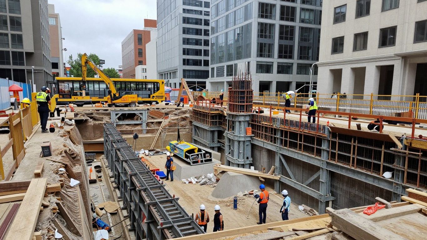
A deep excavation is a temporary structure as much as it is a ground engineering operation. The support system must remain stable through every intermediate stage, not only at the final excavation level. The design basis should therefore connect geometry, ground conditions, loads, structural details, and construction methodology from the beginning. In Singapore, this work commonly sits within the Earth Retaining Stabilising Systems framework, with checks for ultimate and serviceability limit states.
Define excavation geometry, depth, and construction sequence
Start with a reliable geometric description of the excavation, including plan dimensions, depth, wall offsets, berms, ramps, corners, and nearby permanent structures. The sequence should show when soil is removed, when each waler and strut level is installed, and when preload is applied. A model that skips an intermediate stage can miss the governing strut force or wall movement.
Temporary works are often removed later, but they must also be coordinated with partially completed permanent works. Anchors, brackets, cast-in items, and embedments may transfer temporary actions into the permanent structure, so their temporary condition should be checked rather than treated as an afterthought.
Characterize soil layers, groundwater, and adjacent structures
The geological model should reflect the available boreholes, in-situ testing, laboratory results, and groundwater observations. Soil properties vary spatially, particularly where fill, marine clay, residual soil, and competent strata occur within the same site. Groundwater levels and permeability are equally important because drawdown can alter effective stress and induce settlement outside the excavation.
Adjacent buildings, utilities, roads, tunnels, and sensitive structures should be located in relation to the wall and model boundaries. Their stiffness and foundation levels can affect ground movement, while excavation-induced displacement may impose actions on them. Settlement criteria should be selected according to the sensitivity of each asset rather than applied uniformly.
Identify temporary works design loads and load combinations
The load schedule should include retained soil, groundwater, surface surcharge, construction materials, plant, temporary platforms, wind where relevant, and actions from the support system itself. Structural temporary works also need dead, live, wind, and dynamic construction loads, with combinations selected under the governing project standard. In Singapore practice, references may include SS EN 1991-1-6 for actions during execution and BS 5975 for temporary works procedures.
The designer should also examine load transfer into walers, corner brackets, strut seats, and any permanent elements used temporarily. Installation tolerances and eccentric contact can create bending in a member that was initially conceived as axial-only.
Set performance criteria for strength, deformation, and serviceability
Performance criteria should cover overall stability, wall strength, strut capacity, connection resistance, hydraulic stability, ground settlement, wall deflection, and effects on adjacent structures. The allowable movement may differ by asset; the knowledge base identifies typical adjacent ground settlement limits in Singapore ranging from 10 mm to 25 mm depending on sensitivity. These are design criteria, not a substitute for project-specific assessment.
A clear acceptance framework makes the later FEA simulation easier to review. It also separates strength checks from serviceability checks, so a model is not judged solely by whether it converges or whether one member remains below its factored resistance.
Choose an appropriate FEA simulation strategy
The right model is the simplest one that captures the mechanisms governing the excavation. Finite element analysis divides a complex domain into smaller elements and solves the response of the assembled system; a concise finite element analysis explanation is useful for readers who need a refresher on the broader method. For deep excavations, however, the difficult part is not merely meshing the geometry. It is choosing assumptions that reflect staged construction, soil behavior, support connectivity, and three-dimensional effects.
Decide between 2D plane-strain and 3D finite element models
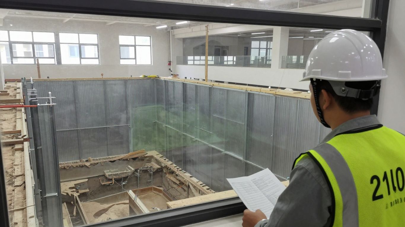
A two-dimensional plane-strain model can be appropriate for a long, regular excavation with repeated support spacing and limited variation along its length. It is efficient for studying wall deflection, earth pressure development, groundwater response, and typical cross-sections. A three-dimensional model is more appropriate where corners, irregular plans, non-uniform loading, tunnels, pile groups, or local support arrangements control the response.
PLAXIS 2D includes staged construction, consolidation, safety analysis, and flow analysis in the documented application scope. PLAXIS 3D is documented for true three-dimensional modelling of excavation corners, irregular shapes, non-uniform loading, tunnel–structure interaction, pile groups, and complex stratigraphy. The choice should follow the physical problem, not the preference for a particular software interface.
Select beam, shell, and solid elements for steel struts
Beam elements are generally useful for slender struts when axial force, bending, shear, and member stability are the main concerns. Shell elements can capture plate behavior in walers, connection plates, stiffeners, or built-up members where local distribution matters. Solid elements are reserved for short, highly three-dimensional details such as bearing blocks, complex brackets, or connection zones where stress concentrations need closer examination.
Element choice should match the design question and the available material data. Overly detailed solid modelling can give a false impression of precision if contact, weld flexibility, fabrication tolerances, and residual stress are unknown. Conversely, an idealized pin-ended beam may conceal meaningful bending caused by eccentric bearing or imperfect alignment.
Represent diaphragm walls, sheet piles, walers, and corner supports
Retaining walls may be represented with plate or shell elements when bending stiffness and wall continuity are important, or with an equivalent structural idealization when the analysis objective permits it. Sheet piles require attention to section properties, interlock behavior, embedment, and water cut-off assumptions. Walers and corner supports should be connected so that force distribution reflects their actual stiffness and bearing arrangement.
The model should distinguish between a continuous waler, discrete strut seats, and a corner node that attracts force from several directions. Contact assumptions at seats and brackets can materially change bending moments. Connection flexibility should be included when it is likely to influence the system response.
Determine when simplified frame analysis is insufficient
A simplified frame model can be valuable for preliminary sizing and an independent check, particularly for regular bays with known support levels. It becomes less reliable when soil stiffness varies significantly, wall movement affects adjacent foundations, groundwater changes during excavation, or corners and local restraints govern. It also cannot by itself reproduce the evolving stress relief in the surrounding soil.
Use FEA when the interaction between geotechnical and structural response is central to the decision. The goal is not to replace engineering judgement with a more elaborate model, but to investigate mechanisms that a frame idealization necessarily omits.
Balance model detail, computational cost, and design uncertainty
Model detail should increase where uncertainty or consequence is high. Refine around excavation corners, support seats, wall joints, interfaces, and nearby assets, while keeping remote regions sufficiently simple for stable computation. Run sensitivity cases rather than adding detail that cannot be supported by reliable input data.
A useful model hierarchy often includes a preliminary two-dimensional model, a refined design model, and a targeted three-dimensional study for local effects. This gives the team a way to compare trends and identify whether a result is controlled by geometry, soil parameters, support stiffness, or numerical assumptions.
Model soil–structure interaction and staged excavation
Deep excavation behavior develops through the interaction of soil, water, retaining elements, and supports. Removing soil releases stress, changes deformation patterns, and progressively transfers load to the wall and struts. The analysis should therefore reproduce the construction sequence rather than apply the final excavation geometry as a single static event.
Select constitutive models for different ground conditions
The constitutive model should reflect the expected stress path and the design question. Mohr–Coulomb may be suitable for preliminary analysis, while stress-dependent stiffness models are often better for deformation prediction. Time-dependent models may be needed for soft marine clay, especially where consolidation and creep affect settlements during a prolonged excavation.
The choice must be supported by investigation data and calibration. Soil stiffness, strength, dilatancy, permeability, and unloading behavior should not be selected only because they make the model converge. Where sensitive structures are nearby, small-strain stiffness may have a meaningful influence on predicted movement.
Define interface behavior between soil and retaining elements
Interfaces control how shear and normal forces pass between the ground and the wall. Their strength, stiffness, roughness, and separation behavior should reflect the wall type and installation method. A fully bonded interface may overstate load transfer, while an excessively weak interface may produce unrealistic slip and wall movement.
Review interface results alongside wall forces and soil deformation. Pay particular attention to the excavation side, wall toe, strut levels, and any contact that may open during unloading. Interface assumptions should be recorded clearly because they can be among the most influential modelling choices.
Simulate excavation, strut installation, and preload stages
Each excavation lift should be followed by installation of the relevant support, with preload applied only when and how it will occur on site. The model should include the stiffness of the newly installed member and the change in boundary conditions caused by its connection to the waler. If a strut is installed after significant wall movement, the resulting force will differ from one installed immediately after excavation.
The sequence should also include temporary access conditions, local over-excavation where relevant, and the removal or transfer of supports. Staged construction is not simply a visual animation; it determines the stress history used for subsequent calculations.
Include groundwater flow, dewatering, and consolidation effects
Groundwater may act as lateral pressure, seepage force, uplift, or a driver of consolidation settlement. Dewatering stages should be modelled with realistic water levels and drainage boundaries, including any cut-off effect provided by a secant pile or diaphragm wall. The timing of drawdown matters where low-permeability layers respond slowly.
Coupled flow and deformation analyses can be useful when water movement and settlement are closely linked. The designer should distinguish between a short-term undrained response and a longer-term drained or consolidating condition, then check both where the construction programme requires it.
Account for stress relief and construction-induced ground movement
Excavation unloads the soil and causes stress redistribution around the opening. Wall deflection, basal heave, lateral strain, and settlement behind the wall are coupled responses. The model should allow the ground to deform as excavation proceeds rather than imposing a prescribed wall displacement without explaining its origin.
Predicted movement should be compared with the location and vulnerability of adjacent foundations and utilities. The response can be reduced through support timing, wall stiffness, controlled excavation, preload, groundwater management, or ground improvement, but the selected measure must be represented in the sequence and not merely described in the method statement.
Apply realistic loads and boundary conditions
Loads and restraints are where a theoretically sound model can become misleading. A deep excavation rarely experiences one clean pressure diagram; it experiences changing surcharge, water levels, equipment positions, support reactions, and construction tolerances. Boundary conditions must be sufficiently distant and physically appropriate so they do not artificially restrain the excavation.
Calculate earth pressures, surcharge, water, and construction loads
Earth pressure should emerge from the chosen soil model and stress history where possible, with hand-calculated pressure envelopes retained as a reasonableness check. Surcharge should reflect actual storage, traffic, cranes, temporary access, and adjacent structures. Water pressure should be applied consistently with the groundwater analysis, avoiding double counting between pore pressure and external water loads.
Construction loads can move as the work progresses. A crane near one wall, a stockpile beside the excavation, or a temporary platform supported by the waler may govern a local condition even if it is not present in the final arrangement. Load cases should make these differences visible to the reviewer.
Represent strut prestress and load transfer through walers
Prestress should be introduced at the correct stage and in a way that reflects the installation procedure. The model should distinguish between a target jack force, the force actually locked into the system, and the force that develops after surrounding soil and wall movements continue. Friction, bearing, seat stiffness, and waler continuity all influence the final distribution.
The following checks help keep the load path transparent:
- Confirm that the strut is connected to the intended waler locations.
- Check whether support stiffness and preload match the installation method.
- Review force sharing at corners, raking supports, and discontinuous walers.
- Confirm that reactions are consistent with the applied loads and excavation stage.
These checks do not replace connection design. They show whether the global model is transferring force through the same parts that will carry it in the field.
Include temperature effects, creep, shrinkage, and installation tolerances
Long steel struts can develop meaningful force changes from temperature variation, particularly when restrained between stiff walls. Where concrete walers or permanent elements participate, creep and shrinkage may also change compatibility over time. These effects should be considered when the temporary support remains in place for an extended period or when the system is sensitive to small force changes.
Installation tolerances deserve equal attention. Out-of-plumb walls, eccentric seats, uneven preload, and gaps at bearing surfaces can introduce bending and unintended redistribution. A tolerance case may be more informative than a nominal model that assumes perfect alignment.
Define model boundaries and in-situ stress conditions
Lateral and vertical boundaries should be placed far enough from the excavation that their restraints do not control the result. The base boundary should represent the stiffness and restraint of the deeper ground, while the initial stress field should be compatible with soil self-weight, groundwater, and geological history.
Initial stresses should be checked before excavation begins. Excessive boundary reaction, unrealistic displacement, or a poor initial equilibrium state can contaminate every later stage. A stable initial model is a basic prerequisite for meaningful construction simulation.
Test sensitivity to uncertain soil and structural parameters
No ground model is exact. Sensitivity studies should vary parameters that materially affect wall movement and strut demand, such as stiffness, undrained strength, interface reduction, permeability, wall stiffness, support stiffness, and preload. The purpose is to identify governing combinations and decide which assumptions require field verification.
Results are most useful when reported as ranges with an explanation of the controlling variable. A single highly precise force can be less informative than a bounded result that shows how much it changes when the soil or support assumptions are adjusted.
Capture nonlinear behavior and stability risks
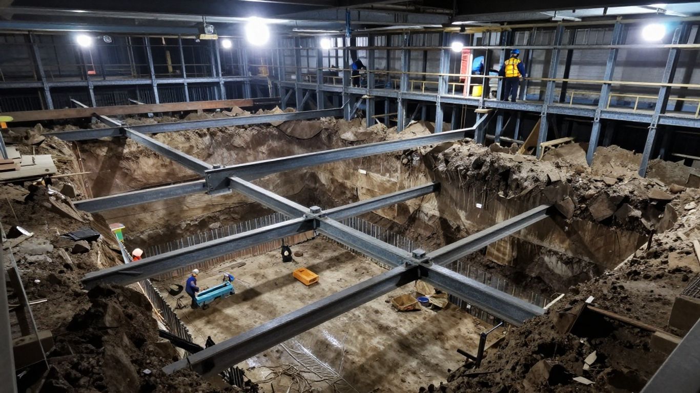
Steel strutting systems can fail through several interacting mechanisms. A member may buckle globally, yield locally, lose bearing, or transfer unexpected force into a waler and wall. Soil failure, basal heave, hydraulic uplift, and geometric changes can further reduce the available stability. Nonlinear analysis should be used to investigate these risks where linear elastic results do not describe the likely behavior.
Evaluate geometric nonlinearity and second-order effects
Geometric nonlinearity allows the analysis to account for changing member geometry and the additional moments caused by axial force acting through lateral displacement. This is especially relevant for long, heavily compressed struts with modest initial curvature or eccentricity. The analysis should use appropriate load stepping and convergence controls so that a numerical difficulty is not mistaken for a physical failure.
Second-order effects should be reviewed at member and system levels. A strut that appears adequate under first-order force extraction may have materially lower resistance once deflection and force eccentricity are included.
Perform eigenvalue buckling analysis for steel struts
Eigenvalue buckling analysis provides a useful indication of idealized instability modes and critical load factors. It can identify whether the governing mode is a single-member bow, a sway mode, a waler interaction, or a broader frame mechanism. The result is an ideal reference, not a complete resistance check, because real systems contain imperfections, residual stress, connection flexibility, and nonlinear material behavior.
Use the mode shapes to guide the nonlinear model and to review restraint assumptions. An unexpectedly high factor may indicate that the model has provided unrealistic lateral restraint rather than that the physical strut has abundant reserve.
Introduce initial imperfections and residual stresses
Initial imperfections can be represented through measured or code-consistent out-of-straightness, installation offsets, or scaled buckling modes. Residual stresses from fabrication and welding may also affect the onset of yielding and buckling. The selected values should be documented and varied where they have a strong influence on capacity.
Imperfection sensitivity is often greatest near a critical load. Running more than one plausible imperfection pattern can reveal whether the design is dependent on a favorable shape that would be unlikely to occur in practice.
Assess local, member, and system-level buckling interaction
Local plate buckling, member buckling, and system sway should be examined as related but distinct phenomena. A slender box, pipe, or built-up strut may have local slender elements that reduce its effective section before global buckling develops. Walers and corner restraints can change effective lengths and couple the behavior of several supports.
The design review should connect finite element modes with code-based resistance checks. A global model is not a replacement for checking section classification, effective lengths, welds, bolts, bearing, and splice details.
Investigate nonlinear failure modes and post-buckling response
Material nonlinearity, contact separation, yielding, and large displacement can help identify how failure develops after the elastic limit. Post-buckling results should be interpreted carefully because numerical stabilization, imperfections, and boundary assumptions strongly influence the path. The objective is usually to understand reserve, ductility, and warning signs rather than to justify uncontrolled deformation.
If the model shows rapid loss of stiffness, concentrated yielding, or a mechanism near a support level, revisit the construction sequence and load path. A redesign may involve a larger strut, shorter effective length, additional restraint, stronger connection, or a different installation sequence.
Interpret FEA simulation results for steel strut design
Post-processing should begin with equilibrium and the complete load path, then move to member resistance and serviceability. Peak contours alone can be deceptive, particularly near point restraints, sharp corners, and idealized contacts. The reviewer should understand where forces originate, how they move through the system, and whether the extracted result corresponds to a realistic design location.
Review axial forces, bending moments, shear forces, and reactions
For each critical stage, extract axial force, bending moment, shear, torsion where relevant, and end reactions. Plot envelopes along the strut rather than reviewing only a maximum value. Compare the force pattern with the expected support level and soil response, and investigate abrupt changes that may indicate a modelling discontinuity.
Reactions at walers, seats, corners, and wall interfaces should balance the applied actions. Any unexplained imbalance is a warning to check connectivity, sign conventions, duplicated loads, or inactive elements.
Check strut capacity, slenderness, and combined axial-flexural behavior
The strut check should account for section capacity, slenderness, effective length, buckling curve or equivalent design method, and combined axial and flexural actions. Moments may arise from eccentric bearing, wall convergence, differential movement, connection stiffness, or installation tolerance. A nominally compression-only member should not be cleared without checking these secondary actions.
Use the governing force envelope from relevant construction stages, not only the final excavation stage. Temporary structures often experience their highest demand while the system is incomplete or while one support level has not yet been installed.
Assess waler forces, connection demands, and bearing details
Waler design requires more than distributing strut reactions along a line. Check bending between supports, shear near seats, torsion at corners, local web or flange effects, stiffeners, splice locations, and bearing stresses. Connections should be designed for the force and eccentricity actually delivered by the model, including tolerances and possible redistribution.
Where temporary supports connect to permanent works, verify anchors, brackets, embedments, and cast-in items for both temporary and permanent load conditions. The interface between the two systems should be shown clearly in drawings and construction information.
Evaluate retaining wall deflections and ground settlements
Wall deflection profiles should be reviewed at each excavation stage, including movement near the top, support levels, and toe. Ground settlement behind the wall should be mapped against nearby foundations, utilities, pavements, and tunnels. Differential movement and angular distortion may matter more than a single maximum settlement value.
The predicted pattern should make physical sense. A sudden isolated spike at one node may be numerical, while a broad settlement trough linked to drawdown or wall movement may require mitigation and monitoring.
Compare results against strength and serviceability limits
Results should be compared with the adopted design code, project criteria, and asset-specific tolerances. Strength checks cover member, wall, waler, connection, hydraulic, and overall stability conditions. Serviceability checks cover deformation, settlement, angular distortion, vibration where relevant, and the continued usability of adjacent infrastructure.
STAAD Pro is documented for assessing building response to predicted ground movements through three-dimensional structural modelling, applied support settlements and lateral displacements, and evaluation of member stresses, moments, and deformations. Used within that documented scope, it can support the assessment of affected structures alongside the geotechnical model.
Verify the model and translate results into construction controls
A credible analysis is not complete when the solver produces a result. Verification asks whether the numerical model is behaving as intended, while validation asks whether its assumptions are consistent with observed ground and structural response. The final design package should make those checks auditable and convert the analytical predictions into actions that site teams can understand.
Perform mesh refinement and numerical convergence checks
Refine the mesh around walls, strut seats, corners, interfaces, and zones with steep stress or displacement gradients. Compare displacements, reactions, and member forces as the mesh changes. A local peak that grows indefinitely with refinement may be a stress singularity rather than a design force to use directly.
Convergence should also be checked across load steps and nonlinear iterations. Record tolerances, stabilization methods, failed steps, and any manually adjusted parameters. These details can materially affect interpretation of a nonlinear result.
Compare finite element results with hand calculations and simpler models
Hand calculations provide independent envelopes for earth pressure, water pressure, strut reactions, wall bending, and member resistance. A simple frame model can test whether the global support arrangement gives broadly comparable force distribution. Differences are expected, but they should be explainable through soil flexibility, staging, corners, or contact behavior.
A comparison that is close for the wrong reason is not useful. Check units, section properties, load factors, effective lengths, groundwater assumptions, and support conditions before drawing conclusions from agreement or disagreement.
Validate assumptions using field instrumentation and monitoring data
Instrumentation may include wall inclinometers, survey points, settlement markers, piezometers, strut load cells, and building movement points. Monitoring should begin before excavation where possible, establishing a baseline against which stage-by-stage changes can be assessed. Observed trends can support or challenge assumed stiffness, groundwater response, preload, and wall behavior.
The model should not be tuned casually to match one reading. Review spatial patterns, timing, measurement uncertainty, and whether the construction stage represented in the model matches the stage on site. Significant divergence should prompt a structured review and, where necessary, revised predictions.
Define trigger levels and contingency actions
Trigger levels should be tied to measurable quantities such as wall movement, settlement, pore pressure, strut load, crack width, or survey displacement. Each level needs a predefined response, an owner, a communication route, and a practical mitigation measure. Actions may include pausing excavation, checking instruments, adding or adjusting support, reducing surcharge, improving drainage, or carrying out a focused engineering review.
A trigger is only useful when the team can act before the limit is exceeded. Monitoring frequency should increase during critical excavation stages and after unusual weather, water-level change, impact, or support installation difficulty.
Document design assumptions, staging, checks, and inspection requirements
The final package should identify the design basis, soil parameters, groundwater assumptions, model dimensions, element types, interfaces, construction stages, load combinations, imperfections, convergence settings, and acceptance criteria. Drawings should show member sizes, connections, preload requirements, tolerances, access constraints, inspection points, and the sequence for installation and removal.
Inspection should confirm wall condition, waler continuity, seat bearing, strut alignment, preload, bolt and weld details, drainage, and any cast-in support items. Clear records connect the FEA simulation to the temporary works that are actually built.
Conclusion
Heavy steel strutting systems demand a design process that combines geotechnical understanding, structural mechanics, staged construction analysis, and site control. A well-calibrated model can clarify force transfer and movement, but only when its assumptions are checked against simpler calculations, field observations, and the realities of installation. The most dependable temporary works design is therefore not the most elaborate model; it is the one that remains understandable, verifiable, and useful throughout construction.
Frequently Asked Questions
What is the main purpose of FEA simulation in deep excavation design?
It is used to study the interaction between soil, groundwater, retaining elements, and temporary supports through the excavation sequence, helping engineers estimate forces, movements, and stability risks.
When is a 3D model needed instead of a 2D model?
A 3D model is generally warranted for irregular excavation plans, corners, non-uniform loads, nearby tunnels or pile groups, inclined strata, and other conditions where out-of-plane behavior may govern.
Why must excavation be modelled in stages?
Each excavation lift changes stress, deformation, groundwater conditions, and support engagement. Staged modelling captures the sequence in which the temporary works actually begin to carry load.
Which loads should be considered for steel struts?
Typical actions include earth pressure, water pressure, surcharge, construction equipment, temporary platforms, preload, temperature, installation tolerances, and effects transferred through walers and connections.
Can a strut be designed for axial compression only?
Not automatically. Eccentric bearing, wall movement, imperfect alignment, connection stiffness, and second-order effects can introduce bending and shear, so combined axial-flexural behavior should be checked.
How are excavation-induced settlements controlled?
Control measures include adequate wall stiffness, timely support installation, suitable preload, groundwater management, controlled excavation, appropriate surcharge restrictions, monitoring, and predefined contingency actions.
What makes an excavation model reliable?
Reliability comes from sound site investigation, suitable constitutive and interface models, realistic staging, mesh and convergence checks, independent calculations, sensitivity studies, and comparison with instrumentation during construction.