
Key Takeaways
Eurocode 7 provides the limit-state framework for Singapore ERSS, but a compliant design also depends on local ground conditions, construction stages, and movement control.
- ULS checks resistance against collapse, instability, hydraulic failure, and structural failure.
- SLS checks movements, settlement, deformation, and effects on neighbouring assets.
- Groundwater and soil variability must be reflected in the design model and investigation plan.
- Excavation sequencing, temporary conditions, and monitoring are part of the engineering decision.
- Clear calculations, independent checking, and construction records support authority review.
1. Understand how Eurocode 7 applies to Singapore ERSS design
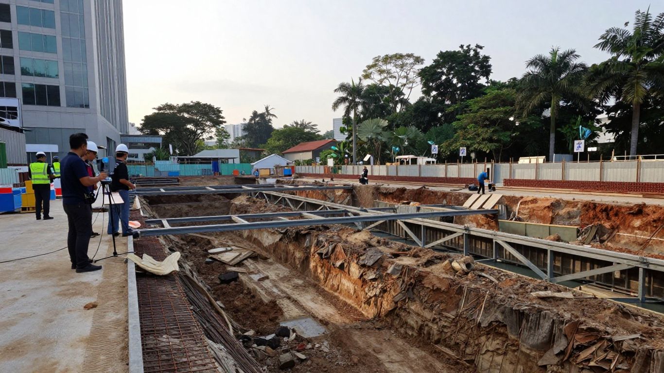
Earth Retaining and Stabilising Systems (ERSS) are temporary works, but their consequences can extend well beyond the excavation boundary. In Singapore’s dense urban environment, the system must retain soil, manage groundwater, protect adjacent structures, and remain workable through every excavation stage. SS EN 1997-1, the Singapore adoption of Eurocode 7, supplies the limit-state design philosophy for these decisions. The design therefore has to address both resistance to failure and acceptable performance during construction.
The role of SS EN 1997 in earth-retaining and support systems
SS EN 1997 establishes the geotechnical design principles used to verify ERSS against relevant Ultimate Limit States (ULS) and Serviceability Limit States (SLS). It does not replace engineering judgement or a project-specific ground model. Rather, it gives the designer a consistent basis for applying actions, soil parameters, water pressures, resistance models, and partial factors.
For an ERSS, the limit states may involve overall stability, structural failure, hydraulic failure, excessive deformation, or loss of support during a temporary stage. A wall that appears adequate at final excavation may still be vulnerable while a strut level is being installed or removed. Each meaningful design situation must therefore be identified and checked rather than treating the completed support arrangement as the only condition that matters.
Singapore-specific requirements alongside Eurocode 7
Singapore projects must be read against the Building Control Act and Regulations, applicable Singapore Standards, and the requirements of relevant authorities. For deep excavations, the regulatory setting places particular weight on site investigation, professional responsibility, safety, and protection of surrounding property and infrastructure. The design team should confirm the current submission and endorsement requirements at the start of the project, rather than assuming that a generic Eurocode calculation package is sufficient.
Local conditions also shape the engineering. Singapore commonly presents soft deposits, high groundwater levels, intense rainfall, constrained sites, and sensitive neighbouring utilities or structures. A design approach that is technically familiar elsewhere may require different assumptions about seepage, drainage, movement limits, access, or installation tolerances here. Aman Engineering Consultancy’s regional practice is grounded in professional engineering consultancy, design endorsement, and adherence to SS and Eurocode requirements; those principles are relevant when coordinating an ERSS submission.
How ERSS design interacts with geotechnical and structural design
An ERSS is neither purely a soil problem nor purely a steel or concrete problem. The geotechnical model determines earth and water actions, embedment behaviour, basal stability, and soil-structure interaction. The structural design then verifies walls, walers, struts, anchors, connections, and any interfaces with permanent works under the calculated actions.
The two disciplines must exchange assumptions continuously. Wall stiffness affects predicted ground movement; support stiffness affects load redistribution; installation sequence affects the condition in which each component starts carrying load. Where temporary supports bear on partially completed permanent works, those permanent elements also need checking in their temporary condition.
A useful coordination point is to distinguish the design question from the calculation method. Numerical modelling can provide detailed response predictions, but it cannot correct an unrealistic groundwater profile, an unsuitable soil parameter, or an omitted construction stage. The model is only as reliable as the information and assumptions supplied to it.
The importance of site investigation and ground parameter selection
Geotechnical investigation forms the foundation of ERSS design. Singapore’s Building Control Regulations mandate comprehensive site investigation for deep excavation projects, with investigation commonly including boreholes, in-situ testing such as SPT, CPT, and pressuremeter testing, laboratory testing, and groundwater monitoring. Borehole spacing may typically fall in the range of 15 to 30 metres, subject to the project and ground variability.
The resulting geological model should describe not only representative soil layers but also their spatial variability, weaker seams, fill, obstructions, permeable horizons, and possible geohazards. Characteristic values for strength, stiffness, unit weight, permeability, and interface behaviour should be selected with the design situation in mind. Using a single optimistic parameter set across the whole site can conceal the mechanism that actually governs.
2. Identify the main failure mechanisms for ERSS
ERSS design begins with a clear view of how the system could fail. Failure may occur through the retained ground, at the wall-soil interface, through the support members, or by an unexpected groundwater path. Some mechanisms are sudden, while others develop through progressive movement and loss of support. Considering them separately and in combination helps the designer select meaningful ULS and SLS checks.
Overall stability and ground-bearing failure
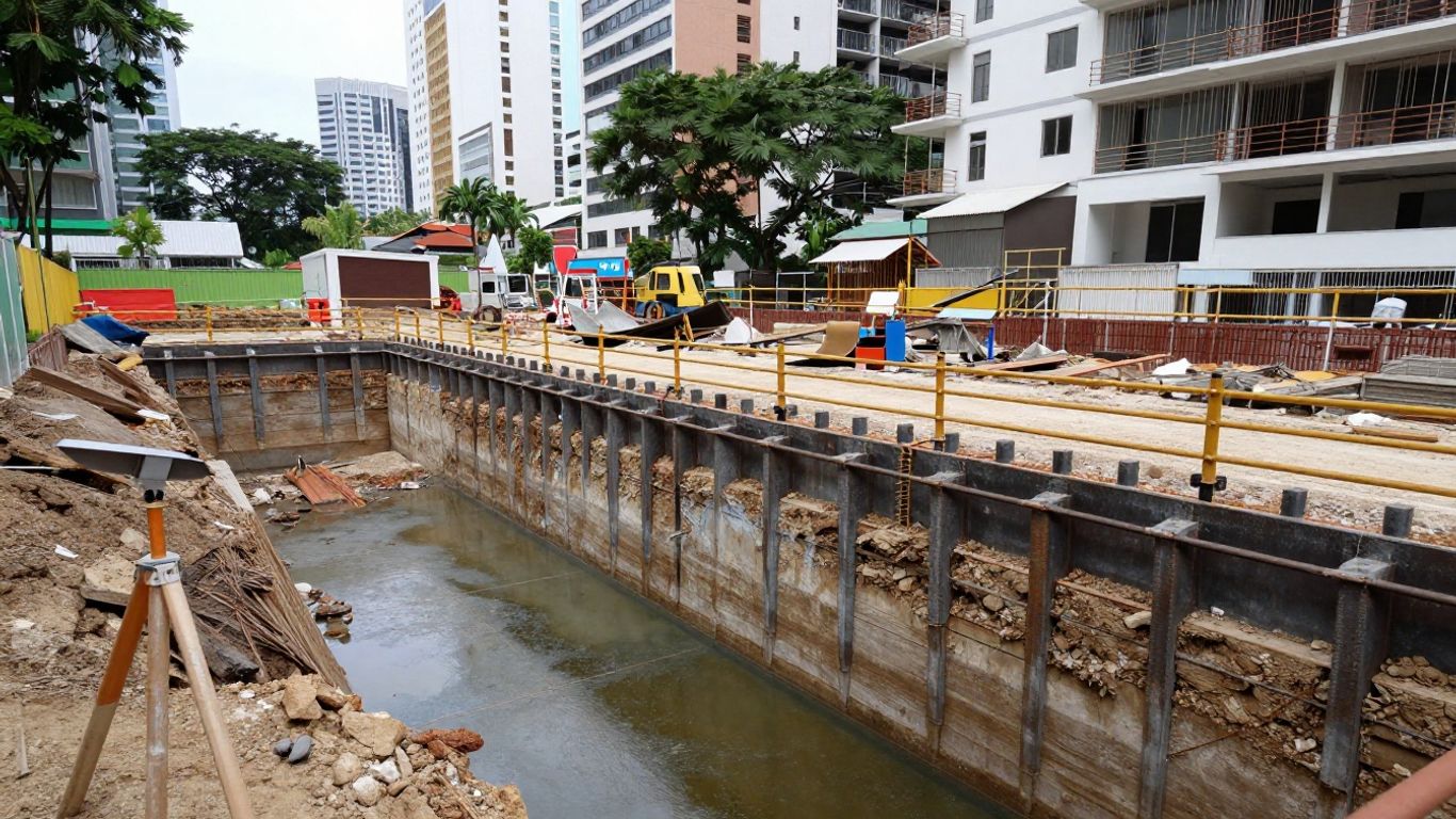
Overall stability considers whether the retained soil mass, wall, supports, and surrounding ground can act as a stable system. Potential slip surfaces may pass behind the wall, beneath the excavation, or through a combination of retained and underlying strata. The analysis should include relevant surcharges, adjacent foundations, construction loads, groundwater, and the geometry of the actual excavation stage.
Ground-bearing failure is another concern where concentrated reactions from struts, walers, king posts, or temporary bases are transferred into relatively weak soil. Local bearing resistance may be inadequate even when global stability appears satisfactory. The designer should check load introduction areas, contact pressures, eccentricity, and any change in soil condition caused by excavation or seepage.
Sliding, overturning, and basal heave
For flexible or cantilevering walls, sliding and overturning are linked to the balance between active and passive pressures, surcharge, hydrostatic pressure, wall embedment, and support reactions. The available passive resistance must not be assumed without considering whether the soil can mobilise it at the required displacement and whether groundwater alters the effective stresses.
Basal heave is particularly relevant in soft clay or other weak deposits beneath the excavation. Removal of overburden reduces confinement, while the retained soil and surcharge outside the excavation continue to impose stress. A credible assessment considers the undrained and drained behaviour appropriate to the stage, the depth of the weak stratum, wall embedment, and any support provided by the wall or base slab.
Global stability of the retained soil mass
Global stability is broader than checking the wall section. A deep-seated mechanism can include the wall, retained soil, support system, and foundation of a neighbouring structure. It may be triggered by a weak layer, a change in ground level, excavation near a slope, or an unrecognised groundwater pressure.
The assessment should use a geometry and ground model that reflect the surrounding site, not merely a narrow wall cross-section. Where soil properties vary materially, sensitivity checks can show whether the governing slip mechanism changes with the assumed strength or groundwater level. This is often more informative than reporting a single factor of safety without explaining the controlling surface.
Structural failure of walls, struts, walers, and anchors
Structural ULS checks cover bending, shear, axial force, buckling, local instability, connection capacity, and service-stage deterioration where relevant. Wall sections may be steel sheet piles, bored pile arrangements, reinforced concrete diaphragm walls, or secant pile walls. Walers and struts need checks for load distribution, eccentricity, connections, and installation tolerances.
Anchors introduce additional issues, including tendon capacity, bond length, stressing, proof testing, corrosion protection, and the influence of neighbouring land or services. Their force is not independent of wall movement and construction sequence. A structural check that uses a convenient support force without confirming how that force develops can miss the governing interaction.
Effects of groundwater, seepage, and piping
Water pressure can substantially increase lateral actions and reduce effective soil strength. Singapore’s high groundwater table means that seepage, drawdown, leakage through joints, and water accumulation should be treated as design matters rather than site housekeeping. Hydraulic failure may involve piping, internal erosion, uplift, excessive inflow, or instability caused by an unbalanced water level.
The design should define credible water levels and drainage conditions for both normal and adverse situations. It should also explain how the assumed conditions will be achieved and maintained. A watertight wall, cut-off, sump, wellpoint system, or staged pumping arrangement each has different construction and monitoring implications.
3. Apply the Ultimate Limit State approach
ULS design asks whether the ERSS and surrounding ground have adequate resistance against collapse or a comparable loss of function. The check is not limited to the final wall section; excavation stages, temporary supports, rainfall, groundwater changes, and construction loads may create more severe situations. Eurocode 7 uses partial factors applied to actions and material properties, with the selected design approach and National Annex requirements controlling how the verification is performed. Sound ULS work makes the failure mechanism and design situation visible.
What ULS verification means for ERSS
A ULS verification compares design effects with design resistance for a defined failure mode. Depending on the mechanism, this may involve equilibrium, soil strength, hydraulic gradients, bearing resistance, wall capacity, strut stability, or connection strength. The calculation should state what is being verified and what assumptions allow the resistance to be mobilised.
ULS is about adequate safety against unacceptable failure, not about predicting the exact movement that will occur. A wall can pass a ULS check while still producing movements that damage a fragile building or distort a utility. That is why ULS and SLS must be developed together rather than treating SLS as an optional refinement.
Geotechnical and structural design approaches under Eurocode 7
Geotechnical ULS checks may include sliding, overturning, bearing, basal heave, global stability, hydraulic failure, and soil-structure interaction. Structural checks then use the resulting actions or envelopes to design the wall and support components. Depending on the system and analysis method, the load transfer between these checks may be iterative.
For example, a stiff diaphragm wall may attract different support forces from a flexible sheet pile wall. A two-dimensional model may need carefully considered boundary conditions, while a three-dimensional arrangement may be needed where corners, cross-lot struts, ramps, or irregular excavation geometry control behaviour. The chosen method should be proportionate to the risk and capable of representing the governing mechanism.
Design situations, load combinations, and partial factors
The designer should list persistent, transient, accidental, and construction-stage situations that are relevant to the site. These may include normal excavation, temporary open cuts, support installation, support removal, abnormal surcharge, flooding, loss of a drain, or an unplanned change in groundwater. Actions from cranes, stockpiles, traffic, adjacent buildings, and temporary platforms should be assigned to the stages in which they can occur.
A practical schedule of design situations helps prevent omissions. It should identify the stage, geometry, support condition, groundwater assumption, key actions, and required ULS or SLS verification. Partial factors must follow the applicable Singapore provisions and selected design approach; they should not be copied from an unrelated project or software default without review.
Selection of characteristic soil and water pressures
Characteristic values are engineering estimates of ground properties and actions that account for uncertainty. They should be derived from investigation data, laboratory results, comparable experience where justified, and a model of spatial variability. Earth pressure selection should reflect wall movement, drainage, construction sequence, surcharge, and the difference between total and effective stress conditions.
Water pressures deserve separate treatment. Assuming a drained excavation simply because pumping is planned may be unsafe if the system can lose pumping capacity or if a low-permeability layer traps water. Conversely, applying full hydrostatic pressure without considering a verified cut-off or drainage system may distort the design. The report should make the water model auditable and identify what field observations would challenge it.
ULS checks for excavation stages and temporary conditions
Every excavation lift changes the geometry and the support reactions. The most critical stage may occur before a new strut is fully engaged, during a delay between excavation and support installation, or while a temporary support is being removed. Construction tolerances and partial completion should be represented where they can materially affect capacity.
ULS stage checks should cover the wall, supports, ground, and water regime as one evolving system. They should also address temporary conditions of permanent works, including cast-in items, brackets, embedments, and slabs that receive temporary reactions. Aman Engineering Consultancy can support projects that require professional engineering consultancy and design endorsement aligned with Singapore Standards and Eurocode-based requirements, but the project team remains responsible for providing complete and accurate design inputs.
4. Apply the Serviceability Limit State approach
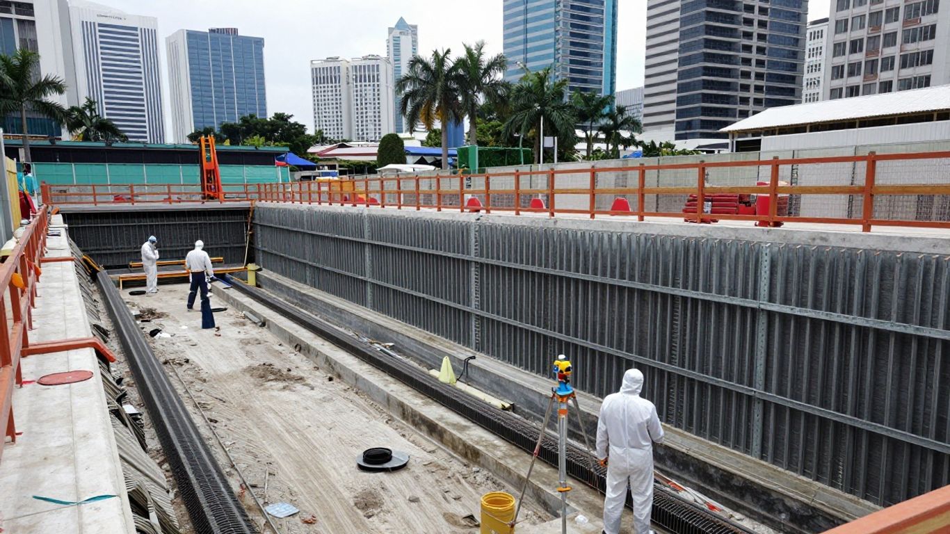
SLS design addresses whether the ERSS performs acceptably without excessive movement, settlement, vibration, leakage, or deformation. In a constrained Singapore site, this question may govern even when calculated ULS reserves are comfortable. The affected asset could be a neighbouring building, road, rail structure, buried utility, or the excavation itself. Movement predictions must therefore be connected to damage sensitivity and construction controls.
What SLS verification means for ERSS
An SLS verification compares predicted or assessed response with project-specific performance criteria. Relevant responses include wall deflection, ground settlement, strut movement, anchor extension, slab movement, groundwater drawdown, and vibration. The criteria should be agreed with the relevant stakeholders and tied to the sensitivity of nearby assets.
SLS analysis is not simply a lower-load version of ULS analysis. Soil stiffness, stiffness degradation, unloading and reloading, wall flexibility, support preloading, and installation effects influence the result. The model should explain whether the predicted movement is an estimate, an upper-bound assessment, or a value intended for comparison with an alert level.
Ground movements behind the excavation
Ground movement behind an excavation depends on wall stiffness and embedment, support spacing, excavation depth, construction sequence, soil compressibility, groundwater, and workmanship. Deflection can be concentrated near an excavation level or develop progressively as the wall and supports respond to unloading. Settlement behind the wall may extend farther than expected, especially where soft compressible deposits or utility trenches are present.
The assessment should examine both the magnitude and distribution of movement. A small maximum value may still be unacceptable if it occurs directly beneath a brittle service or foundation. Conversely, a larger movement in an open area may have limited consequence. This is why movement contours and asset-specific assessment are generally more useful than a single headline number.
Wall deflection, strut movement, and support deformation
Wall deflection is affected by section stiffness, connection behaviour, embedment, support level, preload, and the timing of support installation. Struts can shorten or move as load develops, while walers may distribute forces unevenly where the wall is irregular or installation is imperfect. Anchors may experience extension, creep, or changes in bond performance.
The calculation should include realistic support stiffness and construction tolerances. If a strut is assumed to be perfectly fixed, or a wall is assumed to have no installation imperfection, the predicted response may be misleading. The design team should also consider whether a deformation is recoverable, permanent, or likely to redistribute load into another component.
Settlement risks to adjacent buildings and utilities
Adjacent foundations can impose surcharge and may be sensitive to differential settlement, lateral strain, vibration, or groundwater changes. Utilities may have limited flexibility, particularly at joints, connections, and transitions between supported and unsupported ground. Rail corridors and operational infrastructure often require tighter controls than an unoccupied site.
The assessment should map assets, classify their sensitivity, and identify movement pathways. Protection may involve increased wall stiffness, reduced excavation width, closer support spacing, underpinning, staged excavation, controlled pumping, or revised construction access. The correct measure depends on the failure consequence, not solely on the calculated wall capacity.
Monitoring criteria and acceptable movement limits
Monitoring should be designed around decisions. Survey points, inclinometers, piezometers, strut load cells, settlement markers, crack gauges, and utility observations can show whether the actual response remains consistent with the design model. The monitoring plan should define baseline readings, reading frequency, alert and action levels, responsible parties, and the response to a trigger.
Allowable ground settlement adjacent to Singapore excavations is often described as roughly 10 to 25 mm, but an appropriate limit depends on the sensitivity and condition of nearby structures and utilities. That range should not be treated as a universal acceptance criterion. Project-specific movement limits should be established before excavation and reviewed against observed trends rather than isolated readings.
5. Compare ULS and SLS decisions in practical ERSS design
ULS and SLS answer different questions, yet they influence the same design choices. ULS may indicate that a wall, support, or soil mass has adequate resistance, while SLS may show that the proposed flexibility creates unacceptable movement. Conversely, a very stiff arrangement may perform well for movement control but introduce difficult connections, high installation loads, or temporary works that are impractical to build. The preferred system is the one that manages both safety and performance through the actual construction sequence.
Why a safe ULS design can still fail SLS requirements
Strength capacity does not directly limit every movement that matters. Soil can deform substantially while remaining below its failure strength, and a flexible wall can mobilise passive resistance through movement before reaching a ULS condition. Nearby assets may be damaged by differential settlement long before an ERSS wall reaches its structural capacity.
This distinction is especially important where the excavation is close to existing foundations or services. A design review should ask not only whether the wall will stand, but also whether the predicted response is compatible with the surrounding environment. SLS can consequently govern wall thickness, section selection, support level, excavation width, and monitoring intensity.
How stiffness influences deformation and construction risk
Increasing wall or support stiffness generally reduces deformation, but it does not remove uncertainty. Installation quality, joints, gaps, strut fit-up, soil variability, and groundwater can still control the observed response. A nominally stiff wall with poor continuity may perform less effectively than its analysis suggests.
Stiffness also affects load paths. A diaphragm or secant pile wall may attract larger support forces than a more flexible system, requiring stronger walers, struts, connections, and temporary bases. The design should weigh deformation reduction against the ability to install, preload, inspect, and remove the supports safely.
Balancing excavation depth, support spacing, and constructability
Support spacing is a design variable with both geotechnical and construction consequences. Closer levels can reduce wall span and movement, but they may restrict access, interfere with basement works, and increase congestion. Wider spacing may simplify excavation but require stronger wall sections and produce larger deflections.
A sound option study considers the whole sequence, including plant access, lifting, welding or bolting, concrete placement, waterproofing, slab construction, and support removal. It should also account for the time each temporary condition remains in place. The cheapest arrangement on a plan may not be the lowest-risk arrangement in the field.
When movement control governs over strength capacity
Movement control tends to govern where the excavation is deep, the retained ground is soft or compressible, groundwater is high, or neighbouring assets are sensitive. It may also govern when there is little space for a wall to deflect without affecting a road, rail corridor, or utility. In those situations, the design may need to prioritise stiffness and sequencing even when the ULS checks show spare capacity.
A useful decision process is to identify the consequence of movement first, then compare feasible systems against both ULS and SLS criteria. This keeps the design tied to the project’s actual risk rather than to a single numerical margin.
Example decisions for sheet pile, diaphragm, and secant pile systems
Sheet pile walls are commonly used in Singapore for temporary excavations in soft soils and waterfront structures. Their selection involves section properties, embedment, active and passive pressures, hydrostatic pressure, and support arrangement. They may be attractive where installation and recovery are feasible, but vibration, interlock leakage, and wall flexibility require careful consideration.
Secant pile walls use interlocking bored piles and can provide water-tightness for deep excavations up to about 30 metres. Diaphragm walls are reinforced concrete walls constructed in situ and are suited to very deep excavations exceeding 30 metres. These descriptions are starting points, not automatic selections: site access, groundwater, adjacent assets, tolerances, and construction sequence remain decisive.
6. Integrate analysis, construction sequencing, and monitoring
An ERSS design becomes meaningful only when it can be constructed and controlled. The analysis should follow the sequence by which soil is removed, supports are installed and loaded, slabs are cast, and temporary elements are changed. Monitoring then provides evidence about whether the assumed behaviour is occurring. This creates a feedback loop between design intent and field performance without replacing the need for pre-construction verification.
Staged excavation analysis for ERSS
Staged analysis should represent the initial ground state, wall installation where relevant, excavation lifts, support activation, groundwater changes, and construction of permanent restraints. The timing between stages can matter, particularly in soft clay, where consolidation or creep may influence response. Corners, ramps, openings, and changes in wall alignment should be considered where they affect three-dimensional behaviour.
The output should be reviewed as a sequence rather than as a collection of final envelopes. Sudden changes in wall movement, support force, or pore pressure may indicate an unrealistic stage, a missing mechanism, or a condition that needs field control. The analysis should also identify which observations would justify a design update.
Effects of installation methods and construction tolerances
Installation can alter the ground before excavation begins. Driving sheet piles may cause vibration and displacement; bored pile construction may create gaps, inclusions, or bentonite-related defects; diaphragm wall panels may have joint and verticality tolerances. These effects can influence both the initial condition and the eventual water-tightness of the system.
The method statement should therefore be considered during design. Tolerances for wall position, verticality, support level, strut fit-up, anchor inclination, and excavation level should be stated where they affect performance. If the design depends on an unusually precise condition, that dependency should be visible to the contractor and checked during construction.
Instrumentation for wall movement, ground settlement, and strut loads
Instrumentation should match the possible mechanisms and the decisions the project team may need to make. A compact monitoring programme commonly combines several observation types:
- Inclinometers or survey points to track wall movement and its distribution.
- Settlement markers and precise levelling points to identify ground and pavement response.
- Piezometers to monitor groundwater and pore-pressure changes.
- Load cells or strain measurements to observe strut or waler force development.
The value of these instruments lies in timely interpretation, not simply in collecting readings. Trends should be compared with baseline behaviour, excavation stage, rainfall, pumping, and nearby construction activity. A reading that is stable in isolation may still be concerning if the rate of movement is increasing.
Observational methods and design updates during construction
The observational method requires predefined observations, design expectations, trigger values, and response measures. It is not a licence to proceed without a sufficiently developed design. Before excavation, the team should establish what behaviour is acceptable, what would constitute an alert, and what practical actions can be taken if the response departs from the model.
Possible responses include slowing excavation, installing a support earlier, adding temporary bracing, reducing pumping, improving drainage, restricting surcharge, or increasing survey frequency. Any change should be assessed by the responsible professionals and recorded with its technical basis. The revised condition should then be checked for both ULS and SLS implications.
Coordination among C&S Design Engineers, geotechnical engineers, and contractors
Coordination is most effective when design assumptions are translated into site controls. The geotechnical engineer, structural designer, temporary works team, contractor, resident engineer, and relevant Professional Engineers should share the same ground model, stage drawings, monitoring plan, and trigger-action process. Roles should be clear before work starts.
The phrase C&S Design Engineers may refer to the structural and civil design interface, but the critical requirement is functional coordination: someone must own each assumption, check, approval, and field response. Aman Engineering Consultancy’s positioning in professional consultancy and back-to-back engineering endorsement is relevant where a project needs coordinated design responsibility across standards and jurisdictions. For broader engineering context, C&S Design & Engineering is an example of a firm presenting framework design as part of its engineering services; it is not a basis for ERSS-specific technical assumptions.
7. Document compliance and review the completed ERSS design
A technically sound ERSS can become difficult to approve or construct if the design record is incomplete. The report should allow an independent reviewer to trace each input through the model, calculation, drawing, specification, and monitoring requirement. It should also distinguish design assumptions from verified site information. Clear documentation reduces the risk that a temporary condition is overlooked when the project changes.
Required design inputs, assumptions, and geotechnical parameters
The design record should identify site geometry, excavation levels, wall alignment, support levels, adjacent structures, utilities, traffic or construction surcharges, groundwater observations, drainage assumptions, and the proposed sequence. The geotechnical section should explain the geological model, investigation coverage, characteristic parameters, spatial variability, and design groundwater levels.
Where parameters are correlated or derived from tests, the basis should be stated. The report should also record uncertainties, exclusions, construction tolerances, and conditions that require confirmation before excavation. A reviewer should not have to infer whether a water level or surcharge was included.
Presentation of ULS and SLS calculation results
ULS results should be presented by failure mode and design situation, with the relevant design actions, resistances, factors, and utilisation or margin clearly identified. SLS results should show predicted movements, support forces or deformations, groundwater response, and comparison with project-specific criteria. Graphs and contours are useful when they are accompanied by an explanation of the governing stage and location.
A concise result table can make the relationship between the two limit states easier to review. The table should not replace calculations, but it can show which design decision each check informs.
| Design aspect | ULS question | SLS question | Typical design response |
|---|---|---|---|
| Wall and embedment | Is resistance adequate against instability? | Is wall movement acceptable? | Revise section, embedment, or support levels |
| Struts and walers | Is capacity and stability adequate? | Are force changes and deformation controlled? | Adjust member size, preload, or spacing |
| Ground and foundations | Is global or basal failure prevented? | Are settlement and differential movement tolerable? | Stage excavation or protect adjacent assets |
| Groundwater | Is hydraulic failure prevented? | Is drawdown or leakage acceptable? | Improve cut-off, drainage, or pumping controls |
The table becomes useful only when the report explains how the governing result affects the selected arrangement. A passing ULS row should not obscure an SLS movement that exceeds the agreed criterion, and a low deformation prediction should not obscure an unverified water-control assumption.
Design checks for temporary and permanent load cases
The ERSS report should distinguish temporary construction cases from permanent load cases and identify any interaction between them. A permanent slab may become a prop, a temporary bracket may transfer force into a permanent wall, or an anchor may require a cast-in item that remains in the completed structure. These interfaces need coordinated design rather than separate calculations with incompatible assumptions.
Load cases should cover the condition during installation, normal excavation, support removal, unusual surcharge, groundwater variation, and any period in which permanent works are incomplete. Drawings should match the checked geometry and show sequence-critical details such as connection plates, bearing zones, access openings, and removal provisions.
Independent checking, professional endorsement, and authority submissions
Independent checking provides a separate examination of assumptions, methods, calculations, drawings, and construction-stage risks. The level of checking should reflect the excavation depth, complexity, consequence of failure, and sensitivity of surrounding assets. It should be completed early enough for findings to influence the design, not merely recorded after the issue of construction documents.
Authority submissions should follow the applicable Building Control, Singapore Standard, and project requirements. Professional endorsement should be provided by the appropriately appointed engineer, with responsibilities and limits clearly defined. Aman Engineering Consultancy provides professional engineering consultancy with a focus on Singapore and international compliance, including design and back-to-back engineering endorsement; any appointment should still define the exact scope, deliverables, and statutory role for the project.
Construction records, monitoring reports, and as-built documentation
The final record should include approved drawings, design revisions, method statements, inspection records, wall installation logs, support installation and preload records, groundwater observations, monitoring data, trigger responses, non-conformance reports, and as-built surveys. These documents show whether the constructed system corresponds to the assumptions used in the analysis.
Close-out review should address unresolved movements, leaks, damaged supports, changes to permanent works, and restrictions that remain after temporary works are removed. A complete record is valuable not only for authority review but also for future excavation, maintenance, alteration, or investigation near the completed structure.
Conclusion
Applying SS EN 1997 to Singapore ERSS is a coordinated exercise in geotechnical assessment, structural design, construction planning, and performance control. ULS establishes resistance against failure, while SLS protects the surrounding ground and assets from unacceptable movement. When investigation, staged analysis, monitoring, professional endorsement, and clear records are treated as one process, the ERSS design is more likely to remain safe and workable from the first excavation lift through completion.
Frequently Asked Questions
What is the difference between ULS and SLS in ERSS design?
ULS checks whether the ground, wall, supports, and hydraulic system have adequate resistance against defined failure mechanisms. SLS checks whether movements, settlement, deformation, vibration, and groundwater effects remain acceptable for the project and surrounding assets.
Why is groundwater a major issue for Singapore excavations?
High groundwater can increase lateral pressure, reduce effective stress, cause seepage or piping, and create uplift or drawdown effects. The design must connect assumed water levels and drainage measures with construction controls and monitoring.
Does a deeper excavation always require a stiffer ERSS?
Not necessarily, but depth generally increases wall actions, support demands, and potential ground movement. The appropriate stiffness depends on soil conditions, groundwater, geometry, construction sequence, and the sensitivity of adjacent structures and utilities.
What should a site investigation for ERSS include?
It should develop a geological and groundwater model using appropriate boreholes, in-situ testing, laboratory testing, and groundwater monitoring. The investigation should identify soil variability, weak layers, permeable zones, obstructions, and potential geohazards relevant to the excavation.
How are movement limits selected?
Movement limits are selected according to the sensitivity, condition, and consequence of impact for nearby buildings, utilities, roads, rail assets, and the excavation itself. A general numerical range should not replace a project-specific assessment.
What is the purpose of staged excavation analysis?
Staged analysis represents the changing geometry, support activation, groundwater condition, and permanent works through construction. It helps identify critical temporary stages that may not be apparent from a model of the final excavation alone.
Why are monitoring and trigger-action plans needed?
Monitoring confirms whether field behaviour is consistent with design expectations and provides early warning of changing conditions. A trigger-action plan defines who reviews the data and what practical measures will be considered if readings or trends exceed agreed levels.