
Key Takeaways
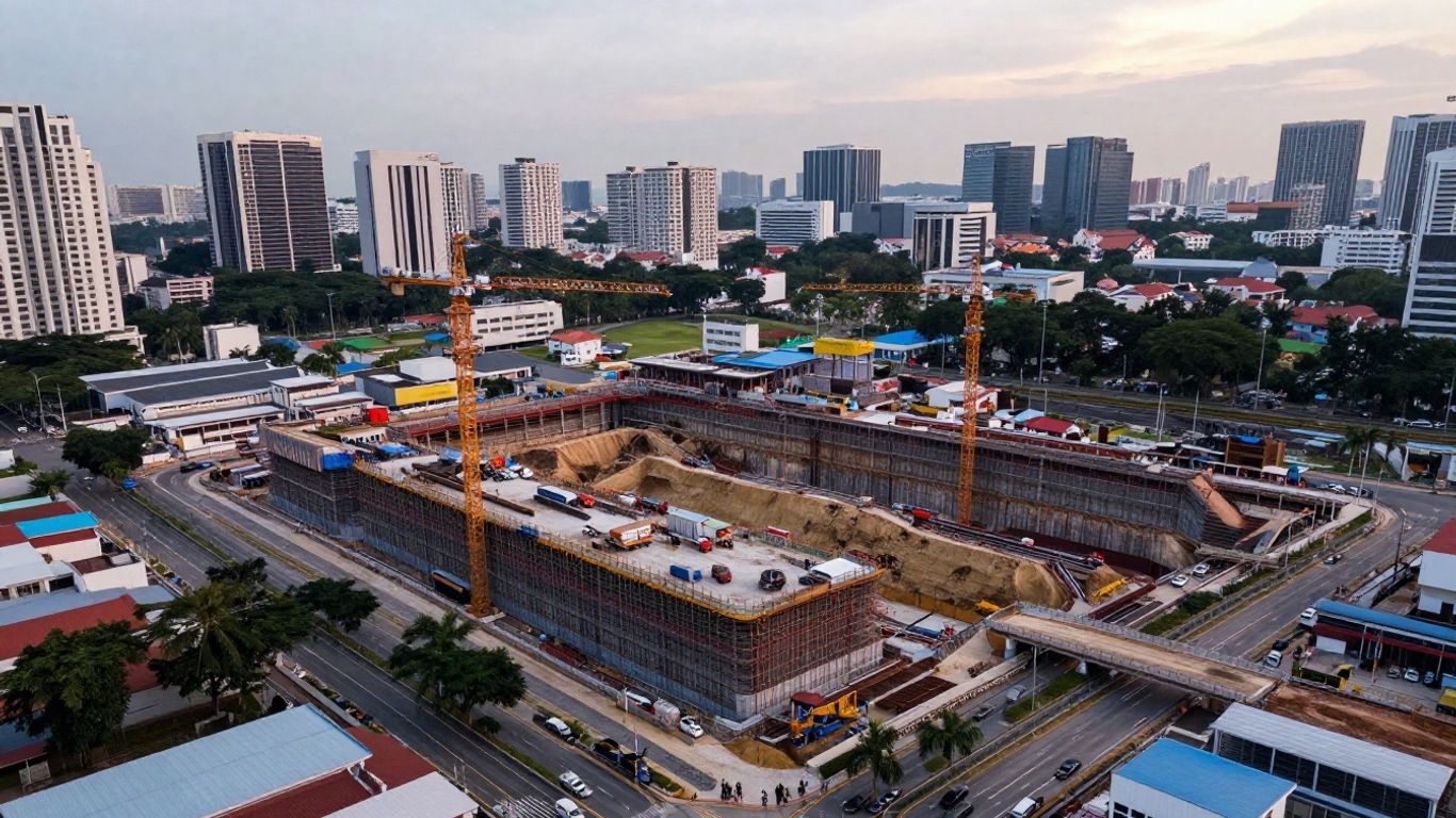
Deep excavation in Kallang Formation demands a ground model that accounts for soft marine clay, variable fill, groundwater, and time-dependent movement. ERSS design is strongest when geotechnical and structural decisions remain coordinated from investigation through construction.
- Build the geological and groundwater model before selecting the ERSS.
- Treat excavation staging, support installation, and monitoring as one system.
- Check basal stability, seepage, uplift, settlement, and overall stability together.
- Coordinate temporary works with the permanent basement and MEP interfaces.
- Use clear movement triggers and contingency measures during construction.
Establishing the ground model for Kallang Formation sites
Kallang Formation sites can change significantly over short distances. A useful ERSS design therefore begins with a three-dimensional understanding of fill, marine clay, sand, and deeper competent strata, rather than with a preferred wall type. The investigation must also describe groundwater conditions and the potential for spatial variability. This information becomes the common basis for the design decisions made by Geotechnical Engineers and Structural Designers.
Identifying marine clay, fill, and interbedded soil layers
Marine clay is often the controlling material for deformation, especially where a thick, soft stratum lies beneath fill or reclamation deposits. Fill may be loose, heterogeneous, or locally reinforced, while thin sand or silt seams can alter drainage and strength behavior. The geological model should distinguish these layers clearly and identify interfaces that could become seepage paths or planes of weakness.
A reliable interpretation is more than a sequence of borehole logs. It should connect observed strata between investigation points, record uncertainty, and flag areas where excavation behavior may differ from the average profile. The resulting model gives the ERSS team a defensible basis for selecting parameters and planning construction controls.
Planning boreholes, in-situ testing, and laboratory investigations
Singapore’s Building Control Regulations require comprehensive site investigation for deep excavation projects. A typical program may use boreholes at approximately 15–30 m spacing, supplemented by SPT, CPT, pressuremeter testing, laboratory classification, strength testing, and groundwater monitoring. The spacing and test mix should be adjusted for site size, excavation depth, nearby assets, and the variability suggested by earlier records.
Testing should answer design questions rather than simply increase the volume of data. Samples from the soft clay need to be protected from disturbance, and field observations should be reconciled with laboratory results. Early discussion between the investigation team and the designers helps ensure that the program can support both geotechnical interpretation and structural load assessment.
For a broader explanation of investigation scope and professional coordination, the geotechnical engineer guide is a useful complementary reference. Its principles fit the practical need to define services and deliverables before design begins.
Characterizing strength, stiffness, consolidation, and creep
Undrained strength is central to short-term excavation checks, but it is only one part of the model. Designers also need stiffness parameters for wall and ground movement predictions, compression and recompression behavior for settlement assessment, and consolidation and creep parameters for longer-term deformation. Stress history, including preconsolidation pressure and any effects of reclamation or previous loading, can materially change the response.
Parameter selection should reflect test quality, anisotropy, strain level, and the calculation method being used. A value that is suitable for a limit state check may not be suitable for a serviceability prediction. Sensitivity analyses are particularly helpful where the available data do not fully capture the range of plausible clay behavior.
Assessing groundwater, permeability, and artesian pressure
Groundwater is part of the ground model, not a separate construction note. Monitoring wells and standpipes should establish seasonal levels, hydraulic gradients, and possible pressure differences between sand seams and clay layers. Permeability estimates must be consistent with the soil profile, because a low-permeability clay layer may delay pressure dissipation while a more permeable seam can transmit water rapidly.
Artesian pressure deserves specific attention where deeper permeable strata are confined beneath clay. The design should consider how excavation, wall penetration, pumping, and recharge could change pore pressures. These conditions influence seepage forces, base stability, uplift, and the potential for settlement outside the site.
Defining ERSS design objectives and project constraints
ERSS is temporary works, but its consequences extend well beyond the excavation boundary. The design must retain the ground, maintain stability, control water, and protect neighboring structures and services while allowing the project to be built. In Singapore’s dense urban setting, movement criteria and construction sequence can be as decisive as nominal wall capacity. Aman Engineering Consultancy provides professional engineering consultancy services for projects requiring coordinated engineering design and endorsement, while the project team remains responsible for defining site-specific performance requirements.
Setting excavation depth, staging, and temporary support requirements
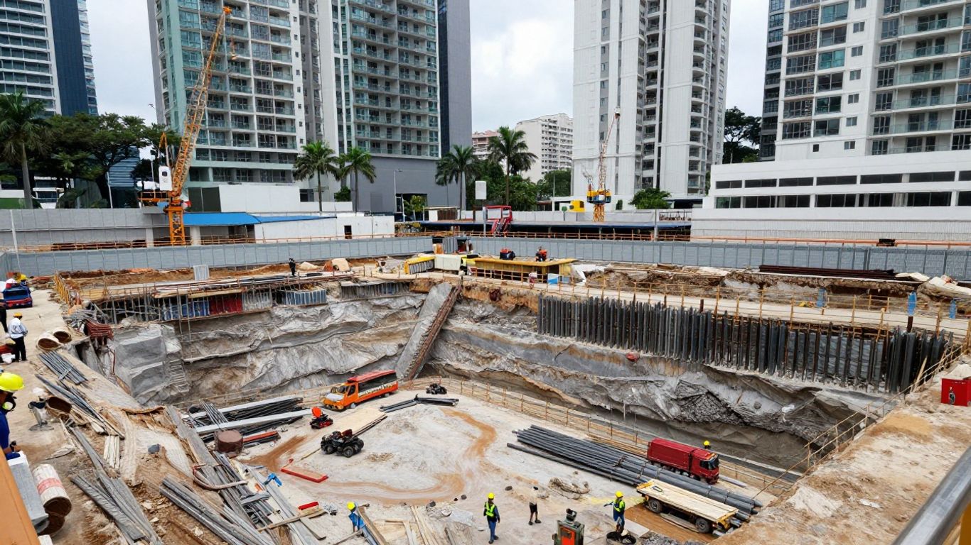
Excavation depth should be considered together with basement geometry, access, plant movement, and the sequence of support installation. Each excavation lift changes the stress state and the loads carried by the wall and supports. The temporary works design should therefore state the permitted stages, working levels, support preloads where applicable, and conditions for proceeding to the next stage.
Construction tolerances also belong in the design brief. Wall verticality, excavation overbreak, support installation timing, and local obstructions can all affect the intended load path. A practical ERSS scheme makes these requirements observable and workable for the contractor rather than leaving them as assumptions in the calculations.
Evaluating adjacent buildings, roads, utilities, and transit assets
A condition survey should establish the location, construction, foundation type, age, and sensitivity of adjacent buildings. Roads and pavements may be affected by settlement, while utilities require verified alignment, depth, condition, and consequence-of-failure assessment. Where transit assets or other critical infrastructure are nearby, the investigation and approval process may require tighter control of movement, vibration, and groundwater changes.
Utility information should be checked against electromagnetic locating, ground-penetrating radar, acoustic methods, records, and selective exposure where appropriate. The risk is not limited to direct contact with a service; ground movement can damage a buried pipe or cable even when the ERSS is physically clear of it.
Establishing movement limits for neighboring structures
Movement limits should be derived from the sensitivity and condition of each receptor, not adopted as a single site-wide number without explanation. The knowledge base identifies typical allowable ground settlement adjacent to excavations in Singapore as approximately 10–25 mm, depending on the sensitivity of nearby structures and utilities. Actual project limits may be more restrictive where brittle finishes, shallow foundations, or critical services are present.
The design should distinguish wall movement, ground settlement, angular distortion, vibration, and differential movement. It should also define how predicted values will be compared with observations. This creates a direct link between analysis, instrumentation, and decision-making during the works.
Coordinating ERSS requirements with the permanent basement design
Temporary supports may impose loads on slabs, walls, columns, transfer elements, and partially completed frames. The permanent structure must therefore be checked in temporary conditions, including the sequence in which it receives or releases ERSS loads. Cast-in items such as anchors, brackets, and embedments need design for both temporary and permanent load conditions.
Early coordination can avoid conflicts between struts, pile caps, reinforcement, waterproofing, openings, and construction access. The interface is a natural application for geostructural design, where earth behavior and structural response are considered together before construction fixes become expensive.
Selecting an earth retaining and support system
The retaining system should follow from the ground model and project constraints. No single ERSS type is universally suitable for Kallang Formation, because excavation depth, groundwater, neighboring assets, access, and permanent wall requirements may point in different directions. The design must verify ultimate and serviceability limit states under SS EN 1997-1, including overall stability, structural failure, hydraulic failure, and excessive deformation.
Comparing diaphragm walls, secant piles, contiguous piles, and sheet piles
Diaphragm walls are reinforced concrete walls constructed in situ and are well suited to very deep excavations, permanent basement walls, and situations requiring substantial water control. Secant pile walls use interlocking bored piles and can provide water-tightness for deep excavations up to about 30 m. Contiguous bored pile walls are installed with gaps and are more appropriate where the ground and groundwater conditions allow that arrangement.
Sheet piles can be effective for temporary excavations in soft soils, including works up to about 15 m deep, provided installation effects, embedment, groundwater, and adjacent sensitivity are acceptable. The comparison should include wall stiffness, joint performance, vibration, tolerances, removal or reuse, and the practicality of achieving the required toe level.
Choosing internal struts, rakers, ground anchors, or top-down construction
Internal struts provide direct restraint but can obstruct excavation, truck routes, and basement construction. Rakers may improve access in selected layouts, though they introduce concentrated reactions and require a suitable bearing arrangement. Ground anchors provide active support when rights, clearances, testing, and ground conditions permit; they are commonly used with other wall types rather than as a retaining wall by themselves.
Top-down construction can reduce the period during which the wall is unsupported and may allow the permanent slabs to act as support. Its benefits must be weighed against restricted excavation access, temporary openings, sequencing demands, and the need to coordinate concrete and MEP work early. The best option is the one that satisfies movement and stability requirements without creating an unmanageable build sequence.
Addressing wall embedment, basal stability, and seepage control
Embedment must provide adequate passive resistance and contribute to overall stability, not merely extend below the formation level by a convenient distance. Checks should consider soil strength, wall flexibility, surcharge, hydrostatic pressure, and the effects of staged excavation. In soft clay, basal heave can govern before the wall reaches its structural capacity.
Seepage control may require an embedded low-permeability wall, carefully treated joints, internal pumping, or a combination of measures. Hydraulic failure modes include piping, excessive uplift, and loss of effective stress near the base. The design should show how calculated water pressures will be managed during each construction stage.
Balancing constructability, site access, cost, and reuse potential
A theoretically efficient ERSS can become impractical if it relies on tolerances that the site cannot achieve. Plant size, spoil handling, slurry management, reinforcement cage installation, delivery routes, noise, vibration, and working hours should all be considered during option selection. Temporary works also need a realistic design life, commonly measured in months rather than decades, with attention to maintenance and exposure.
The lowest initial cost is not necessarily the lowest project cost. A system that simplifies support installation, reduces groundwater risk, or integrates with the permanent basement may reduce delay and remedial work. Constructability review should occur before the system is fixed, while alternatives remain genuinely available.
Analyzing excavation behavior in soft marine clay
Soft marine clay responds to excavation through a combination of immediate undrained behavior and slower drainage and creep. The analysis must reproduce the planned sequence, because the same final depth can produce different movements under different staging and support timing. Calculations should be checked against both limit states and serviceability criteria. Predictions are useful only when their assumptions remain visible to the construction team.
Modeling staged excavation and support installation
A staged model should represent initial stress conditions, wall installation, excavation lifts, support activation, slab construction where relevant, and changes in groundwater. Two-dimensional analysis may be appropriate for regular sections, while three-dimensional effects can matter near corners, ramps, cross-lots, irregular boundaries, and localized loads. The model should reflect realistic wall stiffness and support connection behavior rather than treating the excavation as a series of disconnected snapshots.
Construction records should be compared with the assumed sequence as work proceeds. If a support is installed late, a lift is over-excavated, or the wall differs from the designed geometry, the predicted response may no longer apply. This is why analysis and site control need to remain in communication.
Accounting for undrained strength and stress history
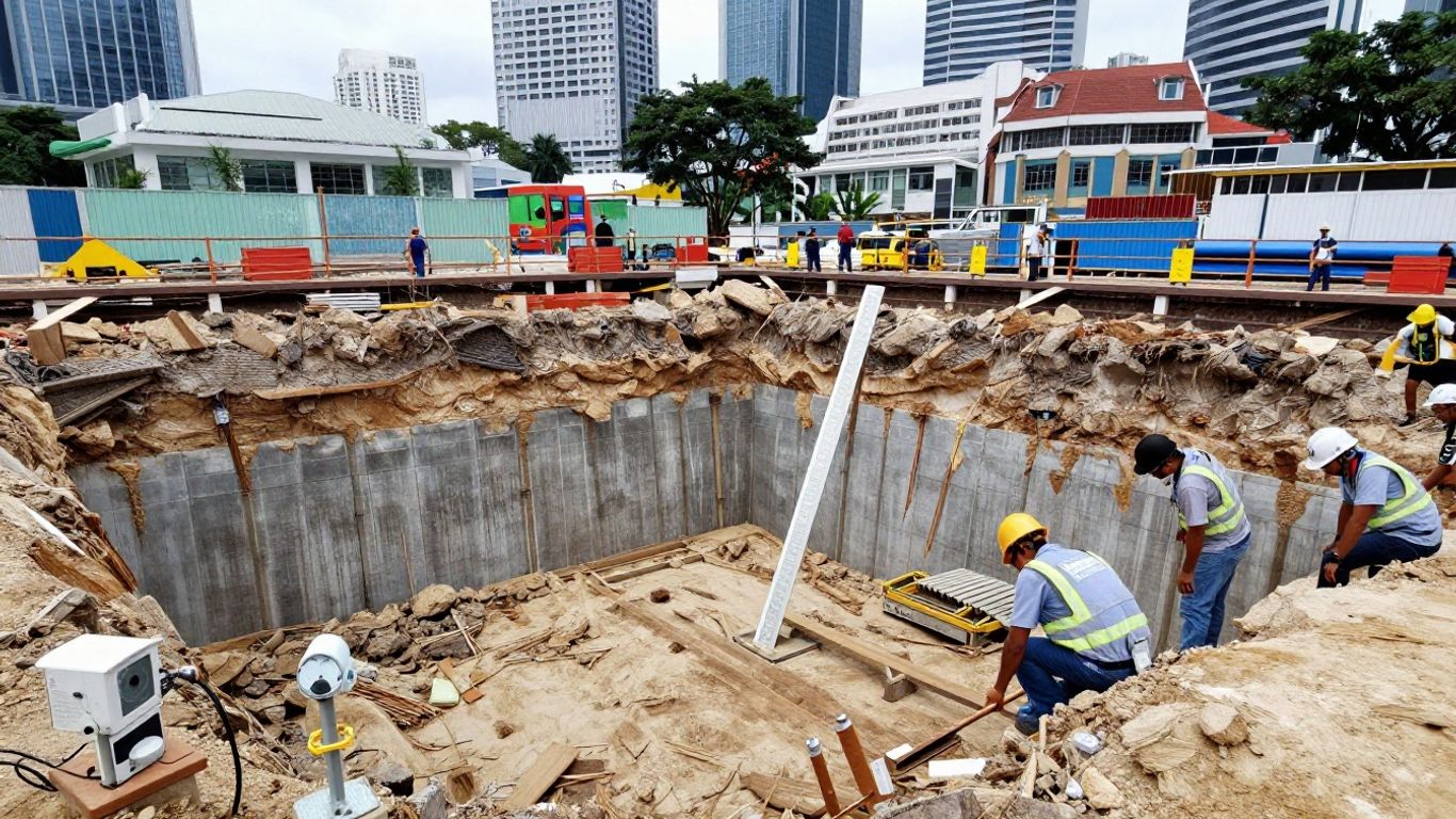
Short-term excavation behavior in saturated clay is commonly assessed using undrained strength, but the selected profile must account for variation with depth and stress history. Normally consolidated and overconsolidated zones can respond differently, particularly near the ground surface or where previous fills have imposed surcharge. Strength anisotropy and progressive failure should also be considered where the geometry or loading makes them relevant.
The designer should avoid treating a single average strength as representative of the entire site. Lower-bound values may be needed for critical basal or overall stability checks, while deformation analyses require parameters calibrated to the strain range of interest. Independent review of parameter selection is valuable when the consequences of movement are high.
Predicting consolidation settlement and time-dependent deformation
Excavation can change effective stress and pore pressure even when no pumping occurs. As excess pore pressures dissipate, surrounding clay may consolidate, and creep can continue after the main excavation stages. Settlement predictions should therefore consider construction duration, groundwater management, surcharge changes, and the time available for dissipation.
The result should be expressed as a range with clear assumptions rather than as an apparently exact forecast. Nearby foundations may respond differently from free-field ground, and buried utilities may be more sensitive to differential movement than to uniform settlement. Monitoring data can help refine the model as the project develops.
Checking basal heave, piping, uplift, and overall stability
Basal heave is a central concern where a deep excavation removes overburden from soft clay. The check should consider the undrained strength profile, excavation width, wall stiffness, support level, and the sequence of unloading. Piping and uplift become especially important where permeable layers or artesian pressures exist beneath the formation.
Overall stability should include the excavation, wall, supports, adjacent surcharge, and relevant groundwater pressures in a single credible failure mechanism. The ERSS must satisfy the applicable partial-factor design checks and demonstrate acceptable resistance to structural, geotechnical, and hydraulic failure. Results should be translated into construction hold points rather than left only in a design report.
Integrating geotechnical and structural design responsibilities
ERSS performance depends on a clear division of responsibility with active exchange of information. Geotechnical Engineers interpret ground behavior, water pressures, and soil-structure interaction, while Structural Designers verify the capacity and detailing of walls and supports. Neither discipline can close the design safely in isolation. Aman Engineering Consultancy’s positioning around adherence to ACI, BS, SS, and Eurocode requirements is relevant where project teams must coordinate regional standards and engineering endorsement.
How Geotechnical Engineers develop soil-structure interaction models
The geotechnical model translates soil parameters, groundwater, construction stages, and boundary conditions into predicted wall and ground response. It should explain which parameters control deformation, how support stiffness is represented, and where the model is least certain. Model outputs commonly inform wall bending, support reactions, ground settlement, pore pressure changes, and stability checks.
A model is not a substitute for engineering judgment. Its results need to be compared with site conditions, construction tolerances, and the behavior of similar soil layers. The soil and rock mechanics guide offers useful general context for how subsurface characterization informs retaining walls, foundations, and other infrastructure.
How Structural Designers verify wall, strut, waler, and connection capacity
Structural checks should use the actions and reaction envelopes supplied by the geotechnical analysis, including construction-stage reversals and localized effects. Wall reinforcement, struts, walers, brackets, anchor heads, and connections require checks for axial force, bending, shear, buckling, bearing, and robustness. Details must also accommodate tolerances and the possibility that forces are not distributed perfectly as an idealized model assumes.
Serviceability matters as well as strength. Deflection, cracking, durability, vibration, and connection slip can affect water tightness and neighboring movement. The final design should identify load combinations, material standards, inspection requirements, and any restrictions on field modifications.
Transferring excavation-induced loads into the permanent structure
As the basement is constructed, temporary supports may be removed or their function may be taken over by slabs and permanent walls. The load transfer path should be analyzed for each transition, including partially completed floors and temporary openings. Permanent elements may experience actions that are different from those considered in their final occupancy condition.
This transition should be reflected in drawings, method statements, and inspection points. Cast-in items and embedded plates need adequate capacity and access for installation. If the permanent system is expected to act as an ERSS support, that role must be explicit in the design and construction sequence.
Coordinating reinforcement, openings, waterproofing, and MEP interfaces
Coordination is especially demanding where support members cross basement circulation routes or occupy the space needed for services. Reinforcement congestion around strut seats, wall joints, penetrations, sleeves, and embedded items can create delays or compromise concrete quality. Waterproofing details should be resolved with the wall and joint design rather than added after structural drawings are complete.
A coordinated model and a controlled interface register can make these conflicts visible early. Each opening should have an owner, a structural review, and a waterproofing detail. This disciplined process is often less costly than field coring, unplanned trimming, or repairing a leaking joint.
Managing groundwater and environmental effects
Groundwater management must protect the excavation without transferring damage to neighboring land. Pumping can lower pore pressures beyond the wall, while insufficient control can destabilize the base or flood the work area. Environmental controls are equally practical: silty discharge, contaminated water, and uncontrolled runoff can delay work and create regulatory exposure. The design should connect hydraulic analysis, construction methods, and discharge management.
Designing dewatering and recharge strategies
The dewatering approach should follow the permeability structure and the wall’s cutoff performance. Possible measures include localized pumping, well systems, sump control, staged drawdown, or recharge where drawdown outside the site cannot be accepted. Pumping rates should be based on tested or justified hydraulic parameters, with allowances for rainfall, leakage, and construction variability.
Recharge is not automatically benign. It requires suitable locations, water quality controls, monitoring, and a clear understanding of how pressures will spread through permeable layers. The method statement should define startup, adjustment, standby equipment, and emergency response arrangements.
Controlling drawdown-induced settlement beyond the site boundary
When water levels fall outside the excavation, effective stress can increase in compressible layers and cause settlement. The risk is greatest where drawdown reaches soft clay, shallow foundations, buried utilities, or structures with limited tolerance. A predictive assessment should map the likely influence zone and identify receptors that need closer observation.
Mitigation may include better cutoff continuity, reduced pumping, staged drawdown, recharge, localized treatment, or revised excavation sequencing. The selected measure should be linked to trigger levels so that the response is not delayed until visible damage occurs. Groundwater observations outside the site are therefore as important as readings inside it.
Detailing water cutoffs, joints, and basement waterproofing
Water tightness depends on the whole system: wall material, panel or pile joints, base slab interfaces, penetrations, construction joints, and waterstops. Secant and diaphragm walls can provide useful cutoff performance, but workmanship, verticality, joint alignment, and defects still influence actual leakage. Details should identify inspection, repair, and acceptance requirements.
The permanent basement should have a coherent waterproofing strategy rather than isolated product details. Drainage layers, joint seals, kicker interfaces, penetrations, and sump arrangements must be coordinated with reinforcement and the intended maintenance regime. Mock-ups or trial details can expose constructability issues before repetitive work begins.
Managing discharge, silty water, and regulatory requirements
Discharge controls should address turbidity, suspended solids, pH, visible oil, and the receiving drainage system. Singapore’s Earth Control Measures framework includes requirements for erosion control planning, monitoring, maintenance, and water quality protection, with coordination involving agencies such as BCA, NEA, and PUB. Site teams should confirm the applicable approvals and discharge conditions before pumping begins.
A practical control plan includes treatment capacity, sampling locations, inspection frequency, rain-event response, and records of maintenance. Silty water should not be allowed to become an afterthought during a storm. Clear responsibility for pumps, settlement tanks, filters, and alarms helps keep environmental controls operational under pressure.
Verifying performance through monitoring and construction control
Monitoring is the feedback mechanism that tests whether the ground and structure are behaving as predicted. It should begin early enough to establish baseline conditions and continue through the critical excavation, support, permanent works, and dewatering stages. The objective is not simply to collect readings; it is to support timely engineering decisions. Good construction control turns measurements into actions.
Developing an instrumentation and monitoring plan
The monitoring plan should identify each receptor, instrument type, installation location, reading frequency, responsible party, data review process, and reporting route. Typical instruments may include wall inclinometers, settlement markers, precise leveling points, piezometers, load cells, building crack gauges, and survey prisms. Baseline readings should be collected before excavation or drawdown changes the existing state.
The plan must account for access, instrument protection, redundancy, and data quality. A sensor that cannot be read during a critical lift is not a dependable control. Monitoring locations should be reviewed when the excavation sequence or neighboring risk profile changes.
Tracking wall movement, ground settlement, pore pressure, and strut loads
Wall movement profiles can reveal whether the excavation is responding as expected at each support level. Settlement markers and building surveys show how ground response is transmitting beyond the wall, while pore pressure readings help distinguish mechanical movement from hydraulic effects. Strut loads provide a direct indication of support engagement, but they should be interpreted with temperature, installation timing, and local connection behavior in mind.
Trend, rate, and spatial pattern are often more informative than a single reading. A stable value that is close to a limit may be less concerning than a rapidly changing value well below it. Data should be reviewed against predicted envelopes and discussed with both design disciplines.
Establishing alert, action, and stop-work trigger levels
Trigger levels should be set before the relevant construction stage and should reflect instrument precision, baseline variation, predicted behavior, and receptor sensitivity. Alert levels prompt closer review, action levels require a defined mitigation or investigation, and stop-work levels require the affected activity to pause until the responsible engineers assess the condition.
A useful trigger framework can be organized around the following sequence:
- Confirm the reading, instrument condition, and recent construction activity.
- Compare the value and rate of change with the predicted response.
- Inspect the site, adjacent assets, supports, and groundwater controls.
- Implement the pre-agreed mitigation and revise the sequence if required.
This sequence prevents an isolated number from driving an unsuitable reaction while still preserving a rapid response. Trigger actions should be understood by the contractor, resident engineers, monitoring team, and approval authorities.
Applying observational methods, contingency measures, and authority coordination
The observational method is most effective when the design states what will be observed, what range is expected, and what action follows from each deviation. Contingencies may include additional strutting, reduced excavation lift height, temporary backfilling, pumping changes, recharge, local strengthening, or revised sequencing. These measures should be designed or pre-reviewed before they are needed.
Authority coordination is part of risk control where works affect public roads, utilities, drainage, or transit assets. Monitoring reports should be timely, traceable, and consistent with the approved method. Aman Engineering Consultancy can support projects requiring design and back-to-back engineering endorsement, but the project’s appointed professionals and authorities must retain clearly defined statutory and construction responsibilities.
Conclusion
Designing ERSS in Kallang Formation is an exercise in managing uncertainty as much as calculating capacity. A defensible ground model, carefully staged support system, integrated geotechnical and structural checks, controlled groundwater strategy, and responsive monitoring plan provide the best route to safe and buildable basements. When these elements are developed as one continuous process, the project team can protect surrounding assets while making informed decisions as the excavation progresses.
Frequently Asked Questions
What makes Kallang Formation challenging for basement excavation?
Kallang Formation may include soft marine clay, variable fill, interbedded permeable layers, and groundwater conditions that change across a site. These features can increase the risk of settlement, basal instability, seepage, and time-dependent deformation.
What investigation is typically needed before ERSS design?
A deep excavation investigation commonly includes boreholes, SPT or CPT, pressuremeter testing where suitable, laboratory classification and strength testing, and groundwater monitoring. The program should be tailored to the excavation depth, soil variability, and sensitivity of neighboring assets.
How is an ERSS system selected?
Selection depends on soil and groundwater conditions, excavation depth, movement limits, nearby structures and utilities, construction access, support sequencing, cost, and whether the wall will form part of the permanent basement.
Why is excavation staging important?
Each excavation lift changes earth pressures, pore pressures, and support reactions. Installing supports at the planned level and time helps control movement and ensures that the calculated load path remains representative of actual construction.
What are the main stability checks for a deep excavation?
The design should consider overall stability, wall and support capacity, basal heave, piping, uplift, seepage, excessive deformation, and other relevant hydraulic and structural failure modes under the applicable limit state framework.
How can drawdown affect neighboring properties?
Lowering groundwater can increase effective stress in compressible soils and cause settlement outside the excavation. The risk depends on the soil profile, pumping strategy, cutoff performance, distance, and sensitivity of nearby foundations and utilities.
What should an excavation monitoring plan include?
It should define baseline readings, instruments, locations, reading frequencies, data review responsibilities, predicted ranges, alert and action levels, stop-work criteria, reporting procedures, and contingency measures for abnormal behavior.