
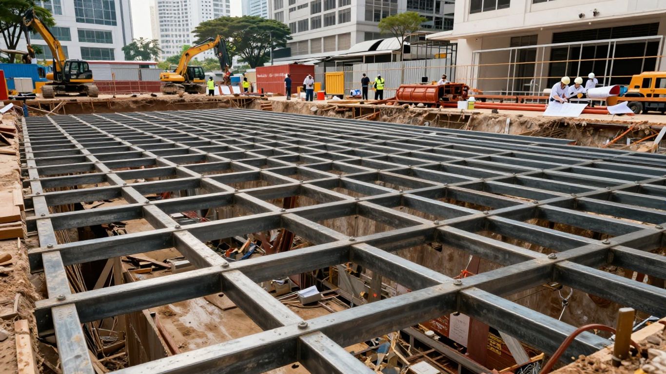
Key Takeaways
A temporary king post and strutting system is only as reliable as its design basis, connections, construction sequence, and site control. BCA approval depends on a coordinated package that explains both the engineering and how the system will be built.
- Define the ground, loading, geometry, and construction stages before detailing steel.
- Check member strength, buckling, connection capacity, bearing, and overall stability.
- Show installation, jacking, monitoring, and removal clearly in the design package.
- Coordinate temporary works with excavation, foundations, reinforcement, M&E, and permanent structures.
- Obtain the required professional review, endorsement, inspections, and approval records.
1. Understand the role of king post and strutting systems in temporary works
King posts and struts form part of a temporary support arrangement used to control movement during excavation or construction. Their design must account for the changing load path as soil is removed, support levels are installed, and permanent works begin to take over. The system is not simply a collection of steel members; it is a staged structural mechanism that must remain stable at every important stage.
When king posts and struts are used
King posts are commonly introduced where excavation support needs vertical or inclined load-carrying elements that can receive forces from walers, struts, or temporary platforms. Struts provide compression across an excavation, while associated walers distribute retaining-wall reactions into the strutting line. The arrangement may be selected where site boundaries, access, or adjacent properties make external support impractical.
The final choice depends on excavation depth, support-wall behaviour, available working space, groundwater, and the proposed construction sequence. Temporary works may be simple or complex, but the designer must remain competent for the scale and risk of the work.
How the system supports excavation and adjacent structures
Excavation changes the lateral pressure acting on the retaining system and can cause wall deflection, ground settlement, or movement of nearby structures. A strut transfers force across the excavation to another support line, while the waler spreads that force along the wall. King posts may collect vertical or local reactions and transfer them to bearing points, piles, or other designed supports.
The design should explain this path in plain terms. It should also identify what happens if a support is installed late, removed early, or affected by unexpected ground or water conditions. Movement control is a design objective, not merely an item for site monitoring.
Differences between internal strutting, raking struts, and walers
Internal strutting generally spans between opposing retaining walls or support lines and is effective where the excavation layout allows clear cross-site members. Raking struts are inclined and bear against a base, kicker, or other support, so their horizontal and vertical reactions need separate consideration. Walers are usually horizontal members fixed along the retaining wall to collect and distribute local reactions.
These components interact, but they are not interchangeable. An internal strut may be governed by buckling over a long unbraced length, while a raking strut may introduce substantial foundation or slab reactions. A waler may require checks for bending, local web effects, stiffeners, and connection eccentricity.
Temporary works responsibilities for the design team and contractor
The design team establishes the design assumptions, member capacities, connection details, sequence limits, and inspection requirements. The contractor is responsible for means and methods within the approved design, competent installation, setting out, temporary stability, and notifying the design team when actual conditions differ.
A clear responsibility matrix prevents small field decisions from becoming unreviewed structural changes. For projects requiring broad coordination, a full engineering design process can help connect investigation, analysis, drawings, authority submissions, and construction-stage responses.
2. Establish the design basis before preparing structural details
Good detailing begins with information, not steel sizes. The designer needs a dependable picture of the existing site, the soil and water conditions, the excavation sequence, and the loads that can reach the temporary system. If those inputs remain uncertain, the drawings should state the uncertainty and define the verification or hold point needed before construction.
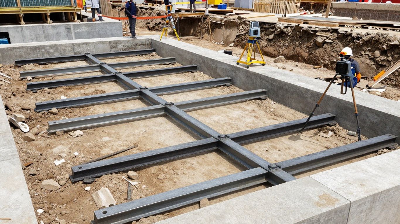
Site investigation and existing-condition information
Review the geotechnical report, retaining-wall design, borehole records, utility information, site survey, and available as-built drawings. Existing piles, slabs, walls, foundations, and buried services can govern where king posts and struts are placed. Field verification is especially important when old drawings are incomplete or when tolerances are tight.
The design basis should record the source and date of each significant input. It should also distinguish measured conditions from assumptions, since an assumed slab thickness or support level can materially change the load transfer arrangement.
Excavation geometry, construction stages, and support levels
Prepare the design around the actual sequence rather than a final excavation profile alone. Identify each excavation lift, the level at which walers and struts are installed, any jacking operation, and the point at which slabs or permanent frames provide replacement restraint.
Temporary conditions often govern. A partially installed strutting level, an open corner, or a removed strut can produce a different force pattern from the completed arrangement. Drawings should show these stages with enough dimensions for the site team to set out and inspect them.
Soil parameters, groundwater, and surcharge loads
The design should state soil unit weights, strength parameters, stiffness assumptions where movement is assessed, groundwater levels, drainage conditions, and the pressure model used. Surcharges may arise from cranes, stockpiles, traffic, temporary offices, materials, or neighbouring construction activities.
Water is not a secondary detail. Rising groundwater, leakage, or water accumulation can alter effective stresses and impose additional demands on retaining and temporary support systems. The calculations should identify sensitivity to these conditions and specify what site observation would trigger reassessment.
Adjacent buildings, roads, utilities, and site constraints
Map neighbouring foundations, basements, roads, pavements, rail or transit infrastructure, utilities, access routes, and property boundaries. The allowable movement may be controlled by a fragile adjacent building or a utility corridor rather than by the temporary steel itself.
The physical constraints should then be translated into design rules: maximum member projection, permitted drilling zones, lifting restrictions, access clearances, and monitoring points. A fabrication and storage facility is a useful example of how physical handling and fabrication constraints can affect the practical delivery of steelwork, although each project still requires its own site-specific plan.
Applicable Singapore Standards and BCA requirements
Confirm the applicable Singapore Standards, project specifications, geotechnical requirements, and BCA submission route at the outset. The knowledge base identifies SS EN 1990 for design basis, SS EN 1993 for steel structures, and SS EN 1991 actions including wind and execution-stage effects. BS 5975:2019 is also identified as a code of practice for temporary works procedures.
The submission should be consistent with the temporary works requirements relevant to the project and should address the Building Control Act, Building Control Regulations, applicable Codes of Practice, and any authority-specific conditions. Where the project is near sensitive infrastructure, additional requirements and monitoring obligations may apply.
3. Design the structural system for strength and stability
The analysis should follow the physical load path from retaining wall to waler, from waler to strut or king post, and finally into the bearing or foundation system. Each construction stage needs suitable load combinations and boundary conditions. A neat final model is not enough if it overlooks the unstable intermediate stage.
Load paths through struts, walers, king posts, and connections
Start by identifying where each reaction enters and leaves the system. A waler connection may receive a concentrated axial force, while a king post may carry combined axial force and bending from eccentric framing or temporary platforms. Gussets, stiffeners, bearing plates, and local wall components must be included in the force path.
The calculations and drawings should agree on member orientation, node locations, restraint assumptions, and connection eccentricities. Any load transferred into a slab, pile cap, ground beam, or kicker must be checked as part of the temporary system rather than treated as a site detail.
Axial force, buckling, bending, and second-order effects
Struts are often compression-governed, so effective length, bracing, imperfections, initial out-of-straightness, and connection restraint need careful treatment. Bending can arise from self-weight, eccentric contact, walers, construction loads, or misalignment. Second-order effects can increase demand where compression acts through a displaced geometry.
STAAD Pro includes built-in checks for BS, Eurocode, and Singapore standards, as well as P-Delta effects and geometric nonlinearity. Where it is used, the model should still be accompanied by engineering judgement, transparent assumptions, and checks that relate calculated forces to the actual temporary arrangement.
Base support, bearing, uplift, and load transfer at king posts
A king post does not become stable merely because its section capacity is adequate. Check the base plate, bearing surface, grout or packing, pile or foundation capacity, local concrete effects, sliding, uplift, and any eccentricity between the steel centroid and the support. Temporary bearing points must remain accessible for inspection and protected from disturbance.
Where a king post bears on soil or a temporary foundation, settlement and differential movement should be assessed. If a support depends on an existing slab or permanent element, the responsible engineer should confirm that the element can accept the temporary reaction without damage.
Global stability, local stability, and failure-mode checks
Review the whole arrangement for sway, racking, progressive loss of restraint, torsional response, overturning, sliding, and instability caused by an omitted or released member. Local checks should cover web crippling, flange bending, plate buckling, bolt group behaviour, weld capacity, and bearing at contact points.
The review is stronger when it is organised by failure mode rather than by software output alone. Independent design checking should examine the structural model, analysis methods, member sizing, connection design, detailing, buildability, and code compliance.
Serviceability limits for movement and ground deformation
Strength checks do not by themselves protect neighbouring buildings or utilities. Set movement, settlement, wall-deflection, vibration, and strut-load criteria with reference to the sensitivity of the surroundings and the approved monitoring plan. The design should state alert, action, and stop-work levels where these are required by the project.
Movement predictions should be compared with the construction sequence and updated observations. A small deviation detected early can be managed; an unexplained trend allowed to continue can remove the assumptions on which the temporary design was based.
4. Detail steel members and connections for safe construction
A temporary steel design must be buildable in a restricted excavation, often with limited lifting access and changing work fronts. Details should show how members arrive, fit, receive temporary restraint, and are later removed. The safest detail is usually the one that makes the intended sequence obvious to the people installing it.
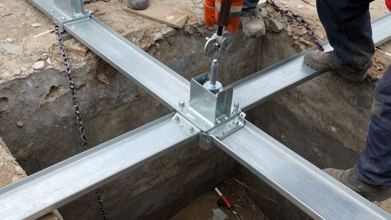
Member selection, splices, stiffeners, and fabrication tolerances
Select sections with regard to capacity, availability, handling weight, corrosion condition, and the required unbraced length. Splices should be located where forces and access permit efficient installation, with adequate allowance for fabrication and site tolerances. Stiffeners may be needed at concentrated waler, jack, or bearing reactions.
Temporary works are exposed to practical variations. Drawings should define critical dimensions, permissible tolerances, shim or packing arrangements, and the treatment of unexpected gaps. If members are fabricated for reuse, identification and inspection requirements should be stated clearly.
Gusset plates, end plates, bolts, and welded connections
Connection design should capture axial force, shear, moment, prying, block shear, net-section effects, weld access, bolt installation, and local member resistance. End plates and gussets must be proportioned to prevent unintended flexibility or force concentration. Connection details should identify bolt grades, hole types, tightening requirements, weld sizes, and inspection categories.
Tekla Structures can model bolts, welds, and connection details in a fabrication-oriented three-dimensional model. That level of information is useful only when it remains consistent with the calculations and approved drawings; a detailed model cannot compensate for an incorrect load path.
Jacking arrangements and preloading requirements
If jacking is required, specify the jack capacity, location, reaction path, sequence, target load or displacement, and release procedure. Preloading should not be described vaguely as “tighten as required.” The designer should state how the applied load is measured, recorded, and checked against the design intent.
The contractor should confirm that jacks, packing, bearing surfaces, and access arrangements are ready before the operation begins. Jacking can redistribute load to adjacent supports, so monitoring and hold points should cover the full system rather than the active strut alone.
Clash avoidance with excavation, reinforcement, and permanent works
Coordinate strut elevations and connection projections with excavation plant, reinforcement cages, pile caps, slabs, waterproofing, formwork, access stairs, and permanent columns. A member that is structurally adequate but blocks reinforcement or a required concrete pour is not a workable solution.
Model-based coordination can help identify conflicts before fabrication. A construction coordination approach is particularly valuable where several disciplines share a constrained work zone, but field dimensions and approved revision control remain essential.
Corrosion protection, access, lifting points, and removal provisions
Specify surface preparation, coating or other corrosion protection appropriate to the exposure period and site environment. Provide lifting points that are designed for the member weight and lifting configuration, along with safe access for bolts, weld inspection, jacking, and monitoring instruments.
Removal deserves the same attention as installation. Show the order of release, temporary restraints required before removal, exclusion zones, lifting arrangements, and the conditions under which permanent works may replace the temporary system.
5. Prepare drawings and calculations for BCA submission
A BCA-facing temporary works package should allow a reviewer to understand the proposal without reconstructing it from scattered sketches. Drawings, calculations, specifications, staging notes, and inspection requirements must tell one consistent story. The package should also identify the Professional Engineer responsible for the design and the limits of the approval.
Required contents of the temporary works design package
The package normally includes a design basis, site and geotechnical information, design criteria, structural analysis, member and connection checks, drawings, material specifications, construction sequence, inspection plan, monitoring requirements, and removal methodology. Include assumptions that affect safety, such as support stiffness, groundwater, surcharge, temporary restraints, and permissible installation tolerances.
Where relevant, add risk assessments, method statements, lifting information, instrumentation plans, and responses to earlier authority comments. A complete submission is easier to review and less likely to generate avoidable clarification requests.
Plans, elevations, sections, and typical connection details
Plans should establish grid references, member positions, support points, clearances, and setting-out dimensions. Elevations and sections should show levels, excavation stages, bracing planes, king-post embedment or bearing, and interfaces with retaining and permanent works. Typical details should be supplemented by project-specific details wherever forces or geometry differ.
Use consistent member marks across calculations, drawings, schedules, and fabrication information. Tekla Structures supports precise steel models and drawing production, including assembly, single-part, connection, and erection information, when the model is developed under controlled design data.
Temporary works calculations and design assumptions
Calculations should explain the structural idealisation, load cases, combinations, restraints, effective lengths, material grades, connection assumptions, and acceptance criteria. Include governing forces and reactions so that the site team and checker can relate the analysis to physical components.
A model printout without interpretation is difficult to audit. The calculation narrative should identify critical stages, sensitivity checks, and any condition that must be verified before proceeding.
Construction sequence, installation stages, and removal sequence
Show the sequence in drawings and method statements, including excavation lifts, support installation, jacking, inspection, loading restrictions, permanent-work integration, and removal. State which activities are prohibited before a specified hold point is released.
The sequence should also explain how temporary stability is maintained during transitions. For example, removing one strut may require a slab to have achieved a specified condition or a replacement restraint to be installed and checked first.
Design review, checking, and Professional Engineer endorsement
Arrange design review at the appropriate level for the project risk and regulatory route. The checking process should cover analysis, member and connection design, stability, detailing, buildability, sequencing, and code compliance. The Professional Engineer endorsement should be based on a complete and coordinated package, not on an isolated calculation sheet.
For complex or high-risk works, an independent checker may identify omissions in assumptions or construction stages that are not obvious to the original designer. Keep the checked and endorsed revision clearly identifiable throughout construction.
6. Coordinate the design with site C&S engineers and other disciplines
Temporary support is installed in a live construction environment, so coordination is part of structural design rather than a later administrative task. The design must align with the excavation sequence, concrete works, access, lifting, services, and permanent structure. Site C&S Engineers are often the first to identify when actual conditions no longer match the design basis.
Coordination with excavation, earth-retaining, and foundation works
Confirm retaining-wall stiffness, king-post or pile locations, excavation limits, berms, anchors, drainage, and foundation construction stages with the relevant teams. Strut reactions should be communicated to those designing the wall, pile cap, ground beam, kicker, or bearing support.
A change in excavation level or wall construction can alter force distribution. Coordination meetings should therefore review the next physical stage, not just the latest drawing register.
Interfaces with architectural, M&E, and permanent structural elements
Check penetrations, risers, plant access, fire routes, waterproofing, reinforcement congestion, slab openings, and permanent columns before fixing temporary member locations. M&E routes may be temporary, but they can still determine whether a strut can be installed or inspected safely.
Where the permanent structure replaces a temporary restraint, define the interface and required readiness criteria. Do not assume that a concrete element is available merely because it appears on a programme.
Site measurements, surveys, and verification of existing conditions
Survey control should establish retaining-wall positions, support elevations, slab levels, clearances, and deviations from the issued drawings. Measurements should be recorded in a form that can be reviewed by the design team and linked to the relevant revision.
If a measured condition differs materially from the design, stop the affected activity and obtain engineering direction. A quick field adjustment may be reasonable, but it should not become an undocumented redesign.
Resolving design changes, RFIs, and authority comments
RFIs should identify the affected member, stage, drawing, calculation assumption, and proposed site action. Responses need to state whether the change is accepted, rejected, or subject to revised calculations and drawings. Authority comments should be tracked to closure with clear evidence in the resubmission.
The same discipline applies to programme-driven changes. A request to remove a strut earlier or shift a waler for access can affect stability well beyond the local detail.
Roles of Structural Steel Designers and Site C&S Engineers
Structural Steel Designers translate the engineered arrangement into accurate member, fabrication, erection, and connection information. Site C&S Engineers verify setting out, installation quality, sequence, temporary stability, inspection records, and actual site conditions. Neither role should silently assume the other has checked a critical interface.
The strongest workflow has a clear review path between design, fabrication, erection, site supervision, and the Professional Engineer. It also benefits from an integrated construction solution when design and construction interfaces require close management, while retaining project-specific responsibility for engineering decisions.
7. Control installation, inspection, and approval during construction
The approved design only protects the project when the installed system matches it. Inspection should begin before steel arrives and continue through loading, jacking, monitoring, modification, and removal. Records provide evidence that the design conditions were followed and create a reliable basis for responding to movement or nonconformance.
Pre-installation checks for materials, dimensions, and setting out
Verify steel grades, section sizes, plate thicknesses, bolt certificates, weld consumables, coating condition, piece marks, and visible damage. Confirm survey points, support elevations, member lengths, connection orientation, lifting plans, and access before installation starts.
A practical pre-installation check should confirm:
- The latest approved drawings and method statement are available at the work front.
- Material identification and dimensions match the schedules and design assumptions.
- Bearing surfaces, packing, anchors, and connection locations have been surveyed.
- Lifting, access, exclusion zones, and temporary restraints are ready.
These checks catch errors before a member becomes difficult to move or before excavation proceeds to a less forgiving stage. Any discrepancy should be recorded and referred to the responsible engineer.
Welding, bolting, jacking, and connection inspection
Inspect fit-up, weld preparation, weld size, bolt installation, edge distances, plate contact, stiffeners, and tightening records in accordance with the specification. Jacking operations should be witnessed or otherwise controlled through calibrated equipment, recorded readings, and a defined release sequence.
Inspection should focus on the critical force path. A connection that looks complete may still have missing bolts, inadequate bearing, poor access, or a weld discontinuity that changes its capacity.
Monitoring strut loads, wall movement, and ground settlement
Monitoring should cover the quantities that reflect the design assumptions: strut loads, wall displacement, ground settlement, nearby building movement, groundwater, and relevant cracking or distortion. Readings should be taken at agreed stages and compared with alert and action levels.
Trends matter more than a single isolated reading. The site team should know who reviews the data, how quickly a response is required, and which activities are paused when thresholds are exceeded.
Managing nonconformances, modifications, and emergency conditions
A nonconformance may involve wrong steel, incorrect level, missing restraint, damaged coating, incomplete connection, excessive movement, or an unexpected obstruction. Protect the area first, preserve the relevant evidence, and notify the design and site management teams.
Emergency measures should be identified in advance where practicable, but improvised strengthening or cutting must not proceed without competent engineering direction. Revised calculations, sketches, inspection records, and approval should follow any accepted modification.
Documentation required for inspections, BCA PFI, TOP, or CSC stages
Maintain approved drawings, endorsed calculations, inspection and test plans, material certificates, weld and bolt records, jacking logs, survey results, monitoring data, nonconformance reports, variation approvals, and removal records. The exact documentation required depends on the project and authority process, so the submission and inspection plan should define the expected evidence.
For BCA PFI, TOP, or CSC-related stages, ensure records are organised, signed where required, and traceable to the relevant work. Clear close-out documentation helps demonstrate that temporary works were installed, controlled, and removed in accordance with the approved design.
Conclusion
A temporary king post and strutting system should be designed as a staged, coordinated structural system from investigation through removal. When Structural Steel Designers and Site C&S Engineers share a clear design basis, detailed load path, buildable connection information, disciplined inspection process, and complete BCA submission record, the temporary works are easier to approve and safer to construct.
Frequently Asked Questions
What is the purpose of a king post in temporary works?
A king post provides a vertical or inclined load-carrying element that can receive reactions from walers, struts, or temporary framing and transfer them to a designed support or foundation arrangement.
Are struts designed only for axial compression?
Struts are often compression-dominated, but bending, shear, eccentricity, self-weight, construction loading, imperfections, and second-order effects may also need to be checked.
Why is the construction sequence part of the structural design?
Loads and restraints change as excavation progresses, support members are installed, jacking occurs, permanent works become effective, and temporary members are removed. An intermediate stage may govern stability.
What information is needed before detailing a strutting system?
The designer generally needs reliable excavation geometry, geotechnical and groundwater information, retaining-wall data, surcharge loads, existing-condition surveys, adjacent-structure information, support levels, and the intended construction sequence.
What should connection drawings show?
They should identify member marks, plate sizes, bolts, welds, stiffeners, bearing and packing, tolerances, access requirements, inspection provisions, and any jacking or lifting arrangement that affects installation.
How are movements around an excavation controlled?
Movement is controlled through appropriate support stiffness and sequence, realistic soil and groundwater assumptions, monitoring of walls and ground, defined trigger levels, and timely engineering response to changing conditions.
Who endorses a temporary works design for submission?
The responsible Professional Engineer endorses the design in accordance with the applicable Singapore regulatory process. The project team should confirm the precise submission, checking, and inspection requirements for the particular work.