
Introduction
As-built verification protocols for permanent Earth Retaining and Stabilising Structures (ERSS) are mandatory post-construction inspections that must be completed before the Building and Construction Authority (BCA) grants Temporary Occupation Permit (TOP) or Certificate of Statutory Completion (CSC) approval in Singapore. These protocols confirm that every permanent retaining element – from diaphragm walls to ground anchors – was constructed in accordance with approved design specifications, and they form a non-negotiable component of the regulatory submission process.
This content covers post-construction structural inspections, wall verticality and tolerance audits, non-destructive testing methods such as sonic logging for diaphragm walls, photographic documentation standards, and the complete documentation package required for TOP and CSC applications. It does not address temporary ERSS systems that are removed after excavation, nor does it cover initial design submissions or geotechnical design methodology.
The target audience includes Professional Engineers (PEs), Qualified Persons supervising construction (QP(S)), developers, and contractors who bear direct responsibility for permanent ERSS completion and regulatory sign-off. Whether you are preparing your first TOP application or managing a complex multi-basement project, understanding these verification protocols is essential for avoiding costly delays and professional liability.
Direct answer: As-built verification protocols involve systematic structural inspections, dimensional surveys using total station and laser scanning, non-destructive testing (including crosshole sonic logging and core strength testing), ground anchor load verification, and comprehensive photographic documentation – all compiled into a certified submission package that confirms permanent ERSS elements match approved plans before regulatory sign-off.
After reading this article, you will understand:
-
The regulatory requirements governing permanent ERSS verification under the Building Control Act
-
Specific inspection methodologies including wall verticality audits and tolerance assessments
-
Non-destructive testing protocols for diaphragm walls, secant piles, and anchor systems
-
Documentation standards and professional certification requirements for TOP/CSC submissions
-
Common verification failures and practical solutions to avoid TOP/CSC delays
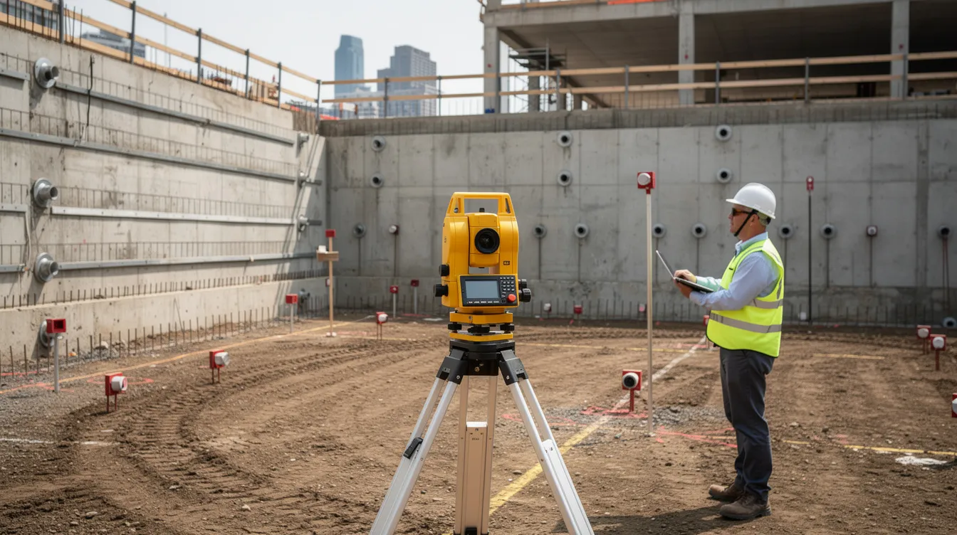
Understanding Permanent ERSS Verification Requirements
Permanent ERSS elements are structural systems that remain integral to a building’s stability indefinitely – they retain earth, resist lateral loads, and serve as basement walls or building envelope components long after construction is complete. Elements requiring as-built verification include diaphragm walls, secant pile walls, soldier pile walls with permanent facing, ground anchors designed for permanent service, and basement retaining structures connected to floor slabs. As-built verification protocols confirm the construction matches approved design plans by checking dimensions, material quality, structural integrity, and performance under loads.
Unlike temporary ERSS systems (such as temporary strutting removed after excavation), permanent ERSS must satisfy higher standards for durability, waterproofing, and long-term structural performance. This distinction drives fundamentally different verification requirements. As-built protocols include dimensional surveys and material quality assessments that verify every permanent element meets the structural design parameters approved by BCA.
Regulatory Framework for Permanent ERSS and Building and Construction Authority
The distinction between permanent and temporary ERSS elements determines which verification protocols apply. Temporary ERSS – covered under Temporary Submission (PTU) – are structural systems used only during earthworks and removed once permanent structures are in place. Permanent ERSS, by contrast, must comply with the full scope of structural plan submissions and as-built verification requirements because they continue to bear loads throughout the building’s lifespan.
Under the Building Control Act, structural plans for building works – including retaining structures, pile layouts, and geotechnical works – must be approved before construction begins. For permanent ERSS, this sits within wider plan approvals and overall building design compliance under bca requirements. Any deviations from approved plans discovered during as-built verification must be documented, assessed by a qualified person, and may require amendment submissions to BCA. The building control regulations require that as built plans for permanent ERSS be submitted post-construction as part of the TOP/CSC application package.
BCA’s ERSS requirements document specifies that record plans for permanent ERSS must include details of piled walls, structural sections, reinforcement layouts, and penetration depths, all endorsed by QPs and the accredited checker where applicable. ERSS submissions must include design calculations and plans, and BCA requires monitoring reports for ongoing ERSS works throughout the construction period. The ERSS Annex documentation – particularly Annex C-1 covering site inspection and approval records – must be completed progressively and forms part of the final verification package.
Excavation deeper than 1.5 m requires BCA submission, and localized excavation exceeding 2 m depth needs specific approval, reinforcing that permanent ERSS works are tightly regulated from design through completion. Submission for ERSS must follow CORENET procedures, and verification is mandatory before obtaining TOP or critical phase approvals. Some projects may also require clearance or coordination with the urban redevelopment authority within the wider development approval pathway.
Professional Responsibilities and Liability in Structural Safety
The QP(S), acting as the Professional Engineer for the structural discipline where applicable, carries primary responsibility for supervising permanent ERSS construction and certifying that completed works match the approved design. This includes inspecting construction at critical stages – embedded wall installation, strut level progression, temporary support removal – and confirming that wall sizes, penetration depths, reinforcement details, and material specifications comply with structural plans. QPs supervise construction to ensure adherence to approved plans, and deviations in construction must be documented and assessed by a qualified person.
Professional Engineers prepare and submit structural plans, and the PE responsible for the structural discipline must certify that installations comply with Singapore Standards. The structural PE verifies that permanent ERSS elements achieve specified structural safety margins through testing and inspection, and submissions affecting permanent structural systems may also involve a registered architect where material interfaces with design scope arise. PEs must certify structural integrity testing results that verify concrete strengths and material compliance.
Where required, the accredited checker (AC) and AC(Geo) review the as-built documentation independently, endorsing that permanent works align with design assumptions and geotechnical parameters. All professionals bear liability for non-compliance that results in safety risk or regulatory rejection. A Certificate of Supervision is required for TOP applications, signed by the QP(S) confirming all permanent ERSS works were constructed per the approved design. Architectural interfaces should also be assessed where permanent ERSS forms part of the basement wall, façade line, or other elements affecting compliance.
These professional responsibilities connect directly to practical verification methodologies – the testing, surveying, and documentation work that generates the evidence supporting each certification.
Verification Procedures and Testing Methods
With the regulatory foundation established, verification procedures translate statutory requirements into systematic inspections and tests applied to every permanent ERSS element. The project team must coordinate these activities carefully, as inadequate verification at any stage can result in TOP/CSC rejection.
Structural Dimension and Tolerance Verification
Wall verticality surveys are among the most critical dimensional checks for permanent ERSS. After diaphragm wall or secant pile construction, surveyors use total station instruments, theodolites, or 3D laser scanning to measure wall face alignment against design coordinates. BCA Advisory Note 1/09 establishes allowable wall deflection limits that vary depending on site classification – greenfield versus constrained urban sites. Typical verticality tolerances are expressed as ratios such as 1:500 (1 mm deviation per 500 mm of wall height), though exact limits depend on the approved design and boundary conditions.
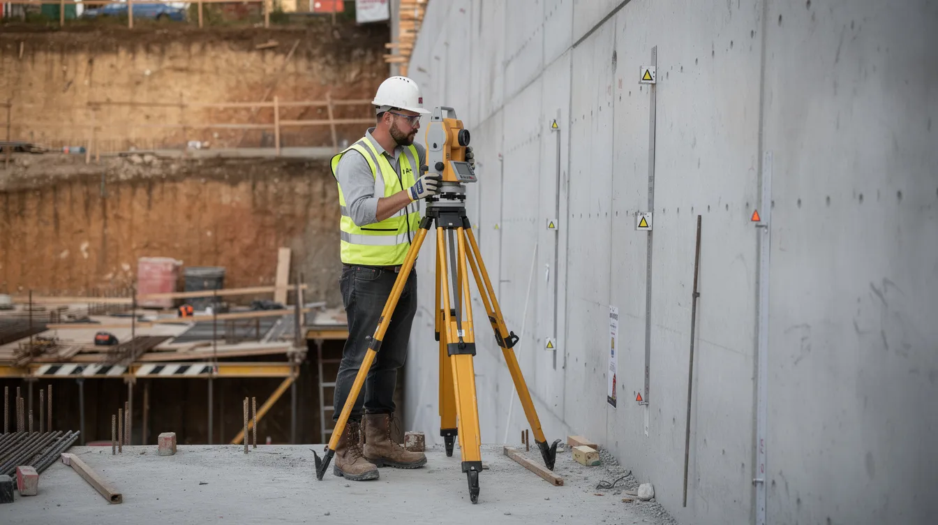
Penetration or embedment depth verification confirms that embedded piled walls extend into underlying competent strata as specified in the structural design. Advisory Note 1/09 explicitly requires the QP(S) to verify that “as-constructed embedded piled wall sizes and penetration depths are in accordance to my design.” Deviations beyond design tolerance – even minor shortfalls in toe penetration – require engineering assessment and potentially remedial works such as supplementary grouting.
Wall thickness verification uses core sampling (semi-destructive) and sonic testing to confirm concrete section dimensions. For diaphragm walls, panel width, joint detail, and toe detail are critical measurements. Typical thickness tolerances are ±50 mm or ±5% of nominal dimension, though project-specific design calculations may impose tighter limits. Reinforcing steel layout, bar size, spacing, and concrete cover are verified against as built drawings through a combination of physical measurement and electromagnetic cover meter scanning.
Non-Destructive Testing Protocols
Crosshole sonic logging (CSL) is the primary non-destructive testing method for assessing internal integrity of diaphragm wall panels. The procedure involves placing access tubes within the wall during construction, then transmitting ultrasonic pulses between tube pairs after concrete curing. Travel time variations and signal anomalies identify internal defects including voids, honeycombing, soil inclusions, and inadequate tremie joint concrete. Non-destructive testing identifies defects in critical structural elements that visual inspection alone cannot detect.
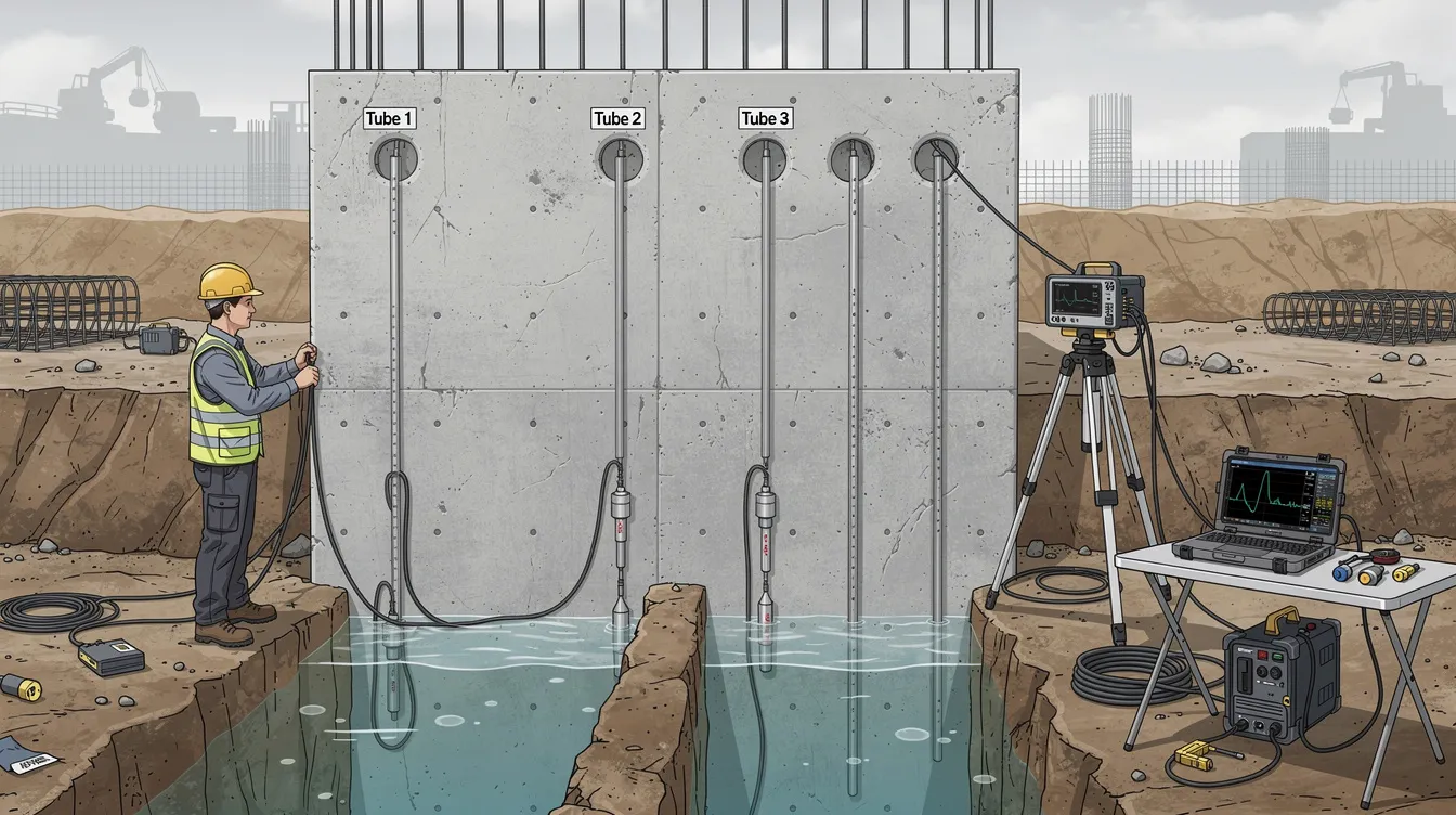
The SAC Accreditation Scheme for non-destructive testing specifies that diaphragm walls should undergo sonic logging, toe coring, and core sample testing of the top 3 m from cut-off level. Industry practice typically requires sonic logging at all tremie joint zones between panels and at locations identified as high-risk during construction. Interpretation of CSL results requires specialist expertise – anomalies must be evaluated against acceptance criteria defined in the project specifications, and failed zones may require remedial grouting or structural reinforcement.
Core strength testing confirms concrete compressive strength meets the specified characteristic strength (commonly 40 MPa or higher for permanent retaining structures). Structural integrity testing verifies concrete strengths and material compliance through laboratory testing of extracted cores. Typically, three or more cores are extracted at the wall toe and near the cut-off level, with results compared against design calculations and Singapore Standards requirements.
Ground anchor load testing verifies permanent anchor capacity through proof loading. Each permanent anchor undergoes load testing to confirm anchorage bond performance, with load-displacement plots recorded and compared against design criteria. Inspections also cover corrosion protection systems, anchor head condition, and load cell readings – critical for long-term structural safety of anchored retaining systems. Where the project includes a lightning protection system, testing and documentation should align with CSC 03 PE certification requirements for lightning protection compliance, as part of broader bca csc csplp documentation where applicable. Retaining systems require monitoring due to their impact on stability and adjacent structures.
Geotechnical instrumentation reviews assess data from inclinometers and piezometers installed during construction, verifying that ground movement and groundwater conditions remained within acceptable thresholds throughout the ERSS construction sequence. Calibration of monitoring thresholds must occur before proceeding with construction stages to ensure meaningful data collection.
Visual and Photographic Documentation
Systematic photographic documentation is a mandatory component of as-built verification. Photography must capture entire wall surfaces, construction joints (panel joints for diaphragm walls, overlap zones for secant piles), reinforcement layouts before concrete placement, base and footing water stops, and connections between permanent ERSS and basement floor slabs.
All photographs must include scale references, date stamps, and location identifiers. Defect documentation – cracks, leaks, deformations, surface irregularities – requires close-up photography with annotations describing the defect nature, extent, and subsequent remedial actions. The site inspection record maintained by the QP(S) tracks every defect through identification, assessment, remediation, and re-inspection.
These visual records become part of the permanent project documentation and serve as evidence supporting the QP(S) certification that all permanent ERSS elements were constructed in compliance with the approved design. As-built verification contributes to safety by confirming structural performance under loads, and photographic evidence provides the verifiable record.
The testing and documentation methods described above must be organized into a coherent implementation protocol aligned with BCA’s submission requirements and TOP/CSC application timelines.
Implementation Protocol and Documentation Requirements
Translating verification methods into a systematic process requires careful sequencing, clear responsibilities, and thorough documentation standards. The project team must coordinate verification activities to align with both construction completion milestones and BCA’s processing timelines – BCA processes TOP applications within 7 working days, and express TOP applications can be processed in 1 working day, but the QP must submit documents 3 days before inspection.
Step-by-Step Verification Process
Verification activities must be planned and executed relative to construction completion and the TOP application timeline. Qualified Persons (QPs) must submit applications to BCA with complete supporting documentation, making early planning essential.
-
Pre-verification planning: Before permanent ERSS construction reaches completion, the project team develops a verification plan identifying all structural elements requiring inspection (wall panels, anchors, slab connections), agreed tolerances per approved design, selected testing methods (CSL, core sampling, load tests), NDT specialist engagement, and instrumentation review schedule. This plan should reference the site investigation report, approved design data, and information modelling records so verification criteria and as-built checks match the original geotechnical parameters.
-
Progressive construction-stage inspections: During construction, the QP(S) conducts site inspections at critical stages – after embedded wall installation, at successive strut levels, and before excavation proceeds to the next level. The inspections and tests must be carried out progressively and recorded before final compilation. The ERSS Annex C-1 (site inspection and approval records) is filled progressively. Monitoring data from inclinometers, piezometers, and settlement markers is reviewed against threshold values at each stage. BCA requires monitoring reports for ongoing ERSS works throughout this period.
-
Final verification after permanent elements are complete: Once all ERSS components are permanently constructed – walls, anchors, permanent facing, basement slab connections, waterproofing – the complete suite of verification activities is executed: dimensional surveys (verticality, thickness, penetration), NDT (sonic logging, core strength testing), anchor load tests, material compliance tests, and comprehensive photographic documentation.
-
Assessment and remediation: Where test results or dimensional checks exceed allowable tolerances, the structural PE assesses structural consequences, proposes remedial works (supplementary grouting, additional reinforcement, local re-profiling), updates as built drawings, and submits amendments to BCA if required. All corrections must be certified by both the PE and QP(S), with remediated areas re-tested and re-photographed.
-
Documentation compilation and QP sign-off: All as built plans, test reports, certificate of supervision, monitoring records, and remediation documentation are compiled into the submission package. The QP(S) signs the Certificate of Supervision of Building Works and Declaration confirming permanent ERSS compliance. TOP applications require clearances from multiple technical agencies and relevant agencies beyond BCA.
-
Submission to BCA: Final as-built documentation ensures compliance with design and statutory requirements. The complete package – including as built plans, test reports, professional certifications, and monitoring summaries – is submitted with the TOP/CSC application. Regulatory bodies require proof of compliance before issuing completion certificates. BCA requires Building Plan submissions before construction starts, and coordinated plan approvals increasingly use digital information modelling workflows; at close-out, the as-built submission must still satisfy BCA requirements by confirming what was built matches what was approved.
Documentation Standards Comparison for Structural Plan Submissions
Different permanent ERSS types require tailored verification approaches. The following comparison helps practitioners identify applicable requirements for their specific system:
|
Criterion |
Diaphragm Walls |
Secant Pile Walls |
Soldier Pile with Permanent Facing |
|---|---|---|---|
|
Primary NDT Method |
Crosshole sonic logging at tremie joints and panel zones |
Sonic coring of pile toes; CSL at interlock zones |
Ultrasonic testing of steel sections; concrete facing cores |
|
Verticality Tolerance |
Typically 1:500 or per approved design |
Per pile layout plan specifications |
Per structural design; facing alignment ±10 mm |
|
Core Sampling |
Top 3 m from cut-off level + toe cores |
Representative piles per project specifications |
Permanent concrete facing cores |
|
Penetration Depth Check |
Mandatory – toe must reach design depth |
Pile toe level verified against boring logs |
Soldier pile embedment verified against geotechnical parameters |
|
Joint/Overlap Verification |
Panel joint integrity via CSL + visual |
Overlap/interlock measurement + waterproofing check |
Connection details between piles and facing |
|
Anchor Testing |
Proof load test if anchored design |
Proof load test if applicable |
Proof load test for all permanent anchors |
|
Documentation Frequency |
Every panel documented; CSL at all tremie joints |
Every pile documented; representative NDT |
All piles + full facing inspection record |
|
Waterproofing Verification |
Joint waterstop inspection + leak testing |
Interlock seal inspection + membrane check |
Facing-to-structure seal verification |
Verification requirements may vary for newer systems such as mass engineered timber interfaces or hybrid permanent works, although the core structural sign-off principles remain the same.
Practitioners should reference their project-specific structural plans and BCA submission requirements to confirm exact testing frequencies and tolerance limits, as design calculations may impose stricter criteria than general guidelines. The accredited checker must endorse as-built plans for projects where AC involvement is mandated.
Common Challenges and Solutions
Several recurring verification issues cause delays in TOP/CSC approval. Understanding these challenges enables the project team to implement preventive measures during construction rather than discovering problems at the submission stage.
Inadequate Non-Destructive Testing Coverage
A common failure involves insufficient sonic logging coverage – too few panels tested, critical tremie joint zones missed, or failure to test toe regions where access is difficult. This leads to BCA requesting additional testing, delaying the submission process.
Solution: Develop a systematic sonic logging grid during pre-verification planning that covers all tremie joint zones and at least the minimum representative sample required by SAC accreditation standards. Engage NDT specialists early – ideally during piling works – to ensure access tubes are properly installed and testing locations are agreed before concrete placement. Document the testing plan as part of structural plan submissions so the scope is clear to all parties.
Tolerance Exceedances and Remediation
Wall verticality deviations, penetration depth shortfalls, or thickness variations are often discovered late due to poor coordination between surveying and construction teams, or inadequate progressive monitoring during construction.
Solution: Implement progressive survey checks at each construction stage rather than waiting for final verification. Use laser scanning technology to create 3D as-built models that can be compared against approved design geometry in real time, since better construction practices improve coordination between surveying, structural, and site teams when deviations are detected early. When exceedances are identified, conduct immediate engineering assessment to determine whether the deviation affects structural safety. Document all remedial works – supplementary grouting, additional reinforcement, re-profiling – with updated as built drawings and re-testing evidence. Early detection through systematic structural engineer inspections significantly reduces remediation cost and schedule impact.
Incomplete Documentation Packages
Missing endorsements by the accredited checker, absent photographic logs, as built plans that don’t reflect actual construction, unclear laboratory test reports, or missing professional certifications are among the most frequent causes of TOP/CSC application rejection. Outstanding issues in documentation can delay BCA processing beyond the standard 7-working-day timeline.
Solution: Maintain a verification checklist aligned with BCA’s CSC application requirements from project inception. Complete packages may also need supporting documentation tied to pollution control or energy efficiency submissions where those approvals apply to the overall project. Keeping the record complete across building and development approvals helps prevent unrelated clearance gaps from holding up CSC. Accumulate documentation progressively during construction – photographic logs taken at each critical stage, test reports filed as they are received, monitoring records compiled weekly. Coordinate with the QP(S) and AC for mid-construction reviews rather than end-of-project sign-off marathons. Ensure all certificates bear the professional’s full name, registration number, date, and stamp. Final as-built documentation ensures compliance with design and statutory requirements and must be complete before the submission deadline.
Conclusion and Next Steps
Successful as-built verification of permanent ERSS requires systematic planning from pre-construction, disciplined execution of dimensional surveys and non-destructive testing at every critical stage, and meticulous documentation that demonstrates compliance with approved structural plans. The verification process is not merely a regulatory formality – it confirms that permanent retaining structures will perform safely throughout the building’s operational life, protecting building owners, adjacent properties, and public safety.
To ensure your permanent ERSS verification proceeds without delays:
-
Develop a project-specific verification plan during the design phase that identifies all permanent ERSS elements, testing methods, tolerance criteria, and documentation requirements
-
Engage qualified NDT specialists early – before piling works commence – to coordinate access tube installation and testing schedules
-
Implement progressive verification with dimensional surveys, monitoring reviews, and photographic documentation at each construction stage rather than deferring all checks to completion
-
Establish a documentation management system using verification checklists aligned with BCA’s TOP/CSC submission requirements, and confirm all professional certifications are current
-
Coordinate submission timelines to ensure documents are submitted at least 3 days before scheduled BCA inspection, with clearances from all relevant technical agencies secured in advance
Related topics worth exploring include ongoing monitoring requirements for permanent ERSS after building occupation, periodic structural inspection obligations for retaining structures, and the evolving role of BIM in regulatory compliance. CORENET X integrates BIM for streamlined regulatory submissions, and BCA targets 80% BIM adoption in the construction industry – permanent ERSS integrated into the building structure must now be modelled in coordinated BIM submissions, a trend that will increasingly shape how as-built verification data is structured and submitted. BIM enhances project efficiency and collaboration among professionals, and BCA promotes BIM to improve sustainability in construction.
Additional Resources
-
BCA Advisory Note 1/09 – Foundational regulatory reference for ERSS wall deflection limits, instrumentation requirements, monitoring protocols, and allowable tolerances by site classification
-
BCA ERSS Requirements Document – Submission requirements for permanent ERSS structural plans, record plans, and professional certifications
-
SAC Accreditation Scheme for Non-Destructive Testing (CT 32) – Technical criteria for sonic logging, toe coring, and core sample testing of diaphragm walls
-
BCA Site Management Data Standards (Draft) – Emerging digital submission standards including mandatory data fields for ERSS construction stages, monitoring readings, and as-installed element adequacy
-
Complete Guide to BCA Submissions – Comprehensive overview of Building Plan, Structural Plan, and related approval processes in Singapore