
Introduction
Finite element modeling in PLAXIS 2D and PLAXIS 3D is the primary method structural engineers use to demonstrate that permanent earth retaining structures meet the Building and Construction Authority’s design and safety requirements for deep excavations in Singapore, and the best practice for BCA permanent ERSS reviews is to calibrate the Hardening Soil with Small-Strain Stiffness (HSs) model with Singapore soil data, apply the correct drained or undrained analysis at each excavation stage, validate results against hand calculations, and control mesh quality, boundary conditions, and construction sequencing. ERSS systems resist lateral earth and water pressures, and finite element modeling allows engineers to quantify wall deflections, strut forces, ground settlement, basal heave, and pore-water pressure changes across staged construction sequences. BCA regulates excavations deeper than 6 meters in Singapore, classifying them as Geotechnical Building Works (GBW) that require involvement of a Qualified Person (Geo) and an Accredited Checker.
This article focuses on PLAXIS 2D and 3D modeling workflows for permanent ERSS design, HSs soil model calibration, selection between drained and undrained analysis types, the common FEA errors Accredited Checkers flag during BCA structural plan reviews, and the FEM documentation needed for BCA submission. It is written for structural engineers, geotechnical consultants, and developers handling basement excavation and tunneling projects in Singapore where a BCA-compliant permanent ERSS design must be demonstrated clearly and defensibly. The scope here is review-ready modeling practice for authority submission and design checking, not a general introduction to geotechnical theory or software basics.
For BCA review, a PLAXIS model is acceptable only when it reflects Singapore ground conditions, matches the actual construction sequence, and produces outputs that can be checked independently against simplified calculations and engineering judgment. That matters in practice because permanent ERSS approval depends on credible prediction of soil-structure behavior, and weak modeling assumptions can delay structural plan clearance or increase excavation risk.
After reading this article, you will be able to:
-
Implement HSs model calibration using Singapore-specific soil parameters and laboratory test data
-
Select between PLAXIS 2D and 3D analysis based on project geometry, BCA submission stage, and Accredited Checker requirements
-
Identify and avoid the mesh, boundary condition, and construction sequence errors that Accredited Checkers reject
-
Prepare FEM documentation packages that satisfy BCA’s “Design Considerations for ERSS” form and structural plan submission guidelines
-
Choose between drained and undrained analysis for each excavation stage based on soil permeability and loading rate
Understanding Finite Element Modeling for Geotechnical Engineering in ERSS Design
The finite element method divides the soil mass and structural elements into discrete elements that approximate continuous media. Each element follows a constitutive soil model that defines how it responds to stress changes: small-strain stiffness, stiffness degradation under increasing strain, yield criteria, and post-yield plastic behavior. For ERSS design, this approach captures the complex interaction between retaining wall movement, soil resistance, water pressure, and structural loads that simpler limit equilibrium methods cannot resolve.
Permanent earth retention systems require accurate soil-structure interaction modeling because excavation changes the stress state of surrounding soil through every construction stage. As excavation proceeds, lateral earth pressures redistribute, strut or anchor forces change, and ground deformation propagates toward adjacent structures. Soil stiffness influences wall deflection in excavation designs, and the finite element method tracks these coupled effects across the full construction sequence.
PLAXIS 2D models soil behavior under various loading conditions; it allows detailed geotechnical modeling of soil layers and conditions, including groundwater flow and pore pressure distribution. The software performs limit equilibrium analyses for slope stability and supports multiple soil models, from Mohr-Coulomb to advanced options like the Hardening Soil model. Users can select from various soil models, and interface elements allow realistic slip and separation between structure and soil. Modeling requires precise definition of initial stress states and soil parameters.
PLAXIS Software Fundamentals
PLAXIS 2D handles plane strain analysis for retaining systems with uniform cross-sections along their length, such as long diaphragm walls or sheet piles. PLAXIS 3D extends this capability to irregular geometries where corner effects, non-uniform surcharge, or asymmetric soil conditions affect behavior. Both versions support the Hardening Soil with Small-Strain Stiffness model, which adds a small-strain overlay to the standard Hardening Soil framework through two additional parameters: reference initial shear modulus (G₀ʳᵉᶠ) and threshold shear strain (γ₀.₇) at which secant stiffness reduces to 70% of the small-strain value.
Effective element selection includes using plate elements for retaining walls and embedded beam elements for efficient modeling of pile groups and soil nails. Interface elements between structural components and soil control friction, normal stiffness, and separation behavior. These interface properties directly affect predicted wall movement and soil pressure distribution. Calibrate stiffness parameters against high-quality laboratory or field data before running production analyses.
BCA Submission Requirements for ERSS
The Building and Construction Authority structural plan submission guidelines require site investigation (SI) reports with standardized AGS(SG) data format, evaluation of geotechnical characteristic values to Eurocode 7, and observational method implementation for groundwater control in deep excavations. Eurocode 7 is the dominant standard for ERSS design in Singapore.
BCA mandates risk assessments for excavations deeper than 6 meters and requires involvement of a QP(Geo) and Accredited Checker (AC), with AC(Geo) for excavations classified as GBW. The Design Considerations for ERSS form (April 2024) requires the QP(D) and AC to confirm that soil parameters selection, water pressures and seepage, both drained and undrained conditions, structure embedment against toe kick-out, and sensitivity analyses have all been addressed. BCA guidelines enforce a two-set-of-eyes principle for excavation safety, with the AC independently reviewing the designer’s work. Surcharge loads of at least 10 kPa, varying groundwater conditions, and varying loads during construction must be included.
For CORENET X submissions, temporary ERSS elements that are not part of permanent works need not be included in the BIM model. ERSS integrated into permanent structures must be included. BCA mandates the AAA (Alert, Alarm, Action) system for critical excavation parameters, and the AAA system monitors wall deflection and ground settlement throughout construction. BCA’s alarm levels must link to ultimate design capacity.
These documentation requirements shape what the finite element analysis model must produce: wall forces, strut loads, deflection profiles, base heave predictions, and sensitivity study results that directly populate the BCA submission forms.
PLAXIS 2D vs 3D Applications in ERSS Design
With the FEM fundamentals and BCA requirements established, the next decision is whether to model in two or three dimensions. This choice affects computation time, result accuracy, and what the Accredited Checker will accept.
2D Plane Strain Analysis Applications
PLAXIS 2D plane strain analysis is appropriate when the retaining wall runs in a long, straight alignment with uniform cross-section, consistent soil layers along the wall length, and symmetric loading conditions. Diaphragm walls, sheet piles, and soldier piles along straight basement perimeters with regular strut spacing fall into this category. Preliminary design phases benefit from 2D analysis because run times are measured in minutes rather than hours, mesh generation is straightforward, and parameter studies can be iterated quickly.
The limitations are specific: 2D plane strain assumes infinite wall length in the out-of-plane direction. It cannot capture stiffness contributions from corners (which reduce mid-span wall deflections), localized surcharge from adjacent tall buildings on one side, or soil stratigraphy that varies along the wall alignment. Discontinuous walls in 2D must adjust bending and axial stiffness for accurate modeling; for example, secant piles or soldier piles with lagging require equivalent stiffness calculations to represent their true 3D behavior in a plane strain framework.
3D Analysis Requirements
3D FEM modeling captures soil-structure interaction benefits that 2D cannot represent. PLAXIS 3D is required when geometry is irregular (L-shaped basements, walls turning corners), when soil conditions vary across the plan area, or when asymmetric loading from adjacent structures affects one wall face but not others. For deep basements with complex shapes, corner effects can reduce mid-span wall deflections by 15-30% compared to plane strain predictions, making 3D models necessary for realistic serviceability assessment.
Computational cost is the primary constraint. A 3D HSs model with fine mesh around structural interfaces can require 50-100 times the computation time of an equivalent 2D section. Practical workflows address this by running 2D sections for initial design and parameter sensitivity studies, then building a 3D model for final design validation of critical sections. Model simplification strategies include exploiting cyclic symmetry boundary conditions where applicable, setting boundary distances at minimum 3× excavation depth horizontally, and simplifying structural details (waler connections, minor secondary piles) that do not affect global behavior.
Analysis Selection Matrix
|
Criterion |
PLAXIS 2D |
PLAXIS 3D |
|---|---|---|
|
Wall geometry |
Straight, uniform cross-section |
Corners, irregular plan, varying sections |
|
Soil stratigraphy |
Uniform along wall length |
Variable in plan view |
|
Adjacent structures |
Symmetric or absent |
Asymmetric, close to boundary |
|
Project phase |
Preliminary design, parameter studies |
Final design validation, AC(Geo) submission |
|
Computation time |
Minutes per stage |
Hours to days per analysis |
|
BCA submission level |
Initial structural plan review |
GBW with AC(Geo), critical ERSS |
|
Serviceability assessment |
Conservative (over-predicts deflection) |
Realistic (captures corner stiffening) |
Safety analysis must verify both Ultimate and Serviceability Limit States regardless of model dimension. For engineering firms managing project budgets, the standard approach is to complete 2D analysis for design development and use 3D for final submission where the Accredited Checker requires it, particularly for GBW-classified projects. Perform strength reduction analysis to establish a realistic global factor of safety in both cases.
Selecting the right retaining solution and model dimension leads directly to the question of how to calibrate the soil model that drives the analysis results.
Hardening Soil with Small-Strain Stiffness (HSs) Implementation
Advanced soil models like Hardening Soil predict ground movement and settlement with greater accuracy than linear-elastic or Mohr-Coulomb models because they capture stress-dependent stiffness, shear hardening, and compression hardening. The HSs variant adds small-strain stiffness behavior, which is critical for predicting wall deflections and ground deformation at the serviceability strain levels (10⁻⁴ to 10⁻²) typical around deep excavations.
HSs Model Calibration Process
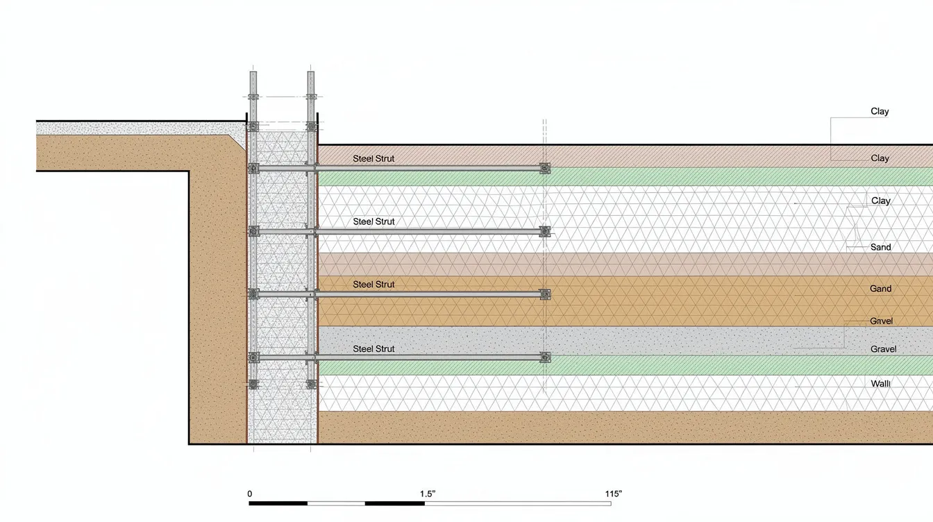
HSs calibration requires determining nine core parameters from laboratory and field test data. The following procedure outlines the parameter determination sequence:
-
Strength parameters (c′, φ′, ψ): Derive effective cohesion and friction angle from consolidated drained or consolidated undrained triaxial tests with pore pressure measurement. For Singapore Upper Marine Clay, published values show c′ = 1.0-5.0 kPa and φ′ = 22-24°. Dilatancy angle ψ is typically set to zero for soft clay.
-
Stiffness parameters (E₅₀ʳᵉᶠ, E_oedʳᵉᶠ, E_urʳᵉᶠ): E₅₀ʳᵉᶠ comes from the secant modulus at 50% failure stress in drained triaxial tests. E_oedʳᵉᶠ derives from one-dimensional oedometer consolidation tests. E_urʳᵉᶠ requires unloading-reloading cycles during triaxial or oedometer testing. For Upper Marine Clay: E₅₀ʳᵉᶠ ≈ 2.5-5.2 MPa, E_urʳᵉᶠ ≈ 7.5-15.6 MPa, with power exponent m ≈ 0.8-1.0 and K₀nc ≈ 0.60.
-
Small-strain parameters (G₀ʳᵉᶠ, γ₀.₇): The reference initial shear modulus G₀ʳᵉᶠ is best determined from resonant column tests, bender element tests, or seismic wave velocity measurements. The threshold shear strain γ₀.₇ defines where stiffness degrades to 70% of G₀. When laboratory small-strain test data is unavailable (common in Singapore SI reports), a conservative default of γ₀.₇ = 0.0001 is used based on published correlations for soft clay.
-
Quality control checks: Compare predicted stress-strain curves against laboratory test data. Verify that G₀/E_ur ratios fall within expected ranges for the soil type. Back-analyze deformation data from comparable Singapore basement excavation projects where monitoring data exists. Calibration for problematic clays such as London Clay needs extra attention to swelling, heave, and ground movement when interpreting excavation response.
Sensitivity analyses should vary key parameters to assess their influence on design, and under Eurocode 7, the Limit State Design approach provides a comprehensive method for handling geotechnical uncertainty through parameter selection, partial factors, and sensitivity checks. BCA’s Design Considerations form requires documentation of all laboratory and in-situ test data, correlations used for parameters lacking direct measurements, and the results of sensitivity studies on G₀ʳᵉᶠ and γ₀.₇. Studies comparing HSs to standard Hardening Soil models show that including the small-strain overlay reduces predicted wall deflections by 5-40% compared to classical HS, depending on soil type and excavation geometry.
For Singapore marine clay at Changi, reference calibration data includes: bulk density 14.2-15.7 kN/m³, water content 70-88%, void ratio 1.8-2.2, compression index 0.6-1.5, coefficient of consolidation 0.47-0.6 m²/year, and overconsolidation ratio 1.5-2.5. These properties directly influence consolidation timing in staged excavation models and determine whether undrained or drained conditions govern at each stage.
Drained vs Undrained Analysis Selection
The choice between drained and undrained analysis depends on three factors: soil permeability, loading rate relative to drainage time, and the construction stage being modeled. Model pore-water pressure changes with transient or fully coupled flow-deformation analysis when partial drainage occurs.
|
Factor |
Drained Analysis |
Undrained Analysis |
|---|---|---|
|
Soil type |
Old Alluvium, residual soils, granular fill |
Marine clay, soft clay, saturated clays |
|
Permeability |
k > 10⁻⁶ m/s |
k < 10⁻⁸ m/s |
|
Loading rate |
Slow relative to drainage (weeks-months) |
Rapid relative to drainage (days-weeks) |
|
Strength parameters |
Effective stress: c′, φ′ |
Effective or total stress: su or c′, φ′ with excess pore pressure |
|
Governing condition |
Long-term permanent stability |
Short-term excavation stages |
|
Safety factor basis |
Drained strength (lower for NC clays) |
Undrained strength (may be higher short-term) |
Singapore marine clay has permeability on the order of 10⁻⁹ to 10⁻¹⁰ m/s. Excavation stages typically last days to weeks, meaning undrained conditions dominate during active construction. For permanent ERSS, long-term drained conditions govern stability because excess pore pressures dissipate over months to years, and drained shear strength in normally consolidated marine clay is lower than undrained strength.
Groundwater behavior must be considered during the design of earth retention systems. BCA’s Design Considerations form requires the QP(D) and AC to confirm that effects from both drained and undrained conditions are evaluated, including the influence of time on drainage conditions. The practical approach is to model each excavation stage as undrained for marine clay layers, then run a consolidation analysis to the next stage. These analysis choices also affect embodied carbon, because support type and material selection influence the project’s carbon footprint. Final permanent condition models use drained parameters with steady-state groundwater levels. Basal heave can lead to catastrophic wall collapse in soft clays, and undrained analysis with proper water pressure modeling is essential to check this failure mode.
Common FEA Pitfalls Flagged by Accredited Checkers
Accredited Checkers reviewing BCA structural submissions for temporary works and permanent ERSS return models for revision when they find errors in mesh quality, boundary conditions, construction staging, or result validation. The following issues appear repeatedly in AC review comments.
Mesh Quality and Convergence Issues
Coarse mesh near retaining wall bases, strut connection points, and soil-structure interfaces causes discretization errors that underestimate bending moments and produce unreliable displacement predictions. Mesh refinement is crucial around walls and interfaces for accuracy in simulations.
The fix is straightforward: use fine mesh zones (element size ≤ 0.5 m) within 1-2 wall thicknesses of the retaining wall, around strut/anchor connection nodes, and at the excavation base where basal heave develops. Transition to medium mesh (1-2 m elements) in the zone extending to 1× excavation depth from the wall, then coarse mesh beyond. Run a mesh convergence check by halving element size in the critical zone; if wall deflection changes by less than 5%, the mesh is adequate. Document the mesh layout, element count, and convergence check results in the submission package.
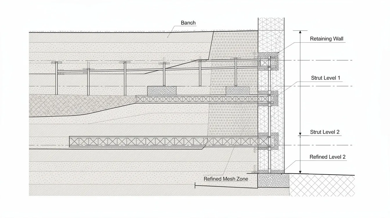
Ill-conditioned elements with aspect ratios exceeding 5:1 or interior angles below 15° cause convergence failures. PLAXIS flags these during mesh generation; address them before running the analysis rather than accepting warnings.
Boundary Condition Errors
Three boundary condition errors account for most AC rejections:
Model boundaries placed too close to the excavation. Lateral boundaries closer than 3× excavation depth and bottom boundaries closer than 2× excavation depth below formation level artificially constrain soil displacement, making the model appear stiffer than reality. This produces non-conservative (low) wall deflection predictions and misleading ground settlement profiles. The AC will compare boundary distances to the excavation geometry and request model extension if boundaries affect results.
Incorrect soil-structure interface properties. Fully bonded interfaces between diaphragm walls and soil overestimate wall friction and underestimate relative displacement. For concrete walls against marine clay, interface strength reduction factors (R_inter) of 0.5-0.67 are typical. For sheet piles in sand, R_inter of 0.67 applies. Soil-structure interaction affects wall deflection and soil pressure, and incorrect interface modeling distorts both.
Groundwater modeling errors. Common mistakes include fixing a single water table level without modeling seepage around the wall toe, ignoring artesian pressure in deeper aquifers, and neglecting the difference between hydrostatic and steady-state seepage pore pressure distributions. PLAXIS 2D simulates groundwater flow and pore pressure distribution, but only when the user defines proper groundwater boundary conditions. Diaphragm walls are preferred for deep, water-bearing excavations precisely because they function as groundwater cutoffs; the model must reflect this by assigning appropriate permeability to the wall elements and defining flow boundaries on both sides.
Construction Sequence Modeling
Sequential staging must mirror the physical construction timeline for accurate modeling. AC reviewers flag models where:
-
All excavation occurs in a single phase rather than matching the actual lift-by-lift sequence
-
Steel struts or ground anchors are activated simultaneously rather than at the correct excavation depth
-
Strut preloads are omitted, producing unrealistically high initial wall movement
-
Temporary-to-permanent excavation support transitions (strut removal, permanent slab casting) are not modeled as separate stages
-
Time between stages is zero in undrained analyses, ignoring consolidation and pore pressure changes
The construction sequence in the model must match the project’s method statement and intended load paths. For a typical braced excavation with diaphragm wall construction, this means: initial geostatic stress generation, wall installation (wished-in-place or modeled), first excavation lift, first level strut installation with preload, second excavation lift, and so on until formation level. Each stage requires appropriate drainage conditions (undrained for clay layers during rapid excavation, drained for granular soils), and consolidation phases between stages where partial drainage affects pore pressures.
BCA requires that accidental failure scenarios (loss of one strut) be modeled as separate load cases. The Design Considerations form asks for effects of varying loads during construction and effects of support removal.
Results Interpretation and Validation
Accepting FEM outputs without cross-checking against independent methods is the most common cause of AC rejection on technical grounds. Accredited Checkers expect:
-
Wall bending moments and strut forces compared against Rankine or Coulomb earth pressure calculations. Differences greater than 30% require explanation.
-
Maximum wall deflection compared against empirical charts (e.g., Clough & O’Rourke) for the soil type and excavation depth. Temporary ERSS must limit ground deformation to millimeters; if FEM predicts larger movements, the design needs revision or the prediction needs justification.
-
Ground settlement profiles compared against published settlement trough correlations for similar Singapore projects.
-
Sensitivity analysis results showing how ±20% variation in G₀ʳᵉᶠ and γ₀.₇ affects wall deflection and strut forces.
Result checks should also confirm realistic load paths through the support system as the construction sequence changes.
These habits matter more in modern construction, allowing engineers to defend serviceability predictions during review.
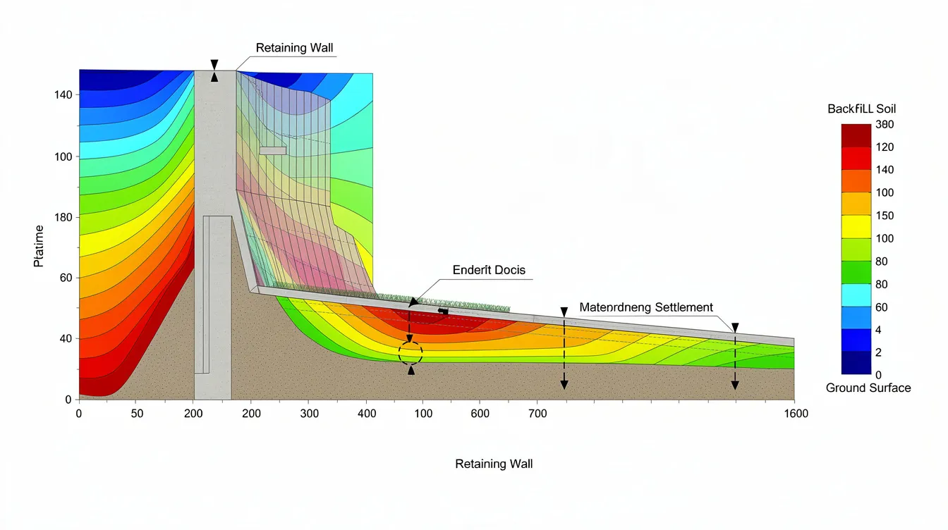
BCA requires specific risk assessments for sheet pile declutching, a failure mode that cannot be captured in standard FEM but must be addressed separately, and regulatory bodies expect those checks to be documented for submission review. For soldier pile systems, simplified wall assumptions can mislead results in flowing sands where ground loss may develop between lagging elements. Contiguous bored piles are also discontinuous systems with a small gap between piles, so equivalent stiffness assumptions must be justified. Secant or diaphragm wall arrangements may be preferred where the retained ground or support system must behave as extremely stiff. Use advanced soil models like Hardening Soil to predict ground movement and settlement, but always verify the predictions are physically reasonable before submission because that validation supports structural design decisions for permanent and temporary excavation support systems. When basal heave is controlled using jet grouting, the base improvement should be reflected in the model. In one reviewed interpretation, the project utilized top-down sequencing and monitoring records to validate predicted movements.
Conclusion and Next Steps
Producing FEM analyses that pass BCA and Accredited Checker review requires three capabilities: correct HSs model calibration using Singapore soil data, appropriate analysis type selection for each construction stage, and documentation that directly addresses the BCA Design Considerations for ERSS checklist.
The HSs model with small-strain stiffness overlay produces more realistic wall deflection predictions than standard Hardening Soil (5-40% lower deflections depending on soil type and geometry), but only when G₀ʳᵉᶠ and γ₀.₇ are calibrated against actual test data or justified conservative defaults. Choosing between PLAXIS 2D and 3D depends on geometry regularity, presence of corner effects, and the BCA submission category. Drained and undrained analyses must both appear in the submission, with undrained conditions governing short-term excavation stages in marine clay and drained conditions governing long-term permanent stability.
To implement these practices on your next project:
-
Review your SI report for small-strain test data (resonant column, bender element). If absent, document the empirical correlations and conservative defaults (γ₀.₇ = 0.0001) you will use, and include sensitivity analyses on these values.
-
Run mesh convergence checks on every model and document the results. Verify boundary distances exceed 3× excavation depth laterally and 2× below formation.
-
Model the full construction sequence stage-by-stage, including strut preloads, temporary support removal, and consolidation phases between stages.
-
Cross-check wall forces and deflections against hand calculations and empirical methods before submitting to the Accredited Checker.
-
Complete BCA’s Design Considerations for ERSS form with specific references to model output locations, sensitivity study results, and monitoring plan trigger levels tied to AAA alarm values.
Related topics that affect ERSS modeling quality include advanced in-situ testing programs for small-strain stiffness measurement, structural modelling and design analysis for load transfer to permanent structures, and PE endorsement requirements for certifying FEM-based designs in Singapore.
Additional Resources
-
BCA Structural Plan Application Guidelines for ERSS submission requirements and SI report standards
-
BCA ERSS Submission Requirements (March 2024) for excavation depth thresholds and QP/AC involvement criteria
-
BCA Design Considerations for ERSS Form for the mandatory checklist covering soil parameters, drainage conditions, and sensitivity analyses
-
AMAN Engineering’s finite element and numerical analysis services for PLAXIS modeling support on complex ERSS projects
-
Guide to BCA Submission for Temporary Works for temporary ERSS submission procedures