
Key Takeaways
A sound I&M plan connects ERSS design assumptions with measurable site behaviour and clear decisions. It should be prepared as a working safety document, not merely as an attachment to an approval submission.
- Define the plan’s purpose, scope, responsibilities, and approval pathway before construction.
- Base monitoring locations and instrument types on ground conditions, excavation geometry, and nearby sensitivities.
- Establish reliable baseline readings, data checks, and documented trigger levels.
- Set out who reads, reviews, reports, and responds to changing site conditions.
- Keep the plan aligned with ERSS staging, design changes, authority submissions, and final records.
Establish the purpose and approval requirements of the I&M plan
An Instrumentation and Monitoring plan for an ERSS project should explain how observations will support safe design verification and construction decisions. It needs to translate the geotechnical assessment into a practical system of instruments, readings, thresholds, and responses. The plan should also identify the documents and professional inputs needed for BCA review. When prepared early, it gives the project team a shared reference before excavation begins.
Define how the plan supports ERSS design and construction safety
The plan should describe the behaviour that must be observed as excavation proceeds, including retaining system movement, ground settlement, groundwater response, and effects on adjacent assets. These observations allow the project team to compare actual performance with the assumptions used for the ERSS design. The document should state how readings will be reviewed at each construction stage and how unusual trends will be investigated. Its central purpose is to provide timely information for safe work sequencing, not simply to produce a set of numbers.
Identify BCA submission expectations and project-specific conditions
BCA submissions should be assembled around the project’s actual risks, design documents, and temporary works arrangements. The I&M plan commonly needs instrument layouts, technical specifications, trigger criteria, reading schedules, reporting arrangements, and response procedures, together with relevant calculations and drawings. Requirements may also be affected by excavation depth, adjacent infrastructure, groundwater conditions, and authority requirements. Aman Engineering Consultancy’s documented services include BCA submission preparation and response to authority comments, which can support the coordination of these technical materials.
Clarify the responsibilities of QPs, contractors, and monitoring specialists
A plan is effective only when responsibility is assigned at every step. The QP should oversee the engineering interpretation and confirm that monitoring remains consistent with the approved design, while the contractor should protect instruments, provide access, and follow the agreed response procedures. Monitoring specialists collect or process readings, check data quality, and bring significant changes to the designated engineer’s attention. The plan should name deputies, communication routes, and decision-making authority for periods when key personnel are unavailable.
Align the plan with the design assumptions, construction sequence, and risk assessment
Monitoring must follow the logic of the ERSS design. A plan prepared without reference to strut levels, anchor installation, excavation lifts, dewatering stages, or predicted deformation may collect useful data too late to guide the work. Cross-reference each monitoring activity to the relevant design assumption and risk assessment item. This alignment also makes later revisions easier because the team can identify which instruments and trigger values are affected by a design or method change.
Assess site conditions and identify monitoring risks
Site assessment provides the basis for deciding what to monitor and where to monitor it. The review should combine investigation records, design information, site observations, and the condition of surrounding properties. It should not treat the excavation boundary as the only area of concern, since ground movement and groundwater effects can extend beyond the site. A clear risk picture helps the team spend monitoring effort where it can influence decisions.
Review ground investigation data, soil parameters, and groundwater conditions
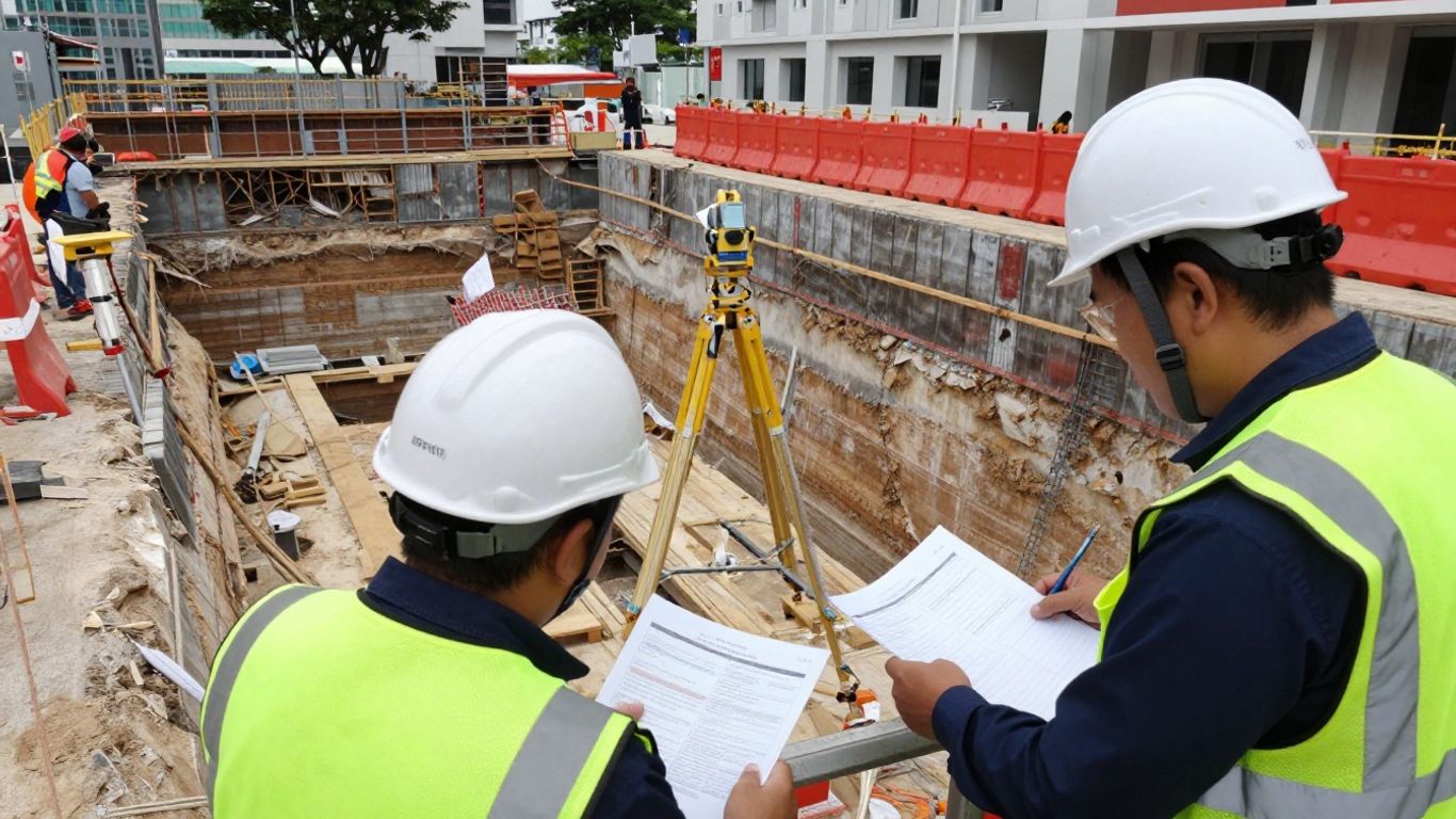
Begin with borehole logs, laboratory results, groundwater observations, previous site records, and the parameters adopted for analysis. Note changes in soil layers, soft or compressible deposits, fill, weathered rock, permeable strata, and possible water-bearing horizons. The plan should identify uncertainty rather than conceal it, especially where investigation coverage is limited. Groundwater levels and seasonal variation should be considered when selecting instruments and establishing the baseline period.
Map nearby buildings, roads, utilities, and other sensitive structures
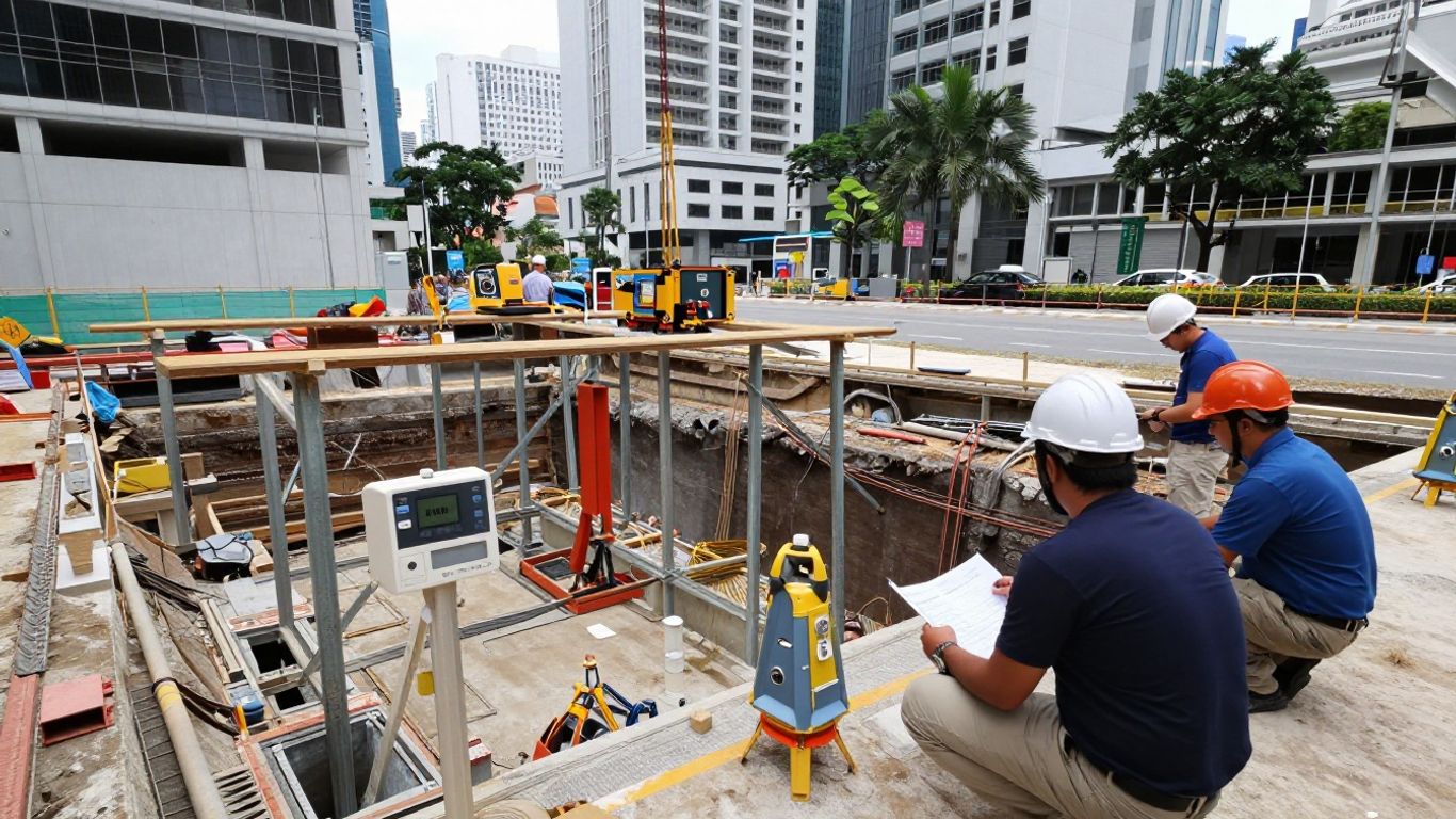
Prepare a coordinated plan showing the excavation, retaining system, monitoring points, neighbouring structures, roads, services, drainage routes, and other sensitive receptors. Where records are incomplete, confirm locations through surveys, utility information, and targeted site checks. Existing building form, foundation type, age, and visible defects can affect the significance of later movement. A nearby Singapore geotechnical practice illustrates the broader professional context in which geotechnical study, statutory submission, construction supervision, and analysis are coordinated.
Evaluate risks from excavation, lateral movement, settlement, and groundwater drawdown
Risk evaluation should distinguish between the likely mechanism and the consequence if that mechanism develops. Deepening excavation can alter stress conditions, retaining wall deflection can transmit movement into neighbouring ground, and groundwater drawdown can contribute to settlement in susceptible soils. Consider construction plant, temporary loading, leakage, strut changes, and local obstructions as well as the principal design case. The resulting risk register should identify the instruments, observations, and response actions associated with each material risk.
Set baseline conditions through pre-construction surveys and condition assessments
Baseline work should be completed before construction changes the site. Survey readings, groundwater levels, building condition records, utility inspections, and crack surveys should be dated, referenced, and tied to stable control points. Photographs and written descriptions are particularly useful where later movement could be disputed or difficult to separate from pre-existing defects. A practical instrumentation engineering role reflects the need for data processing, field coordination, and scheduling alongside technical knowledge.
Select instrumentation for ERSS performance monitoring
Instrument selection should follow the engineering question rather than the availability of equipment. Each device has a measurement range, accuracy, installation requirement, and vulnerability to site conditions. The plan should explain what response is being measured, how often it will be read, and how the result will be checked against other observations. A combination of automated and manual methods is often useful where continuity and independent verification both matter.
Match instruments to the movement or response being measured
Start with a measurement matrix linking each risk to an instrument and an interpretation method. Retaining wall displacement, ground settlement, groundwater pressure, structural cracking, and utility movement require different observation approaches. Include expected magnitude, direction, rate, and duration of change where these are relevant to the risk. The specification should also state the limitations of each instrument so that a single reading is not treated as a complete description of site behaviour.
Use inclinometers to track retaining wall deflection and lateral ground movement
Inclinometers installed in or near retaining elements can provide a profile of lateral movement with depth. The plan should record casing alignment, datum, measurement intervals, access arrangements, and the method for identifying a change from the baseline profile. Readings are more informative when compared across excavation stages and with surface survey points. Protect the casing from plant and construction damage, and define how a blocked or distorted casing will be assessed.
Monitor settlement with precise levelling points, settlement markers, and survey prisms
Settlement monitoring should cover the ground and the assets that could be affected by it. Precise levelling points and settlement markers provide repeatable vertical measurements, while survey prisms can support more frequent or remote observations where line of sight is available. The plan should define stable benchmarks, survey closures, observation geometry, and tolerances for rejecting a reading. Interpretation should consider both absolute movement and differential movement between nearby points.
Measure groundwater response with standpipes and vibrating-wire piezometers
Standpipes and vibrating-wire piezometers serve different monitoring needs and should be located at depths relevant to the assessed groundwater regime. Standpipes can provide direct water-level observations, while vibrating-wire piezometers can support readings where pressure response and remote collection are required. Installation records should include filter depth, grout details, response checks, and the time allowed for equilibration. Readings should be considered alongside pumping, rainfall, seepage, and excavation activities rather than viewed in isolation.
Include building, utility, and structural crack monitoring where appropriate
Sensitive buildings may require crack gauges, tell-tales, precise survey points, tilt observations, or other condition-specific measures. Utility monitoring should reflect the service type, material, alignment, and consequence of movement, with access and operator requirements agreed in advance. Roads and pavements may need level and visual surveys at locations where differential settlement is plausible. The selected system should be proportionate to the consequence of movement and supported by a clear inspection record.
Develop monitoring locations, installation details, and data quality controls
A monitoring plan becomes usable when its drawings and procedures are detailed enough for installation crews and reviewers to follow without guesswork. Locations should be coordinated with the ERSS geometry, construction access, temporary works, and the protection of existing services. Quality controls must cover the complete data chain, from installation and baseline readings to reporting and archival. Good documentation also makes it possible to distinguish genuine ground response from an instrument or process error.
Prepare an instrument layout that reflects excavation geometry and risk zones
The layout should show instrument IDs, coordinates, elevations, sections, monitoring zones, and the relationship to retaining elements and sensitive receptors. Concentrate coverage near corners, changes in stiffness, deep excavation zones, water control features, and neighbouring assets where the risk assessment requires closer observation. Include reference points outside the expected zone of influence, subject to their stability being demonstrated. The drawing should be reviewed against the latest construction plan before every significant stage.
Specify installation methods, protective measures, and instrument identification
Each instrument schedule should state the installation method, depth, orientation, materials, protection, access arrangement, and identification code. Labels need to remain legible after hoarding, temporary works, and site traffic change around them. Physical protection should not prevent readings or create a hazard for workers. Photographs, coordinates, installation dates, and installer details should be captured immediately so that the as-built record reflects what was actually installed.
Establish baseline readings, calibration requirements, and verification procedures
Baseline readings should be taken after installation and after the instrument has stabilised sufficiently for its purpose. The plan should state calibration requirements, zero checks, survey closures, repeat readings, and the circumstances requiring an independent verification. Data should be reviewed for drift, spikes, missing values, implausible rates, and inconsistencies between related instruments. This is where early data validation protects the project from responding to a faulty reading as though it were a ground movement event.
Plan for instrument damage, access limitations, interference, and replacement
Instruments can be struck by equipment, covered by construction, affected by vibration, or rendered inaccessible by temporary works. The plan should identify vulnerable locations and provide protection, alternative access, spare equipment, and a replacement process. If an instrument is lost, the team should assess whether nearby readings can maintain sufficient coverage or whether a new location is needed. Any interruption must be recorded with its likely effect on interpretation.
Define data formats, record keeping, and as-built documentation
Use consistent naming, units, timestamps, coordinate references, and file formats across manual and automated readings. Keep raw observations, processed results, validation notes, photographs, calibration records, inspection forms, and reports together under controlled revision. The final as-built package should show installed locations rather than only the proposed layout. A clear record supports trend review, authority queries, handover, and investigation of decisions made during construction.
Set alert, action, and alarm levels
Trigger levels should turn monitoring information into predefined decisions. They are not arbitrary numbers and should not be copied from another site without checking the design, asset sensitivity, and instrument characteristics. The plan should explain what happens when a threshold is approached, crossed, or accompanied by an accelerating trend. Every level must be understandable to the people who collect readings and the engineers who decide on the response.
Establish trigger levels from design predictions and allowable movements
Use design predictions, allowable movements, structural tolerance, ground conditions, and the condition of nearby assets to develop initial trigger values. Consider displacement, settlement, tilt, crack width, groundwater level or pressure, and rate of change where applicable. Predictions should be treated as an engineering basis rather than a guarantee of actual behaviour. The final values should be reviewed by the responsible QP and recorded with the assumptions behind them.
Differentiate alert, action, and alarm responses for each monitoring parameter
An alert level may require closer observation and confirmation, while an action level may require engineering review, a construction hold, or mitigation. An alarm level should identify the urgent measures needed to protect people, structures, and the works. The response should be parameter-specific: a groundwater change may prompt pumping review, while wall movement may require checking struts or excavation sequence. Avoid vague instructions such as “monitor closely” without naming the person, timeframe, and decision required.
Consider observational data, construction stages, and instrument uncertainty
Trigger interpretation should account for the stage of excavation and the expected response after a particular operation. Instrument precision, repeatability, survey conditions, temperature effects, and data processing can all affect apparent movement. A single exceedance may require confirmation, but a rapid trend or correlated change across several instruments may justify immediate action. The plan should state how engineering judgement is applied without allowing uncertainty to become an excuse for inaction.
Set criteria for adjacent structures, utilities, roads, and groundwater levels
Different receptors need different criteria because their tolerances and failure consequences are not the same. A heritage or brittle structure may need tighter movement or crack limits than a flexible pavement, while a utility may be governed by alignment, joint performance, or service continuity. Groundwater criteria should reflect drawdown, pore-pressure response, seepage, and the potential for settlement. Include visual inspection findings and complaints within the response framework rather than relying solely on numerical instruments.
Document the engineering basis for every trigger value
For each threshold, record the parameter, unit, location, source of value, design assumption, uncertainty, responsible reviewer, and response. Explain whether the value is linked to predicted movement, an allowable limit, an asset assessment, or a construction control requirement. When a value changes, preserve the original record and note the approving professional and effective date. This traceability is essential during BCA review and when the team must explain why a particular action was taken.
Implement monitoring, reporting, and response procedures
The implementation section should turn the plan into a daily site process. It should define when readings are taken, who checks them, how results are communicated, and what happens when information is incomplete or concerning. Monitoring is most useful when it is connected to the construction programme and reviewed before the next irreversible activity. The project should also allow for both routine reporting and immediate escalation.
Define reading frequency before, during, and after each excavation stage
Reading frequency should increase around activities that can change ground response, such as excavation, strutting, anchoring, pumping, and removal of temporary support. The schedule should cover pre-stage readings, readings during the work, post-stage observations, and a period of continued monitoring after the stage is complete. Automated collection may support frequent measurement, but it does not remove the need for visual checks and independent review. Adjustments to frequency should be documented with their engineering rationale.
Assign Geotechnical Instrumentation Engineers to data collection and interpretation
Geotechnical Instrumentation Engineers should have clearly defined duties for collection, processing, trend interpretation, and reporting. They should understand the installation records, design assumptions, trigger levels, and construction sequence rather than reviewing graphs without context. Aman Engineering Consultancy’s documented geotechnical RTO services include instrumentation monitoring and data interpretation, as well as excavation and earth retaining structures supervision. The appointment should also state how the specialist communicates with the QP and site management.
Create workflows for automated alerts, manual readings, and data validation
Automated alerts should identify the instrument, threshold, timestamp, and current value, then route the notification to named recipients. Manual readings should use controlled forms and independent checks where practical. Before an alert is escalated, the workflow should test for instrument faults, transcription errors, unstable survey control, and confirmation from related points. A validated result can then be interpreted in relation to the construction activity that may have caused it.
Establish reporting schedules for the QP, project team, and relevant authorities
Routine reports should state the monitoring period, instruments read, missing data, trends, trigger status, construction activities, photographs, and recommended follow-up. Set different reporting intervals for daily site communication, weekly engineering review, stage completion, and exceptional events. Reports to the QP and project team should be timely enough to influence the next work sequence. Where authority reporting or inspection coordination is required, responsibilities and submission records should be retained.
Specify escalation, mitigation, and emergency response actions
The response procedure should begin with confirmation and notification, then move to engineering assessment and control of the relevant work. Possible measures may include stopping or restricting excavation, checking or strengthening temporary support, modifying dewatering, installing additional monitoring, backfilling, or protecting an affected asset. Emergency contacts, site access, safe isolation, and authority communication should be listed in the plan. Aman Engineering Consultancy also documents authority inspections coordination, including facilitating and attending inspections by BCA and other relevant authorities to support necessary clearances.
Integrate the I&M plan into ERSS construction and BCA approval
The I&M plan should remain active from design review through construction and close-out. It must be coordinated with temporary works drawings, method statements, inspection points, permits, and the programme so that monitoring is available before the risk arises. Approval documents should match the field installation and the current design revision. Treating the plan as a living engineering control makes it more useful to the QP, contractor, monitoring team, and authority reviewers.
Link monitoring requirements to excavation, strutting, anchoring, and dewatering stages
Create a stage matrix showing which instruments must be installed, read, and reviewed before each activity begins. For excavation, link observations to lift depth and exposed wall height; for strutting or anchoring, relate readings to installation, stressing, and load-transfer events. Dewatering stages should identify groundwater and settlement observations that must be checked before pumping changes. Hold points should be included where the next activity depends on acceptable monitoring results.
Coordinate instrumentation with temporary works, site access, and construction logistics
Instrument locations must remain accessible without compromising workers, plant movement, lifting operations, or temporary support. Coordinate protective details with the contractor and confirm that access remains possible after each change to hoarding, ramps, decks, or strutting. Cable routes, power supplies, telemetry equipment, and survey lines may require their own logistics plan. A pre-start coordination review can identify conflicts before installation becomes difficult or unsafe.
Prepare the technical documents, drawings, calculations, and monitoring records for submission
The submission package should be internally consistent. Include the I&M narrative, instrument schedule, layout drawings, sections, installation details, baseline records when available, trigger calculations, response matrix, and relevant ERSS design information. Check that revision numbers, coordinates, terminology, and responsibility assignments agree across every document. Aman Engineering Consultancy’s documented scope includes detailed analysis and design optimization, production of construction drawings, BCA submission preparation, response to authority comments, and final documentation and approval.
Manage design changes, unexpected readings, and revised mitigation measures
Changes to wall type, excavation depth, strut arrangement, anchor sequence, groundwater control, or neighbouring conditions should trigger a review of the I&M plan. Unexpected readings require a structured investigation that considers instrument reliability, local site activity, correlated measurements, and the possibility that the design model needs revision. Record temporary controls, engineering advice, approvals, and revised thresholds rather than replacing the old plan without an audit trail. The QP should confirm when the revised arrangement is suitable for continued work.
Close out the plan with final readings, trend assessment, and as-built records
Close-out should occur only after the relevant construction stages are complete and the agreed post-construction monitoring period has been satisfied. Review final trends, residual movement, groundwater recovery, outstanding defects, instrument condition, and any unresolved risks. Archive the final readings, reports, photographs, calibration information, response records, and as-built drawings in a controlled package. A concise close-out statement should explain whether observed behaviour remained within the engineering basis and identify any continuing inspection needs.
Conclusion
A BCA-ready I&M plan is a coordinated engineering document that connects ERSS assumptions, site evidence, instrumentation, trigger levels, construction stages, and professional responsibilities. When Geotechnical Instrumentation Engineers, QPs, contractors, and authority-facing consultants work from the same current information, monitoring becomes a practical decision system for managing excavation risk rather than a record produced after the fact.
Frequently Asked Questions
What is the purpose of an I&M plan for ERSS works?
It defines how ground, retaining systems, groundwater, and nearby assets will be observed during construction, and how the project team will respond when readings or site conditions indicate increased risk.
When should an I&M plan be prepared?
It should be developed during ERSS design and reviewed before construction begins. Instrument installation, baseline readings, and access arrangements must be planned early enough to support the first excavation stage.
Who is responsible for reviewing monitoring data?
The plan should nominate the QP and suitably competent monitoring specialists, including their deputies and communication routes. The contractor remains responsible for site coordination, instrument protection, and following agreed construction controls.
What instruments are commonly used for ERSS monitoring?
The selection depends on the risk, but may include inclinometers, settlement points, survey prisms, standpipes, vibrating-wire piezometers, crack gauges, and condition survey tools.
How are alert, action, and alarm levels determined?
They are developed from design predictions, allowable movement, receptor sensitivity, construction stages, groundwater conditions, and instrument uncertainty. The engineering basis and required response should be recorded for every threshold.
What should happen after a trigger level is exceeded?
The reading should be checked and communicated promptly, then interpreted with related data and current site activity. Depending on the level and trend, the response may include increased monitoring, engineering review, work restrictions, mitigation, or emergency action.
What records should be retained at project close-out?
Keep final layouts, installation and calibration records, raw and processed readings, reports, trigger events, response decisions, photographs, design revisions, and as-built documentation, together with a final trend and risk assessment.