
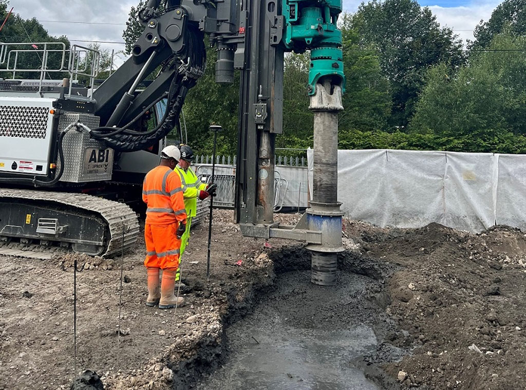
A temporary works engineer is the specialist who designs, analyses, and coordinates temporary structures such as earth retaining systems, scaffolding, strutting, and formwork so a construction project remains safe, stable, and buildable. In Singapore, where dense urban sites, deep excavations, and strict regulatory requirements shape industrial, commercial, and infrastructure projects, that role directly affects structural integrity, site safety, compliance, and programme risk.
For business owners, real estate investors, construction engineers, and companies planning or delivering projects in Singapore, this article explains how temporary works are classified, designed, and integrated with permanent structures. It also outlines key systems used on site, including ERSS, TERS, strutting for excavations, open cut slope methods, scaffold design, and formwork, so readers can better assess technical requirements, project risks, and the expertise needed for complex developments.
Definition and Classification of Temporary Works in Construction Projects
Primary Categories of Temporary Works:
-
Class A – High Risk: Deep excavations exceeding 6m, complex ERSS systems, major falsework supporting significant loads
-
Class B – Medium Risk: Standard excavations 3-6m deep, typical scaffolding systems, standard formwork
-
Class C – Low Risk: Shallow excavations below 3m, basic access scaffolds, simple formwork systems
Structural Engineering Temporary Works
Structural temporary works encompass scaffolding systems, formwork, falsework, propping systems, and temporary bridges or platforms. These systems must be designed to support construction loads, including dead loads, live loads, wind loads, and dynamic construction loads from construction equipment, with load capacities checked to protect site safety. The design process requires structural analysis, calculations, consideration of load combinations, stability analysis, and connection design to ensure safety throughout the construction period. This guidance does not change with project scale; every detail can matter. These systems are vital for enabling safe construction activities during the construction process.
In Singapore’s context, structural temporary works must also account for tropical weather conditions. Temporary structures must be designed to withstand environmental conditions on the construction site, and the design wind speed varies based on the exposure period and importance of the structure. Typhoon conditions, though rare, must be considered for long-term temporary works. Additionally, the high rainfall intensity in Singapore necessitates proper drainage design and consideration of water accumulation on horizontal surfaces so support remains securely in place.
SS EN 1991-1-4:2005 – Eurocode 1: Actions on structures – Wind actions SS EN 1991-1-6:2005 – Eurocode 1: Actions on structures during execution BS 5975:2019 – Code of practice for temporary works procedures and guidance governing structural safety
Integration with Permanent Works
Temporary works support permanent structures during construction, so the interface between temporary and permanent works requires careful coordination and design integration. These systems provide stability, access, and support during different construction phases, helping the project progress safely toward the final structure and the performance expected to last for decades. Temporary works often impose loads on partially completed permanent structures, requiring analysis of the permanent works in their temporary condition. Cast-in items for temporary works support, such as anchors, brackets, and embedments, must be designed considering both temporary and permanent load conditions.
Earth Retaining Stabilising Systems (ERSS)
Earth Retaining Stabilising Systems (ERSS) represent a fundamental category of temporary works essential for deep excavation projects in Singapore’s urban environment, and the temporary works engineer role is central to their planning and delivery. These systems are designed to provide lateral support to vertical or near-vertical excavated soil faces, preventing collapse and controlling ground movements to protect adjacent structures and infrastructure. The selection and design of ERSS depend on various factors including soil conditions, groundwater levels, excavation depth, proximity to existing structures, and construction methodology. The engineer is responsible for ensuring the safety and stability of these temporary structures. Early involvement improves project safety and design coordination.
Singapore’s rapid urban development and limited land area have necessitated increasingly deep excavations for basements, underground transportation systems, and utility tunnels. ERSS designs must address the complex interaction between soil, groundwater, and structures while maintaining strict movement control criteria. The typical allowable ground settlement adjacent to excavations in Singapore ranges from 10mm to 25mm, depending on the sensitivity of nearby structures and utilities.
Common ERSS Types in Singapore:
-
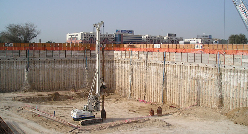
Sheet Pile Walls: Steel or reinforced concrete sheets driven into ground, suitable for excavations up to 15m deep in soft soils
-
Contiguous Bored Pile Walls: Series of bored piles installed with gaps, effective in competent soils above groundwater
-
Secant Pile Walls: Interlocking bored piles providing water-tightness, suitable for deep excavations up to 30m
-
Diaphragm Walls: Reinforced concrete walls constructed in-situ, ideal for very deep excavations exceeding 30m
-
Soil Nail Walls: Reinforced soil mass using passive inclusions, suitable for temporary slopes in competent ground
-
Ground Anchors: Pre-stressed tendons providing active support, used in combination with other wall types
The design of ERSS in Singapore follows the limit state design philosophy as prescribed in SS EN 1997-1 (Eurocode 7). The design process involves verification of Ultimate Limit States (ULS) and Serviceability Limit States (SLS) using partial factors applied to actions and material properties. The design must demonstrate adequate safety against various failure modes including overall stability, structural failure, hydraulic failure, and excessive deformations.
Geotechnical investigation forms the foundation of ERSS design. Singapore’s Building Control Regulations mandate comprehensive site investigation for all deep excavation projects. The investigation typically includes boreholes at 15-30m spacing, in-situ testing (SPT, CPT, pressuremeter tests), laboratory testing for soil parameters, and groundwater monitoring. The geological model developed from these investigations must capture the spatial variability of soil properties and identify potential geohazards.
Sheet Pile Wall Design
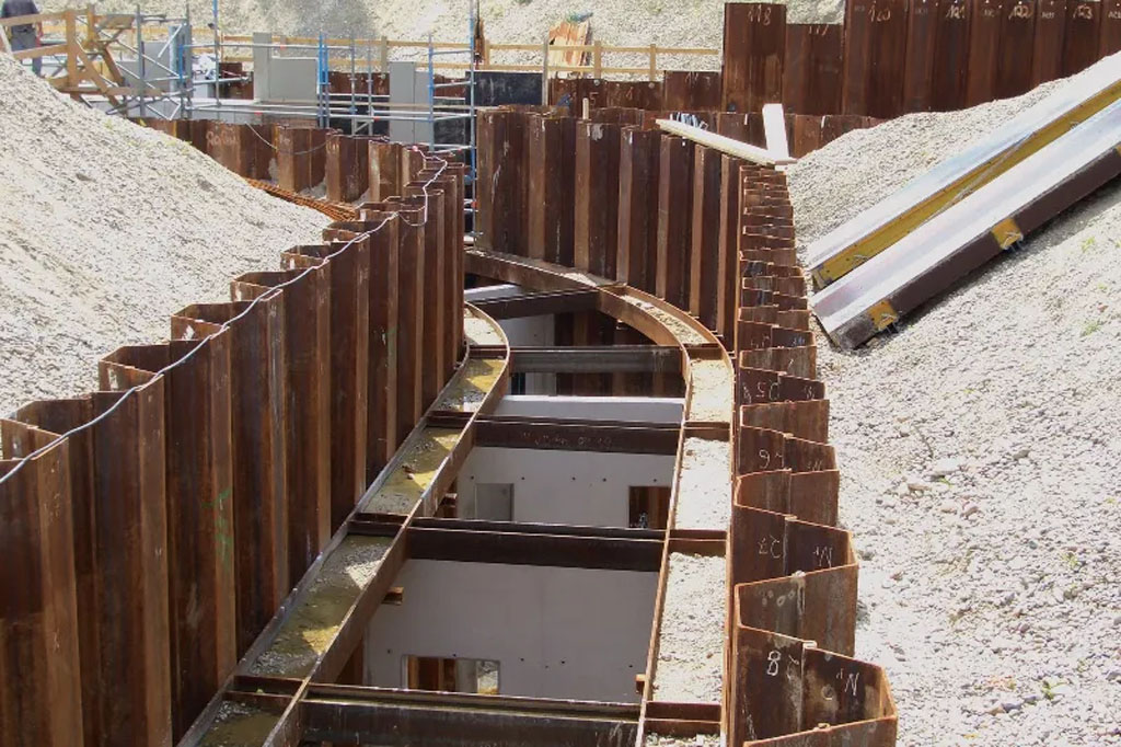
Sheet pile walls are among the most commonly used ERSS in Singapore, particularly for temporary excavations in soft soils and waterfront structures. The design process involves selection of appropriate sheet pile sections, determination of embedment depth, and design of support systems (struts or anchors). Modern sheet pile design in Singapore increasingly uses high-strength steel grades (S355GP to S430GP) to optimize section properties and reduce installation difficulties.
The calculation of embedment depth follows the principles of force and moment equilibrium, considering active and passive earth pressures, surcharge loads, and hydrostatic pressures. The free earth support method and fixed earth support method are commonly employed, with the choice depending on soil conditions and wall flexibility. Singapore’s high groundwater table often necessitates consideration of seepage forces and potential for hydraulic failure.
Bored Pile Wall Systems
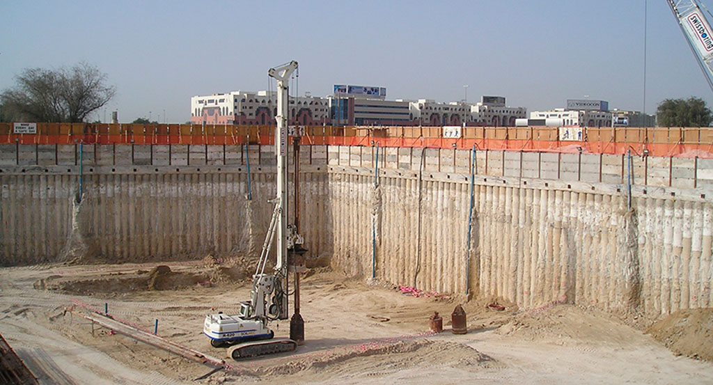
Contiguous bored pile walls consist of a series of reinforced concrete piles installed at close centers with small gaps between piles. The typical pile diameter ranges from 600mm to 1500mm, with center-to-center spacing of 1.1 to 1.3 times the pile diameter. These walls are suitable for excavations above the groundwater table or where limited water ingress is acceptable, subject to site assessments that help engineers understand wall suitability and project constraints. The structural design considers the piles as individual vertical cantilever or propped members, with earth pressure distribution based on soil arching effects between piles and the relevant specifications.
Secant pile walls provide a water-tight barrier through the intersection of adjacent piles. The construction sequence involves installation of primary (soft) piles followed by secondary (hard) piles that cut into the primary piles. The typical overlap ranges from 75mm to 150mm, depending on construction tolerances and water-tightness requirements. The design and construction must also satisfy local building codes and safety regulations. The design must account for the composite action between primary and secondary piles, with particular attention to the integrity of joints under lateral loading.
Diaphragm Wall Construction and Design
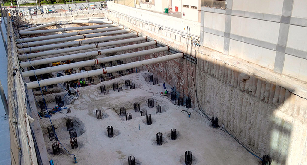
Diaphragm walls represent the premier solution for deep excavations in Singapore, particularly for permanent basement walls and cut-and-cover tunnel construction. These reinforced concrete walls, constructed using the slurry trench technique, can extend to depths exceeding 50m and provide excellent water-tightness and structural capacity. The typical wall thickness ranges from 600mm to 1500mm, with panels typically 2.5m to 6m in length.
The construction process involves excavation under bentonite or polymer slurry support, followed by reinforcement cage installation and concrete placement using tremie pipes. The slurry properties must be carefully controlled to maintain trench stability, with specific requirements for density (1.03-1.10 g/cm³), viscosity (30-50 seconds Marsh cone), and pH (7-11). Singapore’s variable geology often requires adjustment of slurry properties to suit different soil layers. During the construction phase, engineers oversee implementation to ensure slurry control, alignment, and stability, drawing on site experience.
Critical Design Considerations for Diaphragm Walls:
-
Panel joint design and water-stopping details
-
Reinforcement detailing for moment reversal zones
-
Concrete mix design for tremie placement (minimum grade C35/45)
-
Verticality tolerances (typically 1:300 to 1:400)
-
Guide wall design to control alignment and position
-
Temporary works for slurry plant and handling systems
Temporary Earth Retaining Systems (TERS)
Temporary Earth Retaining Systems (TERS) in Singapore encompass a range of engineered solutions designed specifically for short to medium-term earth retention during construction activities. Unlike permanent retaining structures, TERS are optimized for temporary loading conditions, construction efficiency, and reusability where applicable. The selection of appropriate TERS depends on factors including design life (typically 6 months to 2 years), soil conditions, groundwater regime, allowable ground movements, site constraints, and economic considerations, and temporary works engineers collaborate with the project team during construction to develop the appropriate solution. Effective risk management is also essential for safe, efficient design and execution.
Ground Improvement as TERS
Ground improvement techniques serve dual purposes as both temporary earth retention and soil stabilization measures. In Singapore’s soft marine clay and loose sandy soils, methods such as jet grouting, deep soil mixing, and ground freezing provide temporary support while enhancing soil properties. These techniques are particularly valuable when conventional TERS would cause excessive ground movements or where space constraints preclude installation of structural walls.
Jet grouting creates soil-cement columns through high-pressure injection of cementitious grout, forming a gravity retaining structure or cutoff wall. The design requires determination of column diameter (typically 0.8-2.0m), spacing, and overlap to achieve required strength and permeability. Quality control through core sampling and integrity testing is essential, with minimum unconfined compressive strength typically specified as 1-3 MPa for temporary applications.
Hybrid TERS Systems
Complex urban excavations often require hybrid TERS combining multiple retention methods to address varying site conditions. A typical example involves sheet piles in the upper soft soils transitioning to rock anchors in the underlying competent strata. The design of hybrid systems requires careful analysis of load transfer between different components, collaboration during initial design and planning, and consideration of differential stiffness effects on earth pressure distribution. Hybrid systems also require effective communication among stakeholders to coordinate interfaces between components.
The connection details between different TERS components are critical for system integrity. Welded connections must comply with SS EN 1090-2 for structural steel execution, while bolted connections follow SS EN 1993-1-8 design requirements. The fatigue assessment may be necessary for connections subject to cyclic loading from construction equipment or traffic-induced vibrations.
Strutting Systems for Deep Excavations
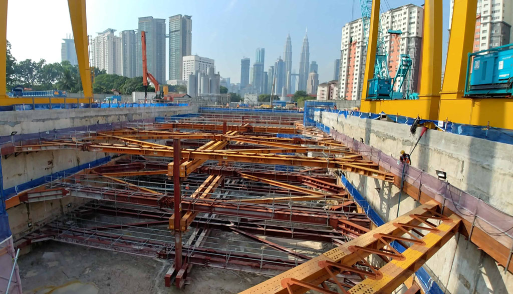
Strutting systems provide critical lateral support for earth retaining structures in deep excavations throughout Singapore. These horizontal or inclined structural members transfer earth pressure loads from retaining walls to opposite walls or to internal support points, enabling excavation to proceed safely to design depths. The selection between strutting and alternative support methods such as ground anchors depends on site geometry, soil conditions, presence of underground utilities, and restrictions on working beyond site boundaries.
Strut Design and Analysis
Strut design begins with determination of design loads based on earth pressure distributions and tributary areas. The apparent earth pressure envelope method, as recommended in various international codes, provides simplified load distributions for preliminary design. However, Singapore’s variable soil conditions often require more sophisticated analysis using beam-on-elastic-foundation or finite element methods to capture soil-structure interaction effects accurately.
Strut Load Calculation:
Pstrut = Ka × γ × H × Sh × Sv × Fs
Where: Ka = Active earth pressure coefficient γ = Soil unit weight H = Depth factor Sh = Horizontal strut spacing Sv = Vertical tributary height Fs = Safety factor (typically 1.3-1.5)
Waling Beam Design
Waling beams distribute strut loads along the retaining wall face, ensuring efficient load transfer and preventing local failure. These continuous horizontal members, typically steel universal beams or built-up sections, must be designed for combined bending and axial effects. The design considers the waling as a continuous beam on multiple supports (struts) with earth pressure loading from the tributary wall area.
Connection design between waling and retaining wall requires particular attention. For sheet pile walls, standard clutch connections or welded brackets transfer loads, while bored pile walls may utilize cast-in plates or through-bolts. The eccentricity between strut centerline and wall face induces additional moments that must be considered in both waling and connection design.
Open Cut Slope Techniques
Slope Stability Fundamentals in Singapore Context
Open cut slope techniques provide an economical alternative to vertical excavation support systems where sufficient land area is available. In Singapore’s construction industry, temporary slopes are commonly employed for infrastructure projects, particularly in areas with lower development density such as industrial zones and transportation corridors. The design of temporary cut slopes must balance safety requirements with economic considerations while addressing Singapore’s challenging geological conditions and intense rainfall patterns. Poorly defined design briefs can lead to errors in temporary slope works, even on smaller civil projects.
Slope stability analysis for open cut excavations employs various methods ranging from simple limit equilibrium to advanced numerical techniques. The method of slices, including Bishop’s simplified method, Spencer’s method, and Morgenstern-Price method, remains the industry standard for routine design. These methods satisfy force and moment equilibrium while considering the internal forces between slices, providing factors of safety against sliding failure.
Slope Geometry and Benching Design
The optimal slope geometry depends on soil properties, groundwater conditions, and available space. In cohesive soils such as Singapore’s Jurong Formation residual soils, slopes of 1V:1.5H to 1V:2H are typical for heights up to 10m. Granular soils and weathered rock may accommodate steeper slopes of 1V:1H to 1V:1.5H, subject to stability verification. The inclusion of intermediate benches at 5-6m vertical intervals improves stability and provides access for maintenance and instrumentation.
Bench design incorporates drainage provisions to prevent surface water accumulation and erosion. Minimum bench width of 3m enables access for maintenance equipment, while 1-2% back-slope gradient ensures positive drainage toward permanent drains. The transition between bench and slope face requires erosion protection through turfing, geotextile placement, or temporary shotcrete application depending on exposure duration and rainfall intensity.
Slope Reinforcement Techniques
Temporary slope reinforcement enhances stability and enables steeper cut angles where space constraints exist. Soil nailing represents the most common reinforcement method in Singapore, involving installation of passive steel or fiber-reinforced polymer bars into pre-drilled holes with cement grout. The typical nail spacing ranges from 1.5 to 2.5m in both directions, with inclination of 10-20 degrees below horizontal to optimize reinforcement effectiveness.
Design of soil nail systems follows the principles outlined in BS 8006-2:2011 and Geoguide 7 (Hong Kong). The analysis considers both internal and external stability, with verification of nail pullout capacity, facing stability, and global stability of the reinforced soil mass. The required nail length typically ranges from 0.6 to 1.0 times the slope height, with longer nails in the upper rows to intersect potential failure surfaces.
Surface Protection and Erosion Control
Surface protection prevents erosion and shallow instability while maintaining overall slope integrity. In Singapore’s high-intensity rainfall environment, surface protection systems must withstand concentrated flows and impact forces from rainfall. Temporary erosion control measures include hydroseeding with fast-germinating grass species, erosion control blankets, or temporary geosynthetic covers.
Shotcrete facing provides robust surface protection for extended exposure periods or where vegetation establishment is challenging. The typical thickness ranges from 75-150mm for temporary applications, with welded wire mesh reinforcement (BRC A6 to A8) providing crack control and local stability. Weep holes at 2-3m spacing ensure drainage behind the facing, preventing hydrostatic pressure buildup that could compromise facing stability.
Scaffold Design and Engineering
Scaffolding systems form an integral component of Singapore’s construction industry, providing temporary access, working platforms, and support structures for various construction activities. The design and implementation of scaffolding must comply with stringent safety regulations while accommodating the unique challenges of high-rise construction, confined urban sites, and tropical weather conditions. Singapore’s Workplace Safety and Health (WSH) Regulations mandate comprehensive design, inspection, and certification requirements for all scaffolding installations.
Scaffold design in Singapore must comply with multiple standards and regulations, primarily SS 280:2018 (Code of Practice for Scaffold) and SS EN 12811 (Temporary Works Equipment – Scaffolds). These standards establish requirements for materials, design methodology, erection procedures, inspection protocols, and dismantling processes. Additionally, the WSH (Scaffolds) Regulations 2011 provides legal requirements for scaffold safety, including certification of scaffold erectors and supervisors.
Key Design Standards for Scaffolding:
SS 280:2018 – Code of Practice for Scaffolds SS EN 12811-1:2003 – Temporary works equipment – Scaffolds – Performance requirements SS EN 12810-1:2003 – Facade scaffolds made of prefabricated components SS EN 39:2001 – Steel tubes for scaffolding BS 5973:1993 – Code of practice for access and working scaffolds (reference document)
Structural Design Methodology
The structural design of scaffolding follows limit state principles, verifying both Ultimate Limit State (ULS) and Serviceability Limit State (SLS) criteria. Design loads include self-weight, imposed loads from workers and materials, wind loads, and special loads such as concrete placement or equipment installation. The load combinations consider various construction scenarios, with appropriate load factors applied according to SS EN 12811-1.
Wind loading represents a critical design consideration in Singapore, particularly for high-rise scaffolding and scaffolds with sheeting or containment screens. The design wind speed varies with height and exposure, following SS EN 1991-1-4 with Singapore National Annex parameters. For scaffolds with design working life exceeding 6 months, the 10-year return period wind speed applies, while shorter-duration installations may use reduced wind speeds with appropriate risk assessment.
Foundation Design for Scaffolds
Tie Systems and Scaffold Stability
Temporary Works Design: Formwork for Buildings and Infrastructure
Formwork systems represent a critical temporary works element in concrete construction, providing the mold that shapes concrete members while supporting loads during placement and curing.
Modern formwork design integrates structural engineering principles with construction methodology, considering not only load capacity but also constructability, safety, and concrete finish quality for contractors and clients. The tropical climate influences formwork design through considerations for rainfall during concrete placement, thermal effects on formwork materials, and accelerated concrete strength development. Singapore’s high-rise construction sector has driven innovations in climbing formwork, jump forms, and slip-form systems that enable efficient construction of vertical elements.
Formwork design follows limit state principles as outlined in SS EN 1992 (Eurocode 2) and BS 5975:2019. The design process verifies structural adequacy under various load combinations while ensuring serviceability requirements for deflection control and concrete finish quality; changes to formwork design, sequence, or loading should be documented with traceable records for accountability. Load considerations include concrete self-weight, construction live loads, impact from concrete placement, wind loads on vertical formwork, and lateral pressure from fresh concrete. Regular inspections verify formwork stability before and during concrete placement. Design proficiency also supports smoother team coordination and overall project success.
Lateral Pressure of Fresh Concrete (SS EN 1992):
Pmax = MIN[γc × h ; 5√(v) + 20] Where: γc = Unit weight of concrete (typically 25 kN/m³) h = Height of fresh concrete v = Rate of placement (m/hr)
Engineers may join site and design reviews as required; for project-specific advice, contact the team.