
Introduction
Near surface mounted (NSM) CFRP bars provide a practical, minimally invasive route to boost both negative and positive bending moment capacities of existing concrete decks across Singapore and ASEAN. By embedding carbon fiber reinforced polymer rods into shallow, epoxy-filled grooves cut into the concrete cover, engineers use the broader near surface mounted FRP system to upgrade ageing slabs, bridge decks, carpark structures, and transfer plates without demolition, without increasing slab depth, and often without taking the structure out of service.
This article is written for asset owners, developers, contractors, and consulting engineers who need to understand how NSM CFRP flexural strengthening works in practice within a civil engineering context-from concept and design intent through step-by-step installation in saw-cut grooves, to inspection, durability, and authority submission considerations in Singapore. It does not reproduce full design equations or replace a Professional Engineer’s calculations; instead it provides the technical depth required to plan, propose, and supervise NSM retrofits confidently.
How do NSM CFRP bars improve flexural capacity? As a fiber reinforced polymer CFRP solution for flexural upgrades, CFRP bars can significantly increase flexural capacity, often by 30 % to over 100 %, by providing additional tensile reinforcement in regions where existing steel bars are insufficient-on the soffit for sagging zones or on the top surface for hogging zones-thereby raising the cracking and ultimate moment resistance while controlling deflections and crack widths.
Key takeaways you will gain from this article:
-
When NSM is the right choice – constrained headroom, corrosion-prone environments, and situations where externally bonded reinforcement is vulnerable to damage or debonding.
-
How NSM differs from externally bonded FRP systems – the NSM technique reduces debonding risk compared to EBR methods and requires less surface preparation.
-
Detailing for negative vs positive moment zones – bar placement face, anchorage length, and interaction with waterproofing or traffic surfacing.
-
Realistic performance gains – experimental data showing NSM techniques improve flexural capacity by up to 92 %, with load-carrying capacity improved by 18–79 % with NSM reinforcement across various configurations.
-
How AMAN Engineering Consultancy Pte Ltd supports such retrofits – from condition assessment and structural modelling through BCA/LTA submissions to construction supervision.
Understanding NSM CFRP Flexural Strengthening
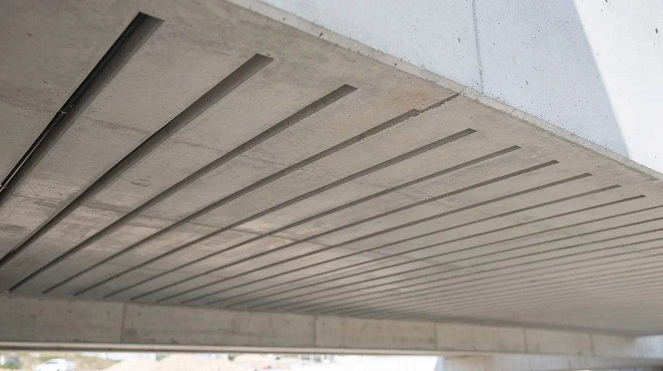
Near surface mounted (NSM) strengthening, also called near surface mounted reinforcement, refers to the installation of preformed fiber reinforced polymer bars, rods, or FRP strips into shallow grooves cut into the concrete cover of an existing member, bonded in place with structural epoxy. Unlike externally bonded FRP laminates or sheets that sit on the surface, NSM CFRP bars are partially embedded, which delivers a larger bonded surface area, better confinement by the surrounding concrete, and inherent protection from mechanical impact, UV exposure, and vandalism.
In dense urban settings such as Singapore, many reinforced concrete structures-bridge decks, podium slabs, carpark levels, hospital transfer plates-face increased load demands from change-of-use, heavier equipment, or code revisions. The technique of using NSM CFRP bars is suitable for retrofitting existing structures in these scenarios because it supports the broader goal of strengthening structures, adds flexural and shear strength without altering profile thickness, preserves headroom, and allows works to proceed in stages around live operations.
Key Components of an NSM CFRP System
An effective NSM system relies on four interdependent components working compositely with the existing internal steel reinforcement and concrete section.
-
CFRP bars/rods: Typically 8–12 mm diameter with sand- or grit-coated surfaces to improve bond. Tensile strengths range from approximately 1,800 to 2,400 MPa with an elastic modulus of roughly 150–200 GPa. As fiber reinforced polymer composites, they exhibit excellent corrosion resistance-CFRP is resistant to corrosion and environmental damage, enhancing durability far beyond traditional steel plates. Another FRP option is glass fiber reinforced polymer, but this article focuses on CFRP for flexural upgrades. NSM CFRP bars offer a higher strength-to-weight ratio compared to traditional materials, making handling and installation straightforward.
-
Epoxy adhesive: A two-component, structural-grade, thixotropic resin that bonds to both dry concrete and the CFRP surface. The adhesive’s glass transition temperature (Tg) must comfortably exceed the peak service temperatures expected in tropical climates-epoxies with Tg above 80–90 °C are typically specified for Singapore projects.
-
Saw-cut grooves: Cut to a depth roughly equal to the existing concrete cover minus a safety margin and wide enough to accommodate the bar plus an epoxy annulus. For example, in a US bridge deck retrofit, 11 mm diameter CFRP rods were placed in grooves 19 mm deep × 14 mm wide at 375 mm centres. Groove spacing and edge distances should comply with ACI 440.2R or CNR-DT 200 R2 recommendations.
-
Concrete substrate: Must have adequate compressive strength and be free of severe carbonation, chloride contamination, or delamination. A thorough concrete condition assessment before groove cutting is essential-the bond mechanism depends on the quality of the concrete/adhesive interface and the residual concrete cover.
These elements act together: once cured, the CFRP bar shares tensile force with the existing steel reinforcement, increasing the composite section’s resistance to bending without meaningful increase in self-weight.
Flexural Behaviour: Negative vs Positive Moment Regions
Flexural upgrades refer to enhancing a beam’s strength against bending and heavy loads. Understanding where tension develops in a deck cross-section determines where NSM bars must go:
-
Positive bending (sagging) occurs at mid-span regions of slabs, beams, and bridge decks, placing the soffit (bottom surface) in tension. Near surface mounted CFRP bars are therefore installed on the soffit for sagging zones, adding tensile capacity directly where it is needed.
-
Negative bending (hogging) develops over supports, columns, and diaphragms in continuous reinforced concrete beams and slabs. Here the top surface is in tension, so NSM bars must be placed near the top face-requiring coordination with waterproofing membranes, traffic surfacing, and drainage falls.
CFRP bars provide enhanced crack control and stiffness to reinforced concrete beams in both zones. Published tested beams showed significantly reduced crack widths versus control specimens, and strengthening with NSM CFRP improved cracking load by 69 %. In continuous RC beams strengthened with NSM rods in both hogging and sagging regions, flexural capacity improvements ranged from 42 % to 63 % relative to unstrengthened controls. In well-anchored flexural failures, the typical progression is steel yielding followed by concrete crushing, whereas the CFRP rod itself remains elastic until failure-there is no ductile yield plateau as with steel-so designers must ensure sufficient anchorage and detailing to prevent abrupt, brittle failures, especially in negative moment zones where concrete cover is often thinner.
This understanding of flexural behavior in both moment regions is the necessary foundation before moving to the practical design and detailing of NSM layouts.
Design Concepts for NSM CFRP Bars in Concrete Deck Upgrades
Translating the behavioural principles above into real design decisions requires a structured workflow for concrete deck upgrades and the flexural strengthening of RC members: assess what exists, identify the flexural deficit, compare strengthening options, then size and detail the NSM CFRP layout. In Singapore, this work typically references international guidance such as ACI 440.2R from the American Concrete Institute and relevant fib bulletins, with detailing widely used in practice for existing reinforced concrete upgrades, while satisfying local authority expectations from BCA, LTA, and JTC.
Assessing Existing Flexural Capacity and Deficits
Before sizing any NSM frp reinforcement, a thorough evaluation of the existing structure is essential. Key investigation steps include:
-
Review of original design drawings, as-built records, and any prior strengthening or structural defect rectification measures, noting reinforcement layout and concrete dimensions.
-
On-site structural inspections-similar in scope to periodic structural inspection (PSI) programmes-to identify cracking patterns, deflections, spalling, and corrosion of internal steel reinforcement.
-
Concrete cover survey and rebar scanning using ground-penetrating radar (GPR) and cover meters to locate existing reinforcement, post-tensioning ducts, and embedded services, confirming that adequate cover remains for groove cutting.
-
Material testing through rebound hammer surveys, ultrasonic pulse velocity, and core sampling to determine current concrete compressive strength, carbonation depth, and chloride content.
-
Analytical re-assessment of bending moments under current and projected loads-heavier data centre equipment, change from office to storage, additional Jersey barriers on bridge overhangs-mapping positive and negative moment demands against existing steel reinforcement capacity (reduced if corrosion is present).
The aim is to quantify shortfalls in both sagging and hogging moment capacities so that, for the strengthening of RC beams, the required NSM CFRP bar area can be sized rationally.
Choosing NSM CFRP Bars vs Alternative Strengthening Methods
Common alternatives for strengthening concrete structures include increasing section thickness (jacketing), externally bonded FRP sheets or laminates, steel plate bonding, external post-tensioning, and the NSM steel technique as a less corrosion-resistant option considered in some retrofit comparisons. NSM CFRP bars are often preferable in the following circumstances:
-
Limited headroom or strict architectural constraints where increasing slab thickness is impractical-the installation of NSM CFRP bars results in minimal aesthetic impact on structures since bars sit within the existing cover depth.
-
Exposure conditions demanding corrosion resistance-coastal viaducts, open-air carparks, and rooftop decks where steel plate bonding would introduce corrosion risk and externally bonded FRP reinforcement is susceptible to UV and impact damage. NSM CFRP bars provide better protection against environmental damage because they are shielded by the surrounding concrete.
-
Debonding-prone situations-external systems such as surface mounted CFRP strips and other EBR methods often suffer from premature debonding failures, especially in negative moment zones where peeling stresses are high. NSM CFRP strips increased strength by 79 % compared to EBR in direct comparisons, confirming that CFRP strips in NSM systems provide better bond characteristics than EBR.
AMAN Engineering Consultancy typically evaluates NSM against at least one alternative scheme during value engineering, weighing constructability, traffic diversion needs, lifecycle cost, and authority approval pathway to support RC flexural strengthening option selection through civil and structural design services.
Basic Design Parameters and Layout Considerations
While project-specific design must be carried out by a Professional Engineer, the following conceptual parameters guide early planning for reinforced concrete beams strengthened using NSM systems:
-
Bar diameter and spacing: Common practice uses 8–12 mm CFRP bars at 150–300 mm centres, refined by structural analysis. For prestressed NSM CFRP rods, this becomes a more specialised variant that needs separate design checks for force level, transfer, and serviceability. Low-strength concrete members (~17 MPa) can see proportionally larger percentage gains-up to ~52 %-while higher-strength concrete (~47 MPa) yields smaller relative improvements.
-
Development length and anchorage: Research indicates that NSM FRP development length should be at least approximately 80 times the bar diameter to ensure adequate bond. For NSM FRP strips, groove geometry and required bonded length vary with the reinforcement shape. Bars must extend beyond peak moment regions into lower-moment zones and must never terminate abruptly at high-shear locations.
-
Groove geometry: Width and depth are proportioned to the bar diameter, ensuring an adequate epoxy annulus while leaving sufficient residual concrete cover to prevent cover separation. Minimum edge distances follow ACI 440.2R and CNR-DT 200 R2 rules.
-
Coordination with congestion: Heavily reinforced transfer beams and post-tensioned decks require rebar scanning to avoid clashing; BIM modelling and structural analysis in Revit or Tekla helps visualise groove paths relative to ducts and reinforcement.
Key points to remember:
-
Always verify concrete cover sufficiency before committing groove locations.
-
Avoid overlapping stress fields when multiple parallel NSM bars are closely spaced.
-
Plan bar layout for both negative and positive moment continuity across supports.
With the design parameters established, the next step is translating these decisions into site procedures.
Practical Implementation: Embedding CFRP Rods in Saw-Cut Grooves
This section translates design intent into a step-by-step construction sequence, with emphasis on minimising disruption to live operations-hospitals, shopping malls, data centres, and carparks. Annotated photos or diagrams showing saw-cut grooves, bar placement, and epoxy infill on both the top (negative moment) and bottom (positive moment) surfaces of a deck are strongly recommended for project documentation and authority submissions.

Step-by-Step NSM Installation Procedure
Concrete cutting, bar placement, and adhesive bonding are core steps in the installation of near surface mounted frp in groove-cut concrete members. The sequence below applies to both soffit (positive moment) and top-face (negative moment) applications, with noted differences.
-
Surface preparation and layout marking: Using design drawings and rebar scan data, mark NSM bar lines on the soffit or top surface. Verify that groove lines do not conflict with existing steel bars, post-tensioning ducts, or embedded conduits.
-
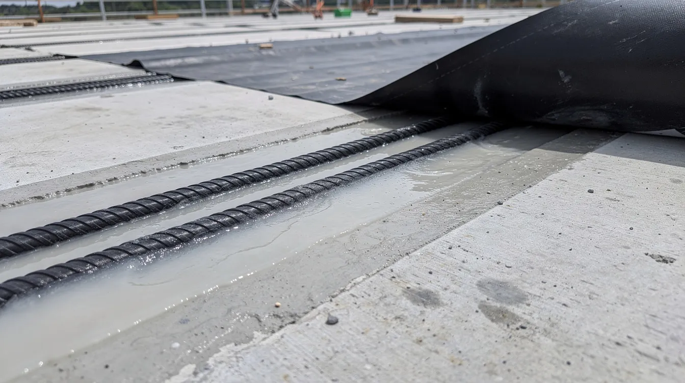
Saw-cutting grooves: Cut controlled-depth grooves along marked lines using diamond-blade concrete saws or angle grinders. Typical groove dimensions scale with bar diameter-for an 11 mm bar, grooves of approximately 19 mm depth × 14 mm width are representative. Employ dust suppression and extraction to maintain air quality, especially in enclosed carparks and occupied buildings.
-
Cleaning and conditioning grooves: Remove all dust, debris, and loose particles using compressed air and industrial vacuum. Ensure the substrate is dry and free from laitance or weak concrete. Proper groove preparation is essential for achieving bond performance in NSM applications.
-
Trial fitting of CFRP rods: Check that bars are straight and undamaged; insert into grooves to verify clearance. Cut rod segments to required lengths, including anchorage extensions beyond peak moment zones. Confirm curvature tolerance for any curved deck geometry.
-
Epoxy mixing and application: Mix the two-component epoxy strictly per manufacturer proportions. In Singapore’s tropical climate (ambient 30–35 °C, high humidity), working time is shortened-plan batch sizes accordingly. Partially fill grooves, avoiding air voids.
-
Placement of CFRP rods and epoxy topping-up: Press bars firmly into the epoxy bed to achieve full encapsulation. Top up with additional epoxy and finish flush or slightly recessed to accept future overlays or waterproofing. For concrete beams strengthened with NSM bars, full encapsulation and correct bar seating are what produce the intended bond response.
-
Curing and temporary support: Allow 24–72 hours of curing (adhesive- and temperature-dependent) before applying service loads. Monitor ambient temperature and humidity-epoxy Tg must not be approached during the cure window. Temporary shoring or load restrictions may be required while grooves are open and epoxy is uncured.
-
Surface reinstatement: Reinstate screeds, waterproofing membranes, fire protection coatings, or ceiling finishes. Where feasible, leave inspection access points so that NSM elements can be visually assessed during future structural inspections.
Quality control checks should be documented at key stages: groove dimension verification, epoxy batch records and cure temperature logs, bar alignment and spacing confirmation, and pull-off adhesion tests on trial panels to validate bond strength before full roll-out.
Anchorage, Termination, and Detailing at Supports
Many experimental programmes report that all NSM beams failed due to concrete cover separation, and strengthened beams failed prematurely because of debonding or cover separation in many test programmes, with failure typically initiating near bar ends or support regions where bond stresses concentrate. Common failures in NSM systems include premature debonding and concrete cover separation, making anchorage detailing the most critical aspect of a successful retrofit.
-
Extend bars beyond peak moment zones: NSM bars should continue past negative moment peaks across supports into lower-moment regions, with development lengths of at least 80 × bar diameter; these end-zone details should also be checked against shear strengthening demands at supports where flexure-shear interaction can govern.
-
Avoid termination in high-shear zones: Vertical crack opening displacement in shear-critical regions accelerates debonding; stagger terminations and shift them away from regions of concentrated shear.
-
Use deepened or fan-shaped grooves at ends: Where geometry permits, enlarge the groove at termination points to create epoxy pockets that reduce local bond stress. Published tests show that supplementary U-shaped steel hoops or anchor plates at bar ends improved ductility and delayed bond failure.
-
Add transverse reinforcement where splitting risk is high: If residual concrete cover above or below the groove is marginal, local jacketing or transverse FRP wraps can confine the cover and prevent splitting.
For bridge decks over roads in Singapore, access to the soffit or top surface may be restricted by LTA traffic management requirements, making it essential to plan anchorage zones that are reachable during phased lane closures. Support regions also need careful detailing because cracks, bond demand, and force transfer must remain compatible with the existing reinforcement cage, including the tension steel bars.
Coordinating Works with Operations, Safety, and Authority Requirements
NSM works in live facilities demand careful sequencing:
-
Operational continuity: Night works, weekend closures, or partial lane closures allow carparks, bridges, and podium slabs to remain partially serviceable. Hospitals and data centres may require restricted-access protocols and vibration monitoring during saw cutting.
-
Fire safety: If soffit fire protection is removed or altered during groove cutting, SCDF requirements apply. A fire safety engineering review determines whether temporary or permanent fire protection must be reinstated-especially relevant where exposed surface mounted FRP rods could be subject to heat.
-
Authority submissions: BCA and LTA require structural strengthening schemes to be endorsed by a PE, supported by calculations referencing acceptable standards (ACI 440.2R, Concrete Society TR 55, or equivalent). AMAN Engineering Consultancy prepares the full submission package-calculations, BIM models, method statements, and inspection-and-test plans-for BCA structural plan approval.
Despite thorough design and planning, recurring site-level issues demand anticipation. The following section addresses the most common challenges.
Common Challenges and Solutions in NSM CFRP Flexural Upgrades
Site conditions in existing buildings and infrastructure are rarely textbook-perfect. Reinforced concrete members may have corroded reinforcement, unknown services, or degraded concrete that complicates NSM installation. Each subsection below describes a specific problem and practical mitigation strategies drawn from real projects and experimental and analytical investigation findings.
Problem 1: Concrete Cover Separation and CFRP Debonding
Symptoms: Sudden loss of CFRP contribution, longitudinal cracking along the groove line, concrete cover splitting near supports or concentrated load points. In laboratory studies, all the strengthened beams that were not properly anchored failed by concrete cover separation rather than CFRP rupture-the bars reached only approximately 40–45 % of their rupture strain before debonding.
Solutions:
-
Ensure sufficient residual cover above or below the groove and respect minimum groove spacing rules (e.g. CNR-DT 200 R2 specifies groove spacing ≥ 3 × groove width and edge distance ≥ 3 × groove width).
-
Lengthen grooves well into lower-moment zones, extending at least 80 bar diameters beyond the theoretical cut-off point.
-
Adopt conservative design bond stresses and cross-check against predicted crack patterns from structural analysis.
-
Conduct pull-off adhesion tests or build trial panels to validate real bond performance before commencing production work.
Problem 2: Limited Access to Deck Surfaces (Top or Bottom)
Examples: Bridge decks where traffic cannot be diverted for extended periods; building slabs over occupied spaces where soffit access is heavily constrained by ceiling systems, sprinkler piping, or low clearance.
Solutions:
-
Stage works with partial closures and deploy movable gantries or scaffolding platforms to reach soffit areas progressively.
-
Prioritise NSM on the more accessible face-top vs bottom-based on whether negative or positive moment strengthening is the more critical deficit.
-
In locations where neither face is fully accessible, combine NSM CFRP with local external post-tensioning or steel plate strengthening as a hybrid scheme, optimising coverage and minimising total access time.
Problem 3: Integrating NSM Bars with Existing Services and Finishes
Challenges: Embedded conduits, sprinkler pipes, ceiling grid systems, waterproofing membranes, and floor tiles can obstruct groove placement. Saw cutting risks damaging concealed services.
Solutions:
-
Perform comprehensive GPR scanning and cover meter surveys to map reinforcement and services before finalising the NSM layout.
-
Adjust bar spacing or switch to smaller-diameter bars to navigate congested regions while still meeting the required flexural capacity.
-
Coordinate with M&E consultants and architects to sequence removal and reinstatement of finishes and services around strengthening works.
-
Use BIM models (Revit, Tekla) generated through structural modelling services to visualise the CFRP layout relative to services, especially in complex decks within data centres and hospitals.
Problem 4: Ensuring Long-Term Durability in Tropical and Coastal Environments
Concerns: Singapore’s climate-average relative humidity 76–90 %, ambient temperatures of 30–35 °C-challenges epoxy adhesives. Research shows that ambient temperatures approaching or exceeding the epoxy’s Tg can reduce bond strength by up to approximately 58.9 % compared to baseline. Moisture ingress along grooves in exposed top surfaces compounds the risk.
Mitigation:
-
Select epoxies with Tg above 80–90 °C and proven performance data under high-humidity tropical conditions. Studies in tropical Malaysia confirm that bond performance in FRP systems degrades under outdoor wet/dry cycles, though the embedded nature of NSM provides inherent shielding that externally bonded FRP reinforcement lacks.
-
Detail surface sealers or protective overlays over NSM grooves at exposed top surfaces; restore waterproofing membranes meticulously to prevent ponding water from entering groove lines.
-
Integrate NSM elements into the facility’s regular inspection regime-AMAN’s PSI and PFI services can include periodic crack mapping, deflection monitoring, and visual bond assessment of strengthened reinforced concrete zones.
-
For severe exposure (coastal viaducts, sulfate-laden environments), consider parabolic NSM CFRP rope profiles with vertical or lateral dowels, which have demonstrated retained stiffness and load capacity even after aggressive chemical exposure.
With these challenges addressed through proper design, material selection, and inspection planning, NSM CFRP flexural strengthening delivers reliable, long-term performance.
Conclusion and Next Steps
Near surface mounted CFRP bars embedded in saw-cut grooves are a powerful, relatively non-intrusive method to upgrade both negative and positive bending moment capacities of existing concrete decks. NSM beams increased ultimate load by up to 92 %, and even modest FRP ratios can shift failure modes from brittle shear to flexure-dominated behaviour with dramatically improved ductility. Prestressed NSM CFRP bars can increase ultimate load by 61–97 %, and prestressing NSM CFRP enhances stiffness and reduces deflection for structures where serviceability is the governing criterion. NSM reinforcement is less vulnerable to environmental damage than EBR, making it particularly well suited to Singapore’s tropical climate, and NSM techniques require less surface preparation than EBR methods-lowering site disruption.
Immediate next steps for different reader types:
-
Asset owners and facility managers: Commission a condition survey and flexural capacity review of critical decks where higher loads or change of use is planned. Early identification of moment deficits allows time for cost-effective NSM solutions rather than emergency repairs.
-
Contractors: Engage early with a PE and a consultancy experienced in concrete strengthening-such as AMAN Engineering Consultancy-to assess feasibility, methodology, and staging for NSM works, including trial mock-ups to validate bond performance on representative substrates.
-
Architects and designers: Incorporate strengthening allowances and access provisions into refurbishment schemes and BIM models so that groove paths, anchorage zones, and service relocations are planned rather than improvised.
Related topics worth exploring next:
-
Externally bonded FRP systems – when EB CFRP sheets or laminates may complement or substitute for NSM in specific zones.
-
Prestressed near surface mounted CFRP techniques – CFRP can improve serviceability performance when prestressed during installation, and the prestressing level affects ductility in NSM CFRP beams, opening further optimisation possibilities.
-
Fire safety engineering for FRP strengthened reinforced concrete – ensuring compliance with SCDF requirements when protective layers are modified.
AMAN Engineering Consultancy Pte Ltd supports end-to-end delivery of NSM CFRP flexural upgrades: from structural assessment and PE endorsement through authority submissions, BIM coordination, and on-site construction supervision-helping owners, developers, and contractors achieve compliant, durable upgrades to their reinforced concrete structures.
Additional Resources
The references below provide concise starting points for further reading and project planning. They are not exhaustive and do not replace project-specific PE advice.
-
ACI 440.2R – The American Concrete Institute’s guide for design and construction of externally bonded FRP systems, widely cited by BCA’s Approved Documents as an acceptable standard for FRP strengthening of reinforced concrete members. Covers both EB and NSM detailing principles for strengthening of RC beams and related Near Surface Mounted FRP applications.
-
CNR-DT 200 R2 (2025 edition) – The Italian National Research Council’s updated design guide, which now includes explicit rules for NSM groove spacing, edge distances, and bond verification-particularly useful for projects where ACI 440.2R provisions need supplementing for strengthening of RC beams and related Near Surface Mounted FRP applications.
-
fib Bulletin series on FRP reinforcement – International guidance on frp materials, bond models, and durability considerations for strengthening concrete members with composite materials, including strengthening of RC beams and related Near Surface Mounted FRP applications; named researchers in this area include el hacha r.
-
Project documentation templates: A well-prepared NSM project package includes method statements, inspection-and-test plans (ITPs) with hold points for groove verification, epoxy batch testing, and bar alignment, plus as-built records showing actual bar positions and groove depths.
-
BIM integration: AMAN’s workflow integrates NSM strengthening details-groove paths, bar layouts, anchorage zones-into Revit and Tekla 3D models for clash detection and coordinated authority drawing submissions.
-
Local Singapore codes and circulars: SS 674:2021 (Design Guide for Fibre-Reinforced Concrete Structures) and BCA Approved Document V7-06 reference acceptable FRP design standards. Designers should consult the latest BCA circulars and engage a Professional Engineer for project-specific design, endorsement, and submission.