
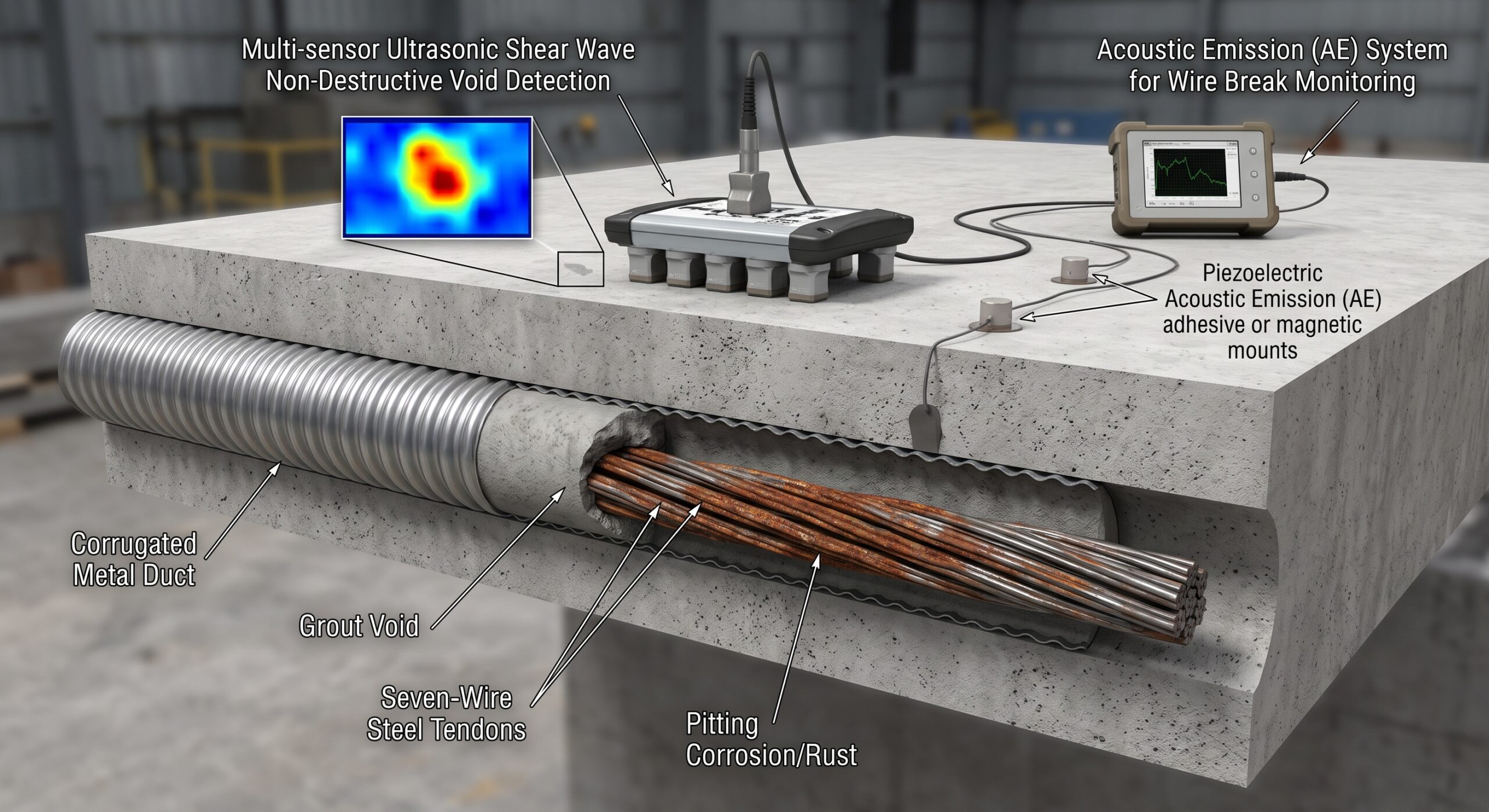
Structural Building Inspection & Assessment: PT Slab Tendon Corrosion & Void Detection
Introduction to Structural Assessment
Post-tensioned concrete slabs transform modern architectural and structural engineering completely. These advanced systems enable incredibly long, unsupported architectural spans1. High-strength steel tendons apply active compressive forces to the concrete2. This continuous active compression resists massive external tensile service loads3. It prevents concrete cracking and controls structural deflection very effectively1.
However, these complex structural systems remain highly vulnerable to deterioration. Comprehensive structural building assessment is absolutely vital for public safety. A specialized post-tensioned slab inspection reveals hidden internal structural defects2. Undetected tendon corrosion eventually causes catastrophic and sudden structural failure1. Regular technical evaluations prevent sudden collapses and costly emergency repairs.
This report examines critical high-risk failure modes in post-tensioned systems. It analyzes advanced methods for identifying severe tendon corrosion accurately. It explores the dangerous loss of prestress in structural elements. The analysis covers void detection in grouted duct systems extensively. Finally, it reviews advanced Acoustic Emission Monitoring techniques for real-time assessment.
High-Risk Failure Modes in PT Concrete Slabs
Post-tensioned structures face unique and severe high-risk failure modes. The primary and most dangerous threat is advanced tendon corrosion1. Steel tendons operate under extreme tensile stress continuously during service4. This sustained high stress accelerates various environmental degradation mechanisms significantly5.
Bonded Versus Unbonded Systems
System design dictates the specific consequences of a tendon failure. Bonded systems use cementitious grout inside the protective tendon ducts1. The grout bonds the steel directly to the surrounding concrete1. If a bonded wire breaks, force redistributes locally through grout1. The surrounding grout contains the failure to a limited area1.
Unbonded systems use greased tendons inside protective plastic sheathing conduits1. These individual strands move freely within the hardened concrete slab1. A single wire break causes a complete loss of prestress1. The tension releases instantly along the entire tendon length rapidly1. This makes unbonded slabs highly susceptible to sudden capacity loss.
Tendon Metallurgy and Vulnerability
Prestressing tendons possess specific metallurgical properties that dictate their vulnerability. Modern post-tensioning relies on seven-wire steel strands6. These strands conform strictly to the ASTM A416 manufacturing standard. Grade 270 strand provides a minimum ultimate tensile strength of 1860 MPa.
The steel contains a high carbon content near 0.8 percent7. Manufacturers cold-draw the steel through progressively smaller dies during production2. Cold drawing creates a heavily deformed pearlitic microstructural grain alignment2. This unique microstructure gives the steel its exceptional tensile strength2. However, this exact microstructure creates high sensitivity to environmental hydrogen2.
Environmental Corrosion Mechanisms
Moisture and chloride ingress drive the primary degradation and corrosion8. Water easily enters through poorly sealed construction joints and cracks2. Defective anchorage zones also allow rapid moisture penetration over time2. Chloride ions destroy the protective alkaline passive layer on steel8.
This destruction initiates severe localized pitting corrosion along the tendon8. Pitting rapidly reduces the cross-sectional area of the steel strand8. This cross-sectional reduction inevitably lowers the effective prestress force5. Reduced force leads to excessive deflection and structural capacity loss1.
Stress Corrosion Cracking and Hydrogen Embrittlement
Hydrogen embrittlement represents a catastrophic high-risk structural failure mode9. High-strength steel absorbs atomic hydrogen during localized corrosion reactions2. Galvanic coupling between steel strands and galvanized ducts produces hydrogen10.
This absorbed hydrogen drastically reduces the steel fracture toughness properties3. The internal hydrogen stresses weaken the basic iron-iron atomic bonds3. Sudden, brittle wire cracking occurs without any prior visual warning2.
Stress corrosion cracking (SCC) also plagues high-strength steel tendons3. SCC requires a highly corrosive environment and continuous tensile stress11. The toxic combination causes microscopic cracks to propagate very rapidly. These growing cracks eventually precipitate a sudden brittle tendon failure12.
| Failure Mode | Primary Cause | Structural Consequence |
| Pitting Corrosion | Chloride ion attack | Cross-section reduction |
| Hydrogen Embrittlement | Atomic hydrogen absorption | Sudden brittle fracture |
| Stress Corrosion Cracking | Sustained stress and corrosive media | Rapid crack propagation |
| Anchorage Failure | Moisture pooling at member ends | Complete loss of tension |
Identifying Tendon Corrosion and Loss of Prestress
Early detection of internal tendon corrosion remains extremely challenging technically. Visual inspections alone cannot predict imminent structural collapse reliably ever2. Outward signs of distress appear long after internal deterioration begins1.
Visual Indicators of Prestress Loss
Engineers look for specific surface clues during a visual inspection. New cracks running perpendicular to the tendon path indicate problems1. These specific cracks suggest a localized loss of prestress force1. White efflorescence along cracks indicates active water migration through concrete1. This migrating water may be reaching the embedded steel tendons1.
Excessive slab deflection signals a severe loss of prestress capacity1. Noticeable sagging indicates that multiple embedded tendons have failed completely1. Concrete spalling at slab edges exposes corroded metallic anchorage hardware1. Compromised anchorages cannot transfer the full prestress force safely anymore1.
Electrochemical Corrosion Assessment
Engineers use specialized electrochemical testing for early corrosion identification processes. Half-cell potential (HCP) mapping detects the likelihood of active corrosion13. This method follows the standard ASTM C876 testing guidelines strictly.
A copper-copper sulfate reference electrode moves across a concrete surface. It measures the electrical potential relative to the embedded steel. A high-impedance voltmeter records these subtle electrical voltage differences accurately.
| HCP Reading (mV vs CSE) | Probability of Active Corrosion |
| Less negative than -200 mV | 10% Probability (Low Risk) |
| -200 mV to -350 mV | Uncertain (Moderate Risk) |
| More negative than -350 mV | 90% Probability (High Risk) |
Potentials more negative than -350 mV indicate severe corrosion activity. Readings above -200 mV suggest a very low corrosion probability. However, concrete moisture content and carbonation alter these readings significantly14.
Dry concrete produces falsely positive readings regardless of actual corrosion. Carbonation shifts electrical potentials negatively by up to 400 millivolts. Chloride contamination produces highly negative potentials in wet concrete environments.
Linear Polarization Resistance Testing
Linear polarization resistance (LPR) testing measures the actual corrosion rate15. This technique quantifies instantaneous metal loss in micrometers per year. It shifts the baseline steel potential slightly by 20 millivolts.
The system then measures the resulting balancing electrical corrosion current. Faraday’s Law calculates the metal section loss from this current. LPR provides critical data for precise structural service life prediction. It reliably differentiates active corrosion hot spots from passive zones.
Void Detection in Grouted Duct Systems
Bonded post-tensioned systems rely entirely on grout for corrosion protection16. The alkaline grout passivates the steel against environmental chemical attacks17. Unfortunately, incomplete grouting frequently leaves voids inside the tendon ducts2. These voids leave sections of the tendon completely exposed1.
Causes of Grout Voids
Bleed water accumulation is a primary cause of grout voids18. Excess water rises to the highest tendon profile elevation points19. This fluid water flows through interstitial spaces between wire strands19. It eventually reabsorbs or evaporates, leaving a permanent empty void19.
Grout segregation creates soft, chalky grout zones lacking structural strength19. Soft grout absorbs moisture and promotes rapid localized steel corrosion19. High water-to-cement ratios exacerbate both bleeding and segregation issues significantly19. The PTI M55.1-12 standard strictly limits water-cement ratios below 0.4520.
| Grout Property | Standard Requirement | Standard Reference |
| Maximum w/c ratio | 0.45 by weight | PTI M55.1-12 |
| Compressive Strength | Minimum 34.5 MPa (5,000 psi) | PTI M55.1-12 |
| Maximum Bleed | 0% (wick-induced test) | ASTM C940 Modified |
| Maximum Chloride | 0.08% by weight of cement | PTI M55.1-12 |
Impact-Echo Testing for Void Detection
Engineers use advanced nondestructive testing to detect hidden duct voids19. The impact-echo (IE) method is highly effective for void detection19. Impact-echo utilizes short mechanical impacts on the exterior concrete surface21. These physical impacts generate low-frequency elastic stress waves internally22.
The stress waves reflect off internal boundaries and duct voids23. A displacement transducer records the surface response continuously during testing24. Engineers analyze the frequency spectrum of these reflected wave signals. They utilize a Fast Fourier Transform to process the raw data.
Intact concrete produces a distinct, predictable dominant frequency spectral peak25. A downward shift in this dominant frequency strongly indicates a void24. Impact-echo works effectively for concrete structures up to 600 mm. Automated impact-echo scanners allow for rapid, continuous structural testing applications. Scanning resolution typically achieves measurements every 25 millimeters along ducts.
Ultrasonic Shear Wave Tomography
Ultrasonic shear wave tomography provides advanced 3D void imaging capabilities26. The MIRA system is widely utilized for this specific application27. It features an array of dry-point contact shear wave transducers29. These specialized sensors do not require any messy liquid couplants30.
The system emits ultrasonic pulses typically centered around 50 kHz31. MIRA employs the synthetic aperture focusing technique (SAFT) processing algorithm28. This complex algorithm reconstructs detailed cross-sectional images of the concrete32. It utilizes pulse peak delays to increase spatial imaging accuracy significantly.
The resulting tomographs clearly identify ungrouted sections within tendon ducts33. Ultrasonic tomography accurately maps honeycombing, delaminations, and deep internal cracks33. It provides volumetric imaging from a single accessible concrete surface34. MIRA reliably measures concrete thickness and locates embedded structural elements.
Limitations of Ground Penetrating Radar
Ground penetrating radar (GPR) is another common nondestructive testing tool35. It emits high-frequency electromagnetic waves into the solid concrete structure36. GPR successfully locates embedded rebar and post-tensioning duct alignments accurately.
However, electromagnetic waves cannot penetrate through metallic duct walls effectively37. Strong wave reflections from the steel completely shield internal defects. Therefore, radar cannot reliably detect grout voids inside steel ducts. GPR only detects voids within plastic or fiberglass duct systems38.
| NDT Method | Primary Signal Type | Duct Void Detection Capability |
| Impact-Echo | Mechanical Stress Wave | High (Frequency shift analysis) |
| Ultrasonic Tomography | Shear Wave (50 kHz) | Very High (3D SAFT imaging) |
| Ground Penetrating Radar | Electromagnetic Wave | Poor (Blocked by metal ducts) |
| Half-Cell Potential | Electrochemical | None (Detects active corrosion) |
Acoustic Emission Monitoring
Acoustic emission (AE) monitoring provides real-time structural health assessment data39. This passive NDT method detects transient elastic stress waves continuously40. Rapid release of strain energy generates these unique stress waves37. Crack propagation, corrosion activity, and wire breakage emit strong signals40.
Principles of AE Sensing
Piezoelectric sensors attach directly to the exterior concrete structure surface42. They capture high-frequency acoustic emission events as they physically occur. The optimal working frequency range for concrete is 30-100 kHz43. Higher frequencies attenuate too rapidly within the heterogeneous concrete matrix.
Wire break signals exhibit massive amplitudes and distinct frequency signatures44. A steel wire break generates amplitudes often exceeding 80 decibels37. It releases a very high amount of energy almost instantaneously41. AE monitoring successfully captures these specific events during normal operations.
Analyzing AE Data: The b-value
Engineers analyze acoustic emission data using advanced statistical evaluation parameters45. The b-value analysis evaluates the frequency-magnitude distribution of emission events46. This concept originates from Gutenberg and Richter earthquake seismology models.
Micro-cracking produces many low-amplitude acoustic emission events within concrete47. This distinct pattern results in a relatively high calculated b-value. Macro-cracking generates fewer events but with much higher peak amplitudes. Therefore, a rapidly dropping b-value indicates imminent catastrophic structural failure45. The b-value serves as a highly reliable early warning damage indicator49.
The Ib-value improves upon traditional b-value metrics for concrete evaluation. It calculates the statistical slope using the most recent events. This transient feature updates continuously with every new recorded structural hit.
The Kaiser Effect and Felicity Ratio
The Felicity ratio helps evaluate structural damage under complex cyclic loads50. The Kaiser effect governs the fundamental acoustic emission load history. It states materials emit noise only upon exceeding previous maximum loads.
If acoustic emissions occur before reaching the previous peak load, damage exists51. This premature emission signifies that the fundamental Kaiser effect is broken. The ratio of this new emission load to the prior peak is calculated. This specific calculation is universally known as the Felicity ratio.
A Felicity ratio below 1.0 indicates severe, progressive internal structural damage. It proves that the structure cannot sustain previously applied safe loads. Structural engineers use this ratio to quantify irreversible damage accumulation early52.
| AE Parameter | Structural Meaning | Indicator of Failure |
| Signal Amplitude | Intensity of the fracture event | Sustained >80 dB readings |
| b-value | Ratio of micro to macro cracks | Rapidly decreasing statistical value |
| Felicity Ratio | Violation of the Kaiser effect | Load ratio dropping below 1.0 |
| Cumulative Energy | Total damage accumulated over time | Exponential strain energy increase |
Machine Learning in AE Monitoring
Machine learning significantly improves complex acoustic emission data analysis procedures53. Convolutional neural networks classify complex acoustic emission waveforms highly accurately54. These advanced algorithms separate actual wire breaks from routine environmental noise.
Pattern recognition algorithms identify specific anomalies indicating stress corrosion cracking55. They isolate the exact signal waveforms matching layered cable fracturing39. Machine learning enables reliable, fully automated structural health monitoring systems. This drastically reduces false positive alarms in inherently noisy bridge environments.
Distributed Acoustic Sensing (DAS)
Distributed acoustic sensing is an emerging continuous structural monitoring technology. It uses standard optical fibers as highly dense continuous vibration sensors56. DAS utilizes Rayleigh backscattering to detect dynamic strain and structural vibrations.
A single laser interrogator monitors fiber lengths exceeding 50 kilometers57. This provides continuous spatial coverage without any monitoring blind spots58. DAS effectively detects post-tensioned wire breaks in large-scale modern infrastructure. It provides a highly cost-effective alternative to traditional discrete AE sensors.
The passive optical nature of DAS makes it immune to electromagnetic interference44. It tracks event propagation accurately along the entire length of the fiber. Neural network post-processing enhances the signal-to-noise ratio of DAS data significantly59.
Repair and Mitigation Strategies
A post-tensioned slab inspection often identifies critical areas requiring immediate repair. Proper remediation prevents further tendon corrosion and restores lost structural capacity.
Vacuum Grouting Procedures
Identified duct voids require immediate repair to prevent severe steel corrosion60. Vacuum grouting is the industry preferred repair method for PT ducts. This technique effectively removes trapped air from the internal structural void61.
Technicians drill small access holes directly into the precisely located void. They carefully avoid damaging the highly stressed exposed steel wire strands. A specialized vacuum pump connects securely to one of the holes. It lowers the internal pressure to approximately negative 0.8 bar.
Low-viscosity cementitious grout is injected through a second access hole. The applied vacuum forcefully draws this fluid grout completely inward. This process completely encapsulates the exposed steel tendon strand with grout. Vacuum grouting restores the essential alkaline corrosion protection layer perfectly.
External Post-Tensioning Retrofits
Severely corroded tendons may require external post-tensioning structural retrofit interventions. External post-tensioning restores the lost structural flexural capacity safely and effectively. External tendons apply active compressive loads directly to the damaged member.
This technique strengthens failing slabs without requiring major facility operational shutdowns. Tendons anchor to the exterior faces of the existing concrete elements. This allows for easy visual inspection and future tendon replacement capabilities.
Regulatory Standards and Compliance
Adherence to strict engineering standards ensures post-tensioned structure safety globally. The Post-Tensioning Institute provides comprehensive evaluation and structural repair guidelines. PTI DC80.3-12 guides the evaluation of unbonded post-tensioned concrete structures strictly.
In Singapore, the Building and Construction Authority mandates strict inspection regimes62. The Periodic Structural Inspection (PSI) regime ensures long-term commercial building safety63. Residential buildings undergo mandatory structural inspections every ten years exactly64. Non-residential buildings face a more frequent five-year inspection regulatory cycle.
Structural engineers must conduct rigorous visual and nondestructive testing assessments routinely65. They evaluate post-tensioned slabs according to the SS EN 1992 standard33. This Eurocode standard governs the design of modern prestressed concrete structures19. Compliance with these rigorous standards prevents catastrophic structural failures and tragedies.
Conclusion
A post-tensioned slab inspection is a highly complex engineering endeavor always. It requires a deep understanding of unique high-risk structural failure modes. Tendon corrosion, hydrogen embrittlement, and loss of prestress threaten structural integrity. Visual inspections provide only limited clues regarding internal structural health conditions.
Advanced nondestructive testing is essential for accurate duct void detection processes. Impact-echo and ultrasonic shear wave tomography locate dangerous grouted duct voids. Ground penetrating radar assists but struggles with metallic duct signal shielding.
Acoustic emission monitoring tracks active crack propagation and catastrophic wire breaks. The b-value and Felicity ratio provide early warnings of progressive damage. Machine learning enhances data interpretation, separating true defects from background noise. Distributed acoustic sensing provides cost-effective, continuous monitoring over vast structural distances.
Proactive structural building assessment ensures the longevity of post-tensioned concrete infrastructure. Timely repairs using vacuum grouting restore essential tendon alkaline corrosion protection. Through diligent inspection and advanced technology, engineers prevent catastrophic structural failures successfully.
Works cited
- Management of post-tensioned concrete bridges, https://www.standardsforhighways.co.uk/tses/attachments/e210c524-85a5-4246-974b-400985c28f81?inline=true
- Post-Tensioning Institute > Education > PT Applications > Repair, https://www.post-tensioning.org/education/ptapplications/repair.aspx
- When Post Tension Systems Start Failing – EngineeringCivil.org, https://engineeringcivil.org/articles/civil-engineering/when-post-tension-systems-start-failing/
- Probabilistic Models for the Tensile Strength of Corroding Strands in, https://ascelibrary.org/doi/10.1061/%28ASCE%29MT.1943-5533.0000096
- Assessment of corroded prestressed and post- tensioned concrete, https://lirias.kuleuven.be/retrieve/627351
- Post-Tensioning (PT) in Concrete Structures | TarmacView, https://www.tarmacview.com/glossary/post-tensioning/
- Prestressing Tendon | TarmacView, https://www.tarmacview.com/glossary/tendon/
- How to Inspect Post-Tension Tendons? – RTF | Rethinking The Future, https://www.re-thinkingthefuture.com/article/how-to-inspect-post-tension-tendons/
- Hydrogen Embrittlement of Steels for Prestressing Concrete: The FIP, https://www.researchgate.net/publication/237981169_Hydrogen_Embrittlement_of_Steels_for_Prestressing_Concrete_The_FIP_and_DIBt_Tests
- Identification of the Mechanisms that Produce Hydrogen … – ROSA P, https://rosap.ntl.bts.gov/view/dot/68944/dot_68944_DS1.pdf
- Influence of Material and Processing On Stress Corrosion Cracking, https://www.scribd.com/document/694801275/Influence-of-material-and-processing-on-stress-corrosion-cracking-of-prestressing-steel-FIB-2003
- Corrosion of Prestressing Steels and Its Mitigation, https://www.pci.org/PCI_Docs/Publications/PCI%20Journal/1992/September/Corrosion%20of%20Prestressing%20Steels%20and%20Its%20Mitigation.pdf
- Corrosion of Reinforcement in Concrete Structures – TarmacView, https://www.tarmacview.com/glossary/corrosion-defect/
- (PDF) Accelerated artificial corrosion monitoring of reinforced, https://www.researchgate.net/publication/273770302_Accelerated_artificial_corrosion_monitoring_of_reinforced_concrete_slabs_using_the_half-cell_potential_method
- Understanding the Rates of Corrosion in Concrete Structures, https://www.structuremag.org/article/understanding-the-rates-of-corrosion-in-concrete-structures/
- Corrosion-Induced Major Tendon Failures in Post-Tension (PT, https://highways.dot.gov/media/56751
- Corrosive Bleed Water in Post-Tensioned Tendons, https://www.pci.org/PCI/News-Events/Papers/2002/Buildings-Materials/Corrosive-Bleed-Water-in-Post-Tensioned-Tendons.aspx?WebsiteKey=5a7b2064-98c2-4c8e-9b4b-18c80973da1e
- PTI Journal Technical Session Papers – Post-Tensioning Institute, https://www.post-tensioning.org/Portals/13/Files/PDFs/Publications/Reprints/2017%20December/Haixue-reprint.pdf
- SS EN 1992-1-1:2024: Singapore PE’s Guide to Eurocode 2, https://www.aectechnicalsg.com/ss-en-1992-1-12024-singapore-pes-guide-to-the-second-generation-eurocode-2/
- Grouting of Post-Tensioning Ducts – TarmacView, https://www.tarmacview.com/glossary/grouting/
- Impact Echo Testing (IE) | TRSC, https://trsc.au/technologies/impact-echo
- Impact-Echo Testing | TarmacView, https://www.tarmacview.com/glossary/impact-echo/
- (PDF) The Impact-Echo Method: An Overview1 – ResearchGate, https://www.researchgate.net/publication/243776112_The_Impact-Echo_Method_An_Overview1
- Impact-Echo Scanning for Grout Void Detection in Post-tensioned, https://www.olsoninstruments.com/wp-content/uploads/IES_forGrountVoidDetection_PT-BridgeDucts_OLSON.pdf
- Experimental and Numerical Studies on Nondestructive Evaluation, https://www.researchgate.net/publication/269280162_Experimental_and_Numerical_Studies_on_Nondestructive_Evaluation_of_Grout_Quality_in_Tendon_Ducts_Using_Impact-Echo_Method
- Progressive Investigation and Void Detection of Post-Tensioned, https://www.tac-atc.ca/wp-content/uploads/ward.pdf
- Condition Assessment of PC Tendon Duct Filling by Elastic Wave, https://pmc.ncbi.nlm.nih.gov/articles/PMC3967818/
- Imaging Concrete Structures with Ultrasonic Shear Waves … – MDPI, https://www.mdpi.com/2412-3811/8/3/53
- A1040 MIRA 3D – Ultrasonic Concrete Testing – ACS Group, https://acs-international.com/instruments/ultrasonic-pulse-echo-tomography-systems-mira/a1040-mira-3d-thickness-measurement-rebar-and-flaw-detection/
- ULTRASONIC IMAGING FOR CONCRETE INFRASTRUCTURE, https://rosap.ntl.bts.gov/view/dot/32225/dot_32225_DS1.pdf
- unconventional applications of a1040 mira tomograph – ResearchGate, https://www.researchgate.net/publication/330716844_UNCONVENTIONAL_APPLICATIONS_OF_A1040_MIRA_TOMOGRAPH
- 3D Internal Visualization of Concrete Structure Using Multifaceted, https://pmc.ncbi.nlm.nih.gov/articles/PMC8512131/
- Approveddocument.pdf – Building and Construction Authority, https://www.bca.gov.sg/publications/BuildingControlAct/others/Approveddocument.pdf
- NDT of Concrete in Practice – Acoustic Control Systems, https://acs-international.com/technology/ndt-of-concrete-in-practice/
- Inspection of reinforced concrete structures using ground, https://jksus.org/inspection-of-reinforced-concrete-structures-using-ground-penetrating-radar-experimental-approach/
- 7 NDT Methods for Accurate Corrosion Evaluation in Concrete, https://fprimec.com/7-ndt-methods-for-accurate-corrosion-evaluation-in-concrete-structures/
- A Study on the Detection of Internal Defect Types for Duct Depth of, https://www.mdpi.com/1996-1944/14/14/3931
- Identifying voids in plastic ducts in post-tensioning prestressed, https://www.researchgate.net/publication/248541572_Identifying_voids_in_plastic_ducts_in_post-tensioning_prestressed_concrete_members_by_resonant_frequency_of_impact-echo_SIBIE_and_tomography
- (PDF) Assessing Corrosion Damage in Posttensioned Concrete, https://www.researchgate.net/publication/283028582_Assessing_Corrosion_Damage_in_Posttensioned_Concrete_Structures_Using_Acoustic_Emission
- Acoustic Emission Monitoring | TarmacView, https://www.tarmacview.com/glossary/acoustic-emission-monitoring-for-structural-inspection/
- Acoustic Emission Source Characterization of Fatigue Crack, https://scispace.com/pdf/acoustic-emission-source-characterization-of-fatigue-crack-4njbvxd38n.pdf
- Acoustic Emission Sensing for Crack Monitoring in Prefabricated, https://scispace.com/pdf/acoustic-emission-sensing-for-crack-monitoring-in-2olu4cn739.pdf
- Acoustic Emission Testing of Concrete Structures, https://www.techknowserv.com/post/acoustic-emission-testing-of-concrete-structure
- Continuous acoustic monitoring of grouted post-tensioned concrete, https://www.researchgate.net/publication/242751129_Continuous_acoustic_monitoring_of_grouted_post-tensioned_concrete_bridges
- An Experimental Study of Acoustic Emission Monitoring on Cement, https://geopersia.ut.ac.ir/article_89817_3080b80dcbd0d9ab7a48409ee365f3aa.pdf?lang=fa
- b-value of plain concrete beams based on AE Quanta, https://framcos.org/wp-content/uploads/framcos-papers/b_value_of_plain_concrete_beams_based_on_AE_Quanta.pdf
- Acoustic emission characterization of the fracture process in fibre, https://mss-nde.lab.uoi.gr/publications-pdf/journal-papers/2011/2011-Acoustic%20emission%20characterization%20of%20the%20fracture%20process%20in%20fibre%20reinforced%20concrete.pdf
- Acoustic Emission Analysis of Fracture and Size Effect in … – MDPI, https://www.mdpi.com/2076-3417/12/7/3489
- B-Value Analysis of AE Signal Subjected to Stepwise Loading, https://www.researchgate.net/publication/278180324_B-Value_Analysis_of_AE_Signal_Subjected_to_Stepwise_Loading
- Part Qualification Methodology for Composite Aircraft Components, https://www.mdpi.com/2076-3417/8/9/1490
- Development of Acoustic Emission Evaluation Method for Repaired, https://www.eng.auburn.edu/files/centers/hrc/930-601-11.pdf
- Acoustic Emission Mechanisms and Fracture … – PMC – NIH, https://pmc.ncbi.nlm.nih.gov/articles/PMC12898633/
- Machine learning-assisted acoustic emission localization of, https://www.researchgate.net/publication/410275132_Machine_learning-assisted_acoustic_emission_localization_of_simulated_wire-break_events_in_prestressed_strands_of_high-speed_railway_box_girders
- Post-tensioned wire breaks detection method using distributed, https://openlib.tugraz.at/download.php?id=68ac07c47730a&location=browse
- Integration of Pattern Recognition and Machine Learning with the, https://www.preprints.org/manuscript/202607.2398
- Research Advances on Distributed Acoustic Sensing Technology for, https://www.mdpi.com/2304-6732/12/3/196
- Fiber Optic Distributed Acoustic Sensing Market – Dataintelo, https://dataintelo.com/report/fiber-optic-distributed-acoustic-sensing-market
- openlib – TU Graz, https://openlib.tugraz.at/13th-international-conference-on-structural-health-monitoring-of-intelligent-infrastructure-shmii-13-2025
- (PDF) Enhancing the Distributed Acoustic Sensors’ (DAS, https://www.researchgate.net/publication/370205580_Enhancing_the_Distributed_Acoustic_Sensors’_DAS_Performance_by_the_Simple_Noise_Reduction_Algorithms_Sequential_Application
- Post-Tensioning Duct (PT Duct) – TarmacView, https://www.tarmacview.com/glossary/post-tensioning-duct/
- vacuum grouting repairs for existing post-tensioned, https://www.pci.org/PCI/News-Events/Papers/2008/Buildings-Materials/Vacuum-Grouting-Repairs-For-Existing-Post-Tensioned-Structures-and-New-Construction.aspx?WebsiteKey=5a7b2064-98c2-4c8e-9b4b-18c80973da1e
- BCA Periodic Structural Inspection PSI Cycle: Why BCA Requires 5, https://structures.com.sg/bca-periodic-structural-inspection-psi-cycle-why-bca-requires-5-or-10-year-building-inspections/
- Periodic structural inspection (PSI) in Singapore: What commercial, https://www.amanengineering.com.sg/periodic-structural-inspection-psi-in-singapore-what-commercial-landlords-must-know/
- Structural Retrofitting and Strengthening of Ageing Infrastructure in, https://structures.com.sg/structural-retrofitting-strengthening-of-ageing-infrastructure-singapore/
- Engineering Articles – AEC Technical Advisory Singapore, https://www.aectechnicalsg.com/engineering-articles/