
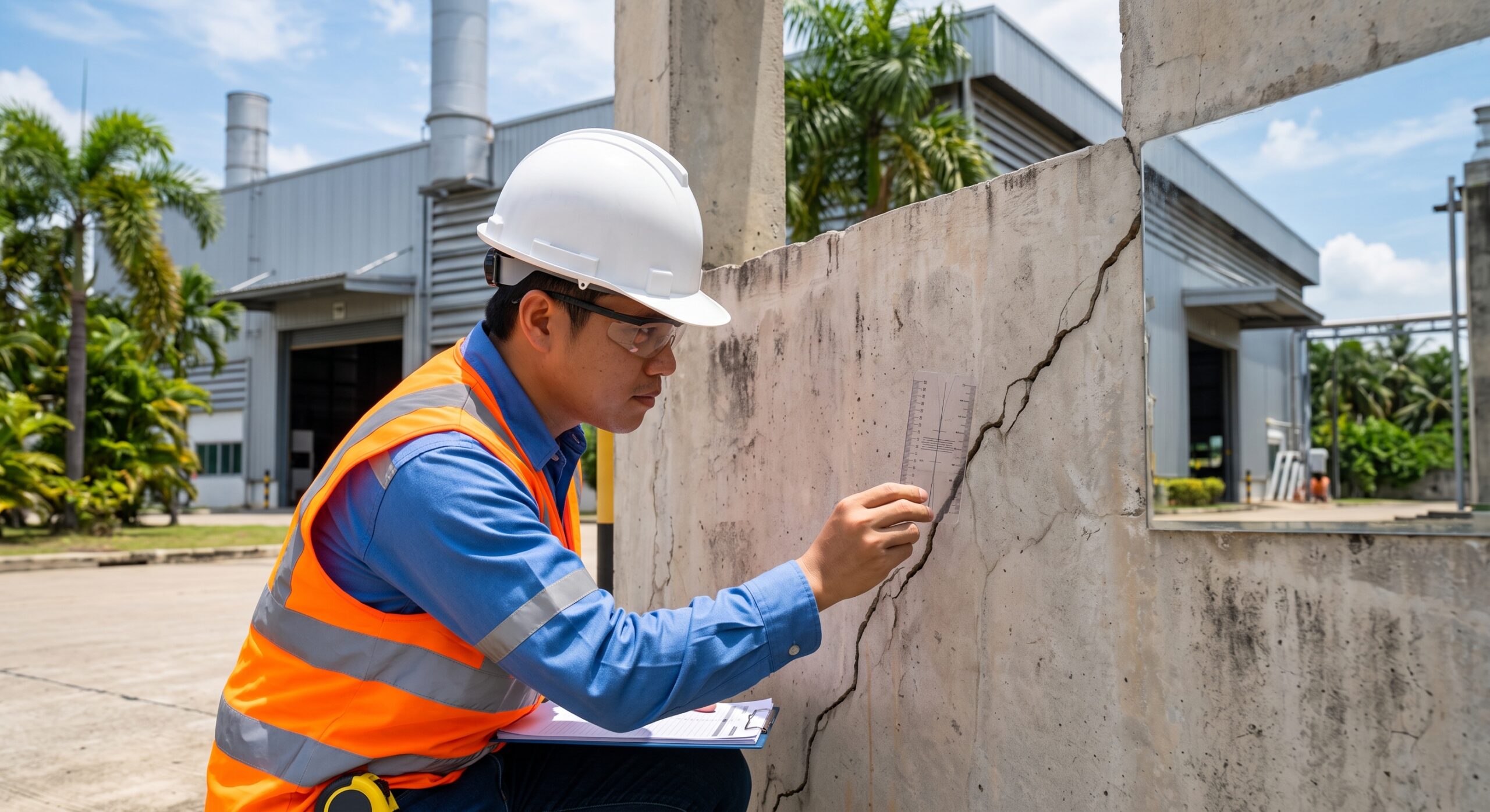
Structural Building Inspection & Assessment: Diagnosing Structural vs. Non-Structural Cracks
Introduction to Structural Diagnostics
Structural building inspection requires meticulous analytical precision. Engineers must distinguish cosmetic flaws from critical structural distress. Cracks serve as early warning signs of mechanical failure. They indicate complex internal stress states within concrete elements. Proper crack diagnosis ensures building safety and structural longevity.
Concrete possesses high compressive strength but low tensile capacity. Tensile stresses easily exceed this capacity, causing inevitable cracking. The American Concrete Institute discusses this in ACI 224R. Complete elimination of cracking is virtually impossible in structures1. Engineers must instead focus on effective crack control procedures.
They must determine if existing cracks threaten structural stability. Active cracks indicate ongoing structural movement or active degradation. Dormant cracks remain stable over long periods of time2. Identifying the root cause is the primary inspection objective. This report provides an exhaustive field guide for engineers. It covers crack geometry, orientation, and advanced diagnostic methodologies.
The Diagnostic Workflow for Field Engineers
Field engineers must follow a systematic and rigorous diagnostic workflow. Hasty conclusions often lead to incorrect repair specifications. Patching a crack prematurely destroys vital diagnostic evidence. The initial observation phase is therefore absolutely critical.
Engineers must record the exact location of the defect. They must note the specific structural element involved. Identifying the elevation and relative position is also vital. This geographical data correlates with localized structural restraints3.
Measurements must utilize highly accurate field instruments. A crack comparator card measures maximum surface width rapidly. A portable crack microscope provides deeper geometric insights. Ultrasonic testing equipment measures internal structural integrity without damage.
Data collection requires strict standardization for subsequent engineering analysis. Photographs must always include a known-scale reference. A ruler or coin provides essential dimensional context. Photographs without scale lack evidentiary value for structural assessment2. Field notebooks must capture environmental conditions and loading states. This comprehensive data set enables accurate root-cause analysis.
Standardized Crack Classification
The width of a crack determines its immediate severity. ACI 224R provides established thresholds for structural evaluation4. Hairline cracks often result from normal plastic shrinkage. Cracks exceeding specific widths require immediate structural assessment.
| Crack Width Range | Severity Classification | Required Engineering Action |
| Below 0.13 mm | Hairline | Monitor annually for dimensional changes. |
| 0.13 mm to 0.30 mm | Fine | Seal surface and monitor quarterly. |
| 0.30 mm to 1.0 mm | Medium | Professional structural assessment within 30 days. |
| 1.0 mm to 2.0 mm | Wide | Prompt structural engineering evaluation required. |
| Above 2.0 mm | Severe | Immediate assessment; restrict structural loading entirely. |
The exposure environment heavily influences tolerable crack widths. Exterior exposure requires tighter crack control than interior environments. Cracks in marine structures demand incredibly strict width limitations. Wide cracks allow moisture and aggressive chlorides to penetrate. This initiates severe corrosion of embedded steel reinforcement5.
Analyzing Crack Geometry and Orientation
Crack orientation reveals the primary stress field direction. Cracks propagate perpendicularly to the principal tensile stresses. Analyzing this geometry allows engineers to reverse-engineer the failure.
Longitudinal Cracks
Longitudinal cracks run parallel to the main structural axis. These defects often indicate severe reinforcement corrosion. As embedded steel rusts, it expands significantly in volume. This expansion generates immense internal radial bursting stresses. The concrete cover eventually spalls and delaminates completely7.
Longitudinal cracks in columns may also indicate compression failure. High axial loads cause lateral expansion due to Poisson’s effect. This lateral strain overcomes the concrete’s tensile capacity.
Transverse Cracks
Transverse cracks run perpendicular to the structural axis. In beams, these indicate high flexural bending moments. They originate at the extreme tension fiber of the element. They propagate upwards toward the structural neutral axis.
Unrestrained shrinkage also produces transverse cracking in large slabs. The concrete attempts to contract but faces subgrade friction. This friction generates uniform tensile stresses across the section.
Diagonal Cracks
Diagonal cracks signify highly dangerous shear stress conditions. They typically form near beam supports and column connections. These specific regions experience the maximum applied shear forces.
Diagonal cracks indicate a brittle failure mechanism. They occur suddenly and lack adequate physical warning signs. They require immediate structural intervention and strengthening6.
Map Cracking
Map cracking features a random, interconnected geometric network. This pattern points to volumetric internal expansion. Alkali-Silica Reaction (ASR) frequently causes severe map cracking9. Drying shrinkage on large surfaces also creates similar patterns. The lack of distinct orientation indicates multidirectional tensile stresses.
Flexural and Shear Failures
Structural loads induce complex stress fields within concrete members. Flexural cracks develop when bending moments exceed cracking capacity. These cracks are generally expected under typical service loads. Modern design philosophies allow for controlled flexural cracking. ACI 318 permits crack formation to utilize steel reinforcement10.
The Gergely-Lutz equation historically predicts flexural crack widths. It relates surface crack width to service steel stress. It also incorporates concrete cover and effective tension area11.
In this formula, represents the maximum expected crack width. The variable denotes the steel stress under service loads. The dimension measures the cover to the bar center. The variable represents the effective concrete tension area. The factor represents the strain gradient ratio11.
Flexural cracks become dangerous when they exceed expected widths. Overloading an element causes yielding of the tensile reinforcement. Yielding drastically increases steel strain and subsequent crack width13. Yielding signifies a severe loss of structural reserve capacity.
Shear failures present a much higher risk than flexural failures. Shear cracks open diagonally across the web of beams. They occur suddenly and without significant prior structural deformation. This highly brittle behavior makes shear cracks extremely critical.
Exterior beam-column joints are especially vulnerable to shear stresses. They face unbalanced lateral loading from wind and earthquakes. Reduced confinement at exterior joints exacerbates this structural vulnerability8.
Structural Settlement and Foundation Movement
Foundation settlement induces massive internal stresses within superstructures. Differential settlement occurs when support points move unequally. This movement forces the building structure to distort. The structure bends and shears to accommodate foundation displacement.
Engineers measure this distortion using the angular distortion parameter. Angular distortion compares differential settlement directly to span length. Skempton and MacDonald established critical threshold limits for buildings. They found that an angular distortion of 1/300 causes cracking. This specific threshold applies to traditional brick and concrete structures14.
Burland and Wroth further refined settlement damage assessment methods. They modeled the entire building as a deep beam. Their unique approach analyzes both bending and shear strains. They concluded that relative rotation accurately predicts structural damage. Hogging and sagging deformation modes create distinctly different cracking patterns17.
| Defect Manifestation | Associated Failure Mechanism | Settlement Indication |
| Diagonal wall cracks | Shear strain from differential movement | Highly likely |
| Vertical foundation cracks | Direct bending of foundation beam | Likely |
| Tapered crack profiles | Rotational building displacement | Definite |
| Parallel floor cracks | Uniform lateral ground strain | Possible |
Settlement cracks exhibit highly distinct physical characteristics. They often feature an offset across the crack face. One side sits visibly higher than the opposing side. This offset confirms active, ongoing shear displacement5.
Settlement cracks frequently taper along their entire length. They are distinctly wider at the top or bottom. Tracking these subtle changes requires precise long-term crack monitoring.
Thermal Expansion and Early-Age Restraint
Temperature changes cause concrete to expand and contract continually. Restraint against this movement generates severe thermal tensile stresses. Early-age thermal cracking occurs shortly after concrete placement.
The hydration of cement generates significant internal heat energy. The concrete core becomes very hot and expands rapidly. The exposed outer surfaces cool rapidly and attempt to contract. This extreme temperature gradient causes internal compression and surface tension. When surface tension exceeds concrete tensile strength, cracking occurs1.
Mass concrete elements are highly susceptible to thermal cracking. Thick rafts, dams, and large columns require strict thermal control. The CIRIA C660 guideline governs early-age thermal crack control. It provides methodologies for predicting expected temperature rises20.
Restraint factors play a critical role in thermal cracking. A new wall cast onto a mature foundation faces restraint. The foundation prevents the new wall from contracting during cooling. This continuous base restraint generates vertical cracks in the wall.
Analytical models calculate these crack widths based on reinforcement. The spacing of reinforcement directly controls the crack spacing. Tighter reinforcement spacing creates smaller, more frequent cracks22.
To mitigate thermal cracking, engineers implement precise cooling strategies. Using chilled water or ice in the mix reduces temperatures. Embedded cooling pipes actively extract heat from mass concrete. Proper curing blankets significantly slow down the surface cooling rate. This minimizes the critical temperature gradient across the section.
Chemical Deterioration Mechanisms
Chemical reactions within concrete destroy structural integrity over time. These reactions generate internal expansion or degrade steel reinforcement. Field engineers must recognize the visual signatures of chemical attacks.
Alkali-Silica Reaction (ASR)
Alkali-Silica Reaction is a devastating internal chemical process. It occurs between reactive silica minerals and cement alkalis. The first stage involves hydroxyl ions attacking siloxane bonds. This dissolves the silica into the internal pore solution.
The dissolved silica reacts with calcium ions from portlandite. This secondary reaction produces a highly hygroscopic silica gel. This gel absorbs internal pore water and swells massively. The swelling generates internal osmotic pressures up to 6 MPa. This pressure easily exceeds the tensile strength of normal concrete23.
ASR visually manifests as extensive and severe map cracking. A gel exudation often appears around the cracked surfaces. ASR requires three components: reactive silica, alkalis, and moisture. Removing moisture limits the ongoing expansion process9.
Definitive ASR diagnosis requires laboratory petrographic examination. ASTM C856 governs the microscopic analysis of hardened concrete cores. Petrographers identify the cracked aggregate and expansive gel plugs. Scanning Electron Microscopy confirms the presence of ASR gel25.
Carbonation and Corrosion
Healthy concrete maintains a highly alkaline chemical environment. The pore solution pH typically rests between 12.5 and 13.5. This high alkalinity creates a passive oxide layer on steel. The passive layer entirely prevents reinforcement corrosion from occurring.
Carbonation effectively destroys this protective chemical environment. Atmospheric carbon dioxide permeates the concrete pore structure. It reacts with calcium hydroxide to form calcium carbonate. This chemical reaction lowers the concrete pH significantly.
When the pH drops below 9.0, passivity is completely lost7. Depassivated steel rusts rapidly in the presence of moisture. Engineers test for carbonation using the phenolphthalein indicator method.
The European Standard EN 14630 governs this diagnostic procedure. Inspectors spray the indicator onto a freshly broken concrete surface27.
| Indicator Color | Concrete Condition | Estimated pH Level |
| Vibrant Pink | Uncarbonated and healthy | Above 9.0 |
| Diffuse Pink | Partially carbonated | 8.0 to 9.0 |
| Colorless | Fully carbonated and degraded | Below 8.0 |
Carbonation depth is compared against the concrete cover depth. If carbonation reaches the steel, active corrosion becomes inevitable. The expansion of rust induces longitudinal cracking and massive spalling.
Non-Destructive Testing (NDT) in the Field
Field engineers rely heavily on Non-Destructive Testing (NDT). NDT provides internal structural data without causing further damage. It allows engineers to map defects across large structural elements.
Ultrasonic Pulse Velocity (UPV) Testing
Ultrasonic Pulse Velocity testing is the premier NDT method. It assesses concrete quality, uniformity, and internal integrity. The method is governed strictly by the ASTM C597 standard28. UPV measures the transit time of ultrasonic compressional waves.
The instrument utilizes two distinct piezoelectric transducers. One transmits a mechanical vibration into the concrete element. The second transducer receives the transmitted ultrasonic wave. Compressional P-waves travel faster than shear or surface waves29.
The velocity is calculated using a simple physical relationship.
Here, is the calculated ultrasonic pulse velocity. is the precise geometric path length. is the measured transit time in microseconds30.
The velocity directly correlates with dynamic elastic modulus and density. High velocities indicate dense, high-quality, defect-free concrete. Internal cracks, voids, and honeycombing disrupt the direct wave path.
The ultrasonic pulse must diffract around these air-filled voids. This structural detour significantly increases the overall transit time. Increased transit time inevitably lowers the calculated pulse velocity31.
Engineers utilize different transducer configurations based on site access. Direct transmission places transducers on opposite parallel faces. This provides the most accurate and reliable velocity measurement. Semi-direct transmission places transducers on adjacent intersecting faces. This configuration effectively evaluates structural corners and concrete joints. Indirect transmission places both transducers on the same face. This specifically evaluates surface quality and estimates crack depths.
| UPV Velocity Range (km/s) | Concrete Quality Grading | Implication for Structure |
| Greater than 4.5 | Excellent | Highly dense, structurally sound |
| 3.5 to 4.5 | Good | Acceptable quality, minor voids |
| 3.0 to 3.5 | Medium | Suspect quality, potential defects |
| Less than 3.0 | Doubtful | Severe degradation or large internal cracks |
The indirect method specifically calculates the depth of surface cracks. Transducers are placed at equal distances from the visible crack. Transit times are compared to readings on solid, uncracked concrete. This mathematical comparison calculates how deep defects penetrate structurally30.
Chain Drag and Hammer Sounding
Delamination occurs when concrete layers separate internally. This usually results from corroding reinforcement expanding near the surface. Sounding methods quickly detect these hidden sub-surface delaminations.
ASTM D4580 standardizes the chain drag and hammer test32. Engineers drag a heavy steel chain across concrete decks. Solid concrete produces a clear, ringing acoustic response. Delaminated areas produce a hollow, dull, or dead sound.
Hammer sounding applies the same acoustic principle to vertical walls. These acoustic tests map the exact boundaries of required repairs34. Sounding is highly effective for detecting moderate to severe delamination.
Advanced Crack Monitoring and Measurement
A single crack inspection provides only a temporal snapshot. Determining structural safety requires analyzing dynamic crack behavior. Engineers must determine if a crack is active or dormant.
Active cracks change their width or length over time. They respond to thermal cycling, changing loads, or ongoing settlement. Dormant cracks remain entirely static regardless of environmental changes. Identifying this status dictates the appropriate repair specification35.
Tell-tale crack monitors provide simple, reliable movement tracking. These devices consist of two overlapping transparent acrylic plates. They feature a high-precision calibrated measurement grid. One plate attaches to each side of the concrete crack36.
As the crack opens or shifts, the plates slide. The crosshair moves across the marked millimeter grid. This provides a direct, visual readout of vertical and horizontal movement. The device achieves a high measurement accuracy of 1.0 mm37. Engineers log these readings systematically over several months.
Automated crack width measurement utilizes advanced digital imagery. High-resolution photographs capture the cracked concrete surface. Computational algorithms convert the images into segmented pixel masks. Orthogonal profiles extract the exact opening width continuously6. This technology removes human error from tedious field measurements.
Structural Strengthening and Repair Strategies
Once diagnosis is complete, engineers prescribe specific repair methodologies. The selected repair must address both the symptom and cause. Ignoring the root cause guarantees that repairs will fail prematurely.
Epoxy and Polyurethane Injection
Crack injection restores structural integrity or prevents water ingress. The choice of injection resin depends entirely on crack dynamics.
Epoxy resins possess extremely high compressive and tensile strengths. They effectively weld the cracked concrete back together. Epoxy is strictly reserved for dormant, non-moving cracks.
If applied to an active crack, the rigid epoxy holds. However, the adjacent concrete will fracture due to ongoing stress35. Polyurethane resins are highly flexible and elastomeric. They expand upon contact with water to form a seal.
Polyurethane accommodates ongoing structural movement without failing. It is the preferred material for sealing active, leaking cracks. Polyurethane stops water intrusion but provides zero structural strengthening38.
Carbon Fiber Reinforced Polymer (CFRP) Strengthening
Many cracks indicate a severe deficit in structural load capacity. The element requires external strengthening to remain safe. Carbon Fiber Reinforced Polymer (CFRP) provides an exceptional solution.
CFRP is lightweight, extremely strong, and highly corrosion-resistant39. ACI 440.2R guides the design of externally bonded FRP systems. CFRP laminates possess tensile strengths vastly exceeding structural steel.
The dry carbon fabric is saturated with structural epoxy resin. It is then bonded directly to the prepared concrete surface. Wet layup systems conform easily to complex structural geometries41.
Flexural strengthening applies CFRP strips to the tension face. This increases the bending capacity of slabs and beams. Shear strengthening applies CFRP fabric to the vertical sides. The fabric acts identically to internal steel shear stirrups39.
The Importance of CFRP Anchorage
CFRP strengthening often fails prematurely due to sudden debonding. The interface between the concrete and epoxy simply peels away. Proper anchorage systems prevent this catastrophic structural delamination.
Transverse CFRP U-wraps provide excellent mechanical anchorage. The U-wrap anchors the ends of longitudinal flexural CFRP plates. This prevents concrete cover separation and plate-end debonding42.
U-wraps do not require drilling into the concrete substrate. Drilling risks damaging internal steel and causes stress concentrations. U-wraps provide superior performance compared to traditional mechanical metallic fasteners.
ACI 440.2R limits the effective strain of the FRP material. This limitation prevents brittle failure modes in the reinforced member. The strengthened structure must still exhibit ductile yielding behavior.
Proper U-wrap anchorage increases the tensile strain capacity achieved. This maximizes the structural efficiency of the expensive CFRP materials43.
Autogenous Self-Healing Concrete
Advanced material science explores autogenous self-healing concrete mechanisms. Concrete possesses a slight, inherent ability to heal fine cracks. Unhydrated cement particles in the crack path react with moisture.
This ongoing hydration creates new calcium silicate hydrate gel. The new gel bridges and seals the microscopic crack entirely44. Self-healing is only effective for extremely narrow crack widths.
ACI 224R limits allowable cracks to promote autogenous self-healing. Crack widths must generally remain below 0.15 mm44. Researchers enhance self-healing using embedded microcapsules or shape memory alloys.
These advanced technologies actively force cracks closed or deploy agents46. Using supplementary cementitious materials like fly ash also improves healing. The pozzolanic reactions continue to bridge gaps over extended periods48.
Regulatory Compliance: Periodic Structural Inspection
Many jurisdictions mandate regular structural inspections for aging buildings. The Singapore Building and Construction Authority (BCA) provides a framework. The Periodic Structural Inspection (PSI) regime ensures urban safety. It targets buildings that have reached 13 years of age.
The BCA enforces PSI under the strict Building Control Act. The regulations mandate rigid timeframes based on building usage. Residential buildings require mandatory structural inspection every 10 years. Non-residential and commercial buildings require inspection every 5 years49.
| Building Classification | Required Inspection Frequency | Age Trigger |
| Commercial / Retail | Every 5 Years | 13th Year |
| Industrial / Factory | Every 5 Years | 13th Year |
| Multi-Storey Residential | Every 10 Years | 13th Year |
| Single-Family Landed | Exempt | N/A |
The Two-Stage PSI Process
The PSI process demands certification by a registered Professional Engineer. The engineer bears personal legal liability for the inspection accuracy49.
Stage 1 consists of a rigorous visual condition assessment. The engineer inspects and maps all accessible structural elements. They document spalling, massive deflections, cracking, and water seepage. Unauthorized structural modifications by tenants are also meticulously recorded.
The engineer submits a formal report to the BCA electronically50. Stage 2 involves detailed investigation and is not always required. It triggers only when Stage 1 identifies severe structural distress.
Stage 2 utilizes NDT methods like UPV, carbonation testing, and coring. The engineer calculates load capacities to verify structural safety. Following Stage 2, remedial repair works must be certified complete50.
Artificial Intelligence now assists with periodic facade and structural inspections. Drones capture high-resolution imagery of inaccessible structural envelopes. AI algorithms detect cracks and spalling with incredible precision. This technology heavily supports the rigid compliance requirements of building codes52.
Works cited
- 224R-01 Control of Cracking in Concrete Structures, https://www.concrete.org/Portals/0/Files/PDF/224R_01Ch3.pdf
- 224.1R-07 Causes, Evaluation, and Repair of Cracks in … – AnyFlip, https://anyflip.com/dqkl/klyd/basic
- Concrete Crack Diagnosis: 5-Step Field Workflow – PCCI, https://pcciglobal.com/insights/concrete-cracking-diagnosis-workflow-dam-owners-engineer/
- 5 Signs Your Building Needs Structural Concrete Repair, https://texasstructuralconcrete.com/resources/signs-building-needs-concrete-repair
- ACI 364.9T-03(11), https://img.antpedia.com/standard/files/pdfs_ora/20230614/ACI/Std/ACI%20364.9T-03%20(2011).pdf
- Automated Crack Width Measurement from Imagery – TarmacView, https://www.tarmacview.com/glossary/crack-width-measurement/
- Concrete Carbonation Testing: A Technical Guide to Asset, https://www.fibrwrap-ccuk.com/blog/concrete-carbonation-testing-a-technical-guide-to-asset-diagnosis-and-life-extension/
- CFRP Strengthening for Beam-Column Joints | PDF – Scribd, https://www.scribd.com/document/911643217/Beam-Column-Junction-Treatment
- PAPER COMMENTARY – EFI Global, https://www.efiglobal.com/alkali-aggregate-reactivity/
- Prediction of Cracking in Reinforced Concrete Structures, https://nvlpubs.nist.gov/nistpubs/Legacy/IR/nistir5634.pdf
- Concrete Crack Width Calculator (Gergely-Lutz) | EngiCalcul, https://engicalcul.com/concrete-design/crack-width-calculator/
- Crack width control Bruurs, MJAM – Pure, https://pure.tue.nl/ws/files/65069424/Crack_width_control_M.J.A.M._Bruurs_Master_Thesis.pdf
- Flexural Crack Widths in Concrete Girders with High-Strength, https://ascelibrary.org/doi/10.1061/%28ASCE%29BE.1943-5592.0000306
- The Allowable Settlements of Building – Skempton and Macdonald, https://www.scribd.com/document/608266533/The-Allowable-Settlements-of-Building-Skempton-and-Macdonald
- University of Southampton Research Repository ePrints Soton, https://eprints.soton.ac.uk/196447/1/smit_thesis.pdf
- 13. AN INTRODUCTION TO FOUNDATION ENGINEERING, http://dadabhoy.edu.pk/shah_moodledata_ehid/filedir/0d/10/0d10080d1a1402497d08e67c6d0b4424f46d515c
- Prediction of Frame Structure Damage Resulting from Deep, https://ascelibrary.org/doi/10.1061/%28ASCE%29GT.1943-5606.0000682
- Deformations and damage to buildings adjacent to deep, https://publications.deltares.nl/1001307_004.pdf
- Concrete Thermal Modelling and Cracking Control, https://bellengineering.com.au/concrete-thermal-modelling-and-cracking-control/
- Temperature Control of Massive High-Strength Concrete Columns, https://www.mdpi.com/2075-5309/15/23/4256
- Early-Age Thermal Crack Control in Concrete: Design Guide C660, https://studylib.net/doc/27794204/ciria-c660-early-age-thermal-crack-control-in-concrete
- (PDF) History of the Development of Analytical Models of Cracking, https://www.researchgate.net/publication/366904812_History_of_the_Development_of_Analytical_Models_of_Cracking_of_Restrained_Walls_on_a_Given_Edge_Since_1968
- Alkali-Silica Reaction (ASR) in Concrete – TarmacView, https://www.tarmacview.com/glossary/alkali-silica-reaction/
- Can Shotcrete be Affected by Alkali Silica Reaction?, https://shotcrete.org/wp-content/uploads/2024/01/Can_Shotcrete_be_Affected_by_ASR_Lukkarila_WebVersion_SCM4Q23.pdf
- Alkali-Silica Reaction – RJ Lee Group, https://www.rjleegroup.com/blog/alkali-silica-reaction
- EUROPEAN STANDARD CEN/TC 104/SC 8 N 883 prEN 14630, https://fereb.be/nl/documenten/technische-info/send/270-the-phenolphthalein-method-env-1504-9/1289-phenolphthalein-test
- SIST EN 14630:2007 – iTeh STANDARD PREVIEW (standards.iteh.ai), https://cdn.standards.iteh.ai/samples/26682/1976e6bb12274ef6a2e8c2b77ec539af/SIST-EN-14630-2007.pdf
- UPV Testing – SiteOps, https://siteops.au/services/upv-testing
- Nondestructive Concrete Testing with Ultrasonic Pulse Velocity (UPV), https://www.rjleegroup.com/blog/nondestructive-evaluation-nde-of-concrete-with-upv
- Ultrasonic Pulse Velocity Test (IS 13311-1) — NABL – NKMPV, https://nkmpv.com/services/ultrasonic-pulse-velocity-test
- Ultrasonic Pulse Velocity (UPV) Test Malaysia – Foundtest, https://foundtest.com/services/concrete-testing/ultrasonic-pulse-velocity-test/
- D4580 – Standard Practice for Measuring Delamination in Concrete, https://standards.globalspec.com/std/14604538/d4580
- Delamination survey | Building surveys and investigations, https://www.birmingham.gov.uk/info/50221/birmingham_city_laboratories/1929/building_surveys_and_investigations/5
- Measuring Delaminations in Concrete Bridge Decks by Sounding1, https://pdfcoffee.com/download/astm-d-4580-03-pdf-free.html
- Concrete Floor Repair: Cracks, Spalling, and Surface Damage, https://floorrepairauthority.com/concrete-floor-repair/
- Geosense Catalogue | PDF | Porosity – Scribd, https://www.scribd.com/document/469418205/Geosense-Catalogue
- Standard Concrete Crack Gauge Clear Crack Monitoring Tool Tell, https://www.daraz.com.bd/products/standard-concrete-crack-gauge-clear-crack-monitoring-tool-tell-tale-crack-measuring-tool-crack-measuring-ruler-i564092253.html
- Concrete Crack Repair: Epoxy vs Polyurethane Injection (ACI 224.1, https://concretepourchecker.com/guides/concrete-crack-repair-epoxy-vs-polyurethane
- Guide for the Design and Construction of Externally Bonded FRP, https://quakewrap.com/frp%20papers/GuideforDesignofExternallyBondedFRP-1.pdf
- 440.2R-17: Guide for the Design and Construction of Externally, https://www.concrete.org/Portals/0/Files/PDF/Previews/440.2R-17_preview.pdf
- The Complete Guide to CFRP Strengthening: Carbon Fiber, https://texasstructuralconcrete.com/resources/complete-guide-cfrp-strengthening
- FRP U-Wrap Anchorage for Preventing Concrete Cover Separation, https://ascelibrary.org/doi/10.1061/%28ASCE%29CC.1943-5614.0001220
- (PDF) Anchorage Effect on Flexural Fiber Reinforced Polymer (FRP, https://www.researchgate.net/publication/323876203_Anchorage_Effect_on_Flexural_Fiber_Reinforced_Polymer_FRP_Laminate_Strengthening_of_Lightweight_Concrete_Beams
- Meta-Analysis and Machine Learning Models to Optimize the … – PMC, https://pmc.ncbi.nlm.nih.gov/articles/PMC8398163/
- Concrete Crack Width Cover | PDF – Scribd, https://www.scribd.com/document/1013211726/Concrete-Crack-Width-cover
- (PDF) Effects of Crack Width and Healing Time on … – ResearchGate, https://www.researchgate.net/publication/360020101_Effects_of_Crack_Width_and_Healing_Time_on_Healing_Performance_of_Microcapsule-Based_Self-Healing_Concrete
- Prestressing and Self-Healing of Fiber-Reinforced and Ultra-High, https://www.mdpi.com/2075-5309/16/7/1289
- Effect of Fly Ash Contents in Autogenous Self-Healing of, https://ascelibrary.org/doi/10.1061/%28ASCE%29MT.1943-5533.0003766
- BCA Periodic Structural Inspection (PSI) Singapore Guide | CVC, https://www.cvcengineers.com/post/bca-periodic-structural-inspection-singapore
- BCA PSI Singapore: Complete Owner’s Guide 2026, https://bca-psi.sg/guide-psi-complete.html
- BCA Periodic Structural Inspection (PSI): A Compliance Guide for, https://structures.com.sg/periodic-structural-inspection-singapore-bca-psi-building-owner-duties/
- Facade Inspection in Singapore – Inspekt AI, https://inspektai.com/singapore/